
Thinking out loud
Where we share the insights, questions, and observations that shape our approach.
Exploring the architecture of automotive electronics: Domain vs. zone
The automotive industry is undergoing a transformative shift towards electrification and automation, with vehicles becoming increasingly reliant on sophisticated electrical and electronic systems. At the heart of this evolution lies the architecture that governs how these systems are organized and integrated within the vehicle. Two prominent paradigms have emerged in this domain: domain architecture and zone architecture.
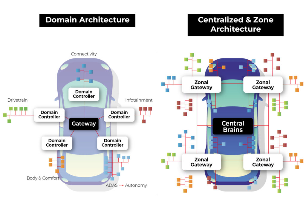
Source: https://www.eetasia.com/the-role-of-centralized-storage-in-the-emerging-zonal-automotive-architecture/
Domain Architecture : In this approach, various electrical and electronic functions are organized around "domains" or functional modules. Each domain is responsible for a specific functional area of the vehicle, such as the engine, braking system, steering system, etc. Each domain may have its independent controllers and communication networks.
Example : In a domain architecture setup, the engine domain would handle all functions related to the vehicle's engine, including ignition, fuel injection, and emissions control. This domain would have its dedicated controller managing these operations.
Zone Architecture : In this approach, the electrical and electronic systems are organized around different "zones" within the vehicle. Zones typically correspond to specific physical areas of the vehicle, such as the front dashboard, passenger cabin, front-end, rear-end, etc. Each zone may have independent electrical and electronic systems tailored to specific needs and functions.
Example : In a zone architecture setup, the front-end zone might encompass functions like lighting, HVAC (Heating, Ventilation, and Air Conditioning), and front-facing sensors for driver assistance systems. These functions would be integrated into a system optimized for the front-end zone's requirements.
Advantages of zonal architecture over domain architecture
In the realm of automotive electronics, zone architecture offers several advantages over domain architecture, revolutionizing the way vehicles are designed, built, and operated. Let's explore these advantages in detail:
1. Software defined vehicle (SDV)
The concept of a Software Defined Vehicle (SDV) represents a paradigm shift in automotive engineering, transforming vehicles into dynamic platforms driven by software innovation. SDV involves decoupling the application layer from the hardware layer, creating a modular and flexible system that offers several significant advantages:
Abstraction of Application from Hardware : In an SDV architecture, applications are abstracted from the underlying hardware, creating a layer of abstraction that simplifies development and testing processes. This separation allows developers to focus on building software functionalities without being constrained by hardware dependencies.
Sensor Agnosticism : One of the key benefits of SDV is the ability to utilize sensors across multiple applications without being tied to specific domains. In traditional domain architectures, sensors are often dedicated to specific functions, limiting their flexibility and efficiency. In an SDV setup, sensors are treated as shared resources that can be accessed and utilized by various applications independently. This sensor agnosticism enhances resource utilization and reduces redundancy, leading to optimized system performance and cost-effectiveness.
Independent Software Updates : SDV enables independent software updates for different vehicle functions and applications. Instead of relying on centralized control units or domain-specific controllers, software functionalities can be updated and upgraded autonomously, enhancing the agility and adaptability of the vehicle.
The OTA system in zonal architecture is also simpler in general as the whole idea is based on abstracting software from hardware, and less tightly coupled software is way easier to update remotely.
With independent software updates, manufacturers can address software bugs, introduce new features and deploy security patches more efficiently. This capability ensures that vehicles remain up-to-date with the latest advancements and safety standards, enhancing user satisfaction and brand reputation.
2. Security
Zone architecture in automotive electronics offers concrete advantages over domain architecture. Let's examine how zone architecture addresses security concerns more effectively compared to domain architecture:
Network Access Vulnerabilities in Domain Architecture:
In domain architecture, connecting to the vehicle network grants access to the entire communication ecosystem, including sensors, actuators, and the central computer.
Particularly concerning is the Controller Area Network (CAN), a widely used protocol lacking built-in authentication and authorization mechanisms. Once connected to a CAN network, an attacker can send arbitrary messages as if originating from legitimate devices.
Granular Access Control in Zone Architecture:
Zone architecture introduces granular access control mechanisms, starting at the nearest gateway to the zone. Each message passing through the gateway is scrutinized, allowing only authorized communications to proceed while rejecting unauthorized ones.
By implementing granular access control, attackers accessing the network gain access only to communication between sensors and the gateway. Moreover, the architecture enables the segregation of end networks based on threat levels.
Network Segmentation for Enhanced Security:
In a zone architecture setup, it's feasible to segment networks based on the criticality of components and potential exposure to threats.
Less critical sensors and actuators can be grouped together on a single CAN network. Conversely, critical sensors vulnerable to external access can be connected via encrypted Ethernet connections, offering an additional layer of security.
In summary, zone architecture provides a reliable solution to security vulnerabilities inherent in domain architecture. By implementing granular access control and network segmentation, zone architecture significantly reduces the attack surface and enhances the overall security posture of automotive systems. This approach ensures that critical vehicle functions remain protected against unauthorized access and manipulation, safeguarding both the vehicle and its occupants from potential cyber threats.
3. Simplified and lightweight wiring
Wiring in automotive electronics plays a critical role in connecting various components and systems within the vehicle. However, it also poses challenges, particularly in terms of weight and complexity. This section, explores how zone architecture addresses these challenges, leading to simplified and lightweight wiring solutions.
The Weight of Wiring: It's important to recognize that wiring is one of the heaviest components in a vehicle, trailing only behind the chassis and engine. In fact, the total weight of wiring harnesses in a vehicle can reach up to 70 kilograms. This significant weight contributes to the overall mass of the vehicle, affecting fuel efficiency, handling, and performance.
Challenges with Traditional Wiring: Traditional wiring systems, especially in domain architecture, often involve long and complex wiring harnesses that span the entire vehicle. This extensive wiring adds to the overall weight and complexity of the vehicle, making assembly and maintenance more challenging.
The Promise of Zone Architecture: Zonal architecture offers a promising alternative by organizing vehicle components into functional zones. This approach allows for more localized placement of sensors, actuators, and control units within each zone, minimizing the distance between components and reducing the need for lengthy wiring harnesses.
Reduced Cable Length: By grouping components together within each zone, zone architecture significantly reduces the overall cable length required to connect these components. Shorter cable runs translate to lower electrical resistance, reduced signal attenuation, and improved signal integrity, resulting in more reliable and responsive vehicle systems.
Optimized Routing and Routing Flexibility: Zone architecture allows for optimized routing of wiring harnesses, minimizing interference and congestion between different systems and components. Moreover, the flexibility inherent in zone architecture enables easier adaptation to different vehicle configurations and customer preferences without the constraints imposed by rigid wiring layouts.
4. Easier and cheaper production
Zonal architecture not only enhances the functionality and efficiency of automotive electronics but also streamlines the production process, making it easier and more cost-effective. Let's explore how zone architecture achieves this:
Modular Assembly : One of the key advantages of zone architecture is its modular nature, which allows for the assembly of individual zones separately before integrating them into the complete vehicle. This modular approach simplifies the assembly process, as each zone can be constructed and tested independently, reducing the complexity of assembly lines and minimizing the risk of errors during assembly.
Reduced Wiring Complexity : The reduction in wiring complexity achieved through zone architecture has a significant impact on production costs. Wiring harnesses are one of the most expensive components in a vehicle, primarily due to the labor-intensive nature of their installation. Each wire must be routed and connected individually, and since each domain typically has its own wiring harness, the process becomes even more laborious.
Automation Challenges with Wiring : Furthermore, automating the wiring process is inherently challenging due to the intricate nature of routing wires and connecting them to various components. While automation has been successfully implemented in many aspects of automotive production, wiring assembly remains largely manual, requiring a significant workforce to complete the task efficiently.
Batch Production of Zones : With zone architecture, the assembly of individual zones can be batch-produced, allowing for standardized processes and economies of scale. This approach enables manufacturers to optimize production lines for specific tasks, reduce setup times between production runs, and achieve greater consistency and quality control.
Integration of Wiring Harnesses : Another advantage of zone architecture is the integration of wiring harnesses into larger assemblies, such as the entire zone. By combining wiring harnesses and assembly for an entire zone into a single process, manufacturers can significantly accelerate production and reduce costs associated with wiring installation and integration.
In summary, zone architecture simplifies and streamlines the production process of vehicles by allowing for modular assembly, reducing wiring complexity, addressing automation challenges, and facilitating batch production of zones. By integrating wiring harnesses into larger assemblies and optimizing production lines, manufacturers can achieve cost savings, improve efficiency, and enhance overall quality in automotive production.
Introduction to zone architecture demonstration
In our Research and Development (R&D) department, we're thrilled to present a demonstration showcasing the power and versatility of zone architecture in automotive electronics. Let's take a closer look at the key components of our setup:
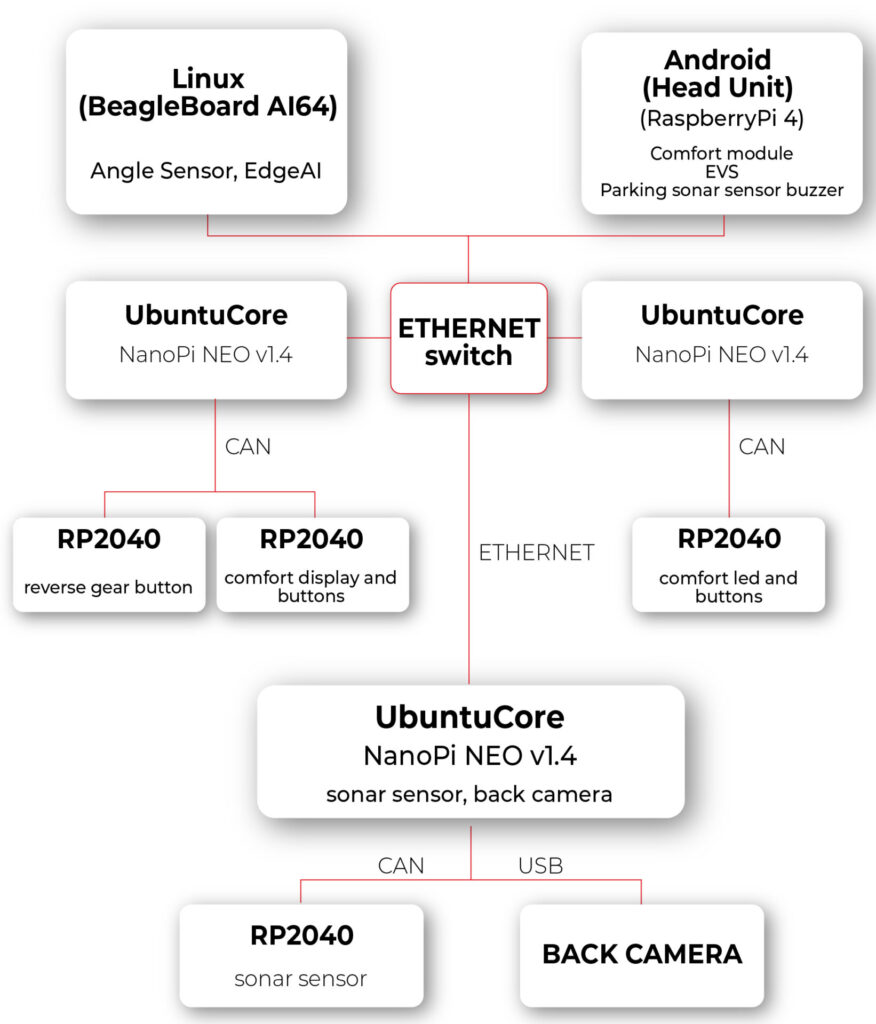
1. Android Computer with Modified VHAL for HVAC:
- Our central computing platform is an Android 14 device running Android Automotive OS (AAOS). This device serves as the hub for system control and communication.
- The modified Vehicle Hardware Abstraction Layer (VHAL) is a pivotal component of our setup. This software layer enables seamless interaction with the vehicle's HVAC module.
- The modified VHAL establishes a connection with the HVAC module through Ethernet and REST API communication protocols, facilitating real-time control and monitoring of HVAC functions.
2. Zone Computer with Ubuntu Core and HVAC Controller Application:
- Each zone in our architecture is equipped with a dedicated computer running Ubuntu Core.
- These zone computers act as the brains of their respective zones, hosting our custom HVAC controller application.
- The HVAC controller application, developed in-house, is responsible for interpreting commands received from the central Android computer and orchestrating HVAC operations within the zone.
- By leveraging Ethernet and REST API communication, as well as the Controller Area Network (CAN) network, the HVAC controller application ensures seamless integration and coordination of HVAC functions.
3. Microcontroller for Physical Interface:
- To provide users with intuitive control over HVAC settings, we've integrated a microcontroller into our setup.
- The microcontroller serves as an interface between the physical controls (buttons and display) and the zone computer.
- Using the CAN interface, the microcontroller relays user inputs to the zone computer, enabling responsive and interactive control of HVAC parameters.
- By bridging the gap between the digital and physical domains, the microcontroller enhances user experience and usability, making HVAC control intuitive and accessible.
The experiment with zone architecture in automotive electronics has proven the effectiveness of our setup. In our solution, pressing a button triggers the transmission of information to the zone computer, where the temperature is adjusted and broadcasted to the respective temperature displays in the zone and to the main Android Automotive OS (head unit IVI). Additionally, changing the temperature via the interface on Android results in sending information to the appropriate zone, thereby adjusting the temperature in that zone.
During the hardware layer testing, we utilized the REST API protocol to expedite implementation. However, we observed certain limitations of this solution. Specifically, we anticipated from the outset that the REST API protocol would not suffice for our needs. The VHAL in the Android system needs to know the HTTP addresses of individual zones and specify to which zone the temperature change should be sent. This approach is not very flexible and may introduce delays associated with each connection to the HTTP server.
In the next article, we plan to review available communication protocols and methods of message description in such a network. Our goal will be to find protocols that excel in terms of speed, flexibility of application, and security. By doing so, we aim to further refine our solution and maximize its effectiveness in the context of zone architecture in automotive electronics.

Addressing data governance challenges in enterprises through the use of LLM Hubs
In an era where more than 80% of enterprises are expected to use Generative AI by 2026, up from less than 5% in 2023, the integration of AI chatbots is becoming increasingly common. This adoption is driven by the significant efficiency boosts these technologies offer, with over half of businesses now deploying conversational AI for customer interactions.
In fact, 92% of Fortune 500 companies are using OpenAI’s technology, with 94% of business executives believing that AI is a key to success in the future.
Challenges to GenAI implementation
The implementation of large language models (LLMs) and AI-driven chatbots is a challenging task in the current enterprise technology scene. Apart from the complexity of integrating these technologies, there is a crucial need to manage the vast amount of data they process securely and ethically. This emphasizes the importance of having robust data governance practices in place.
Organizations deploying generative AI chatbots may face security risks associated with both external breaches and internal data access. Since these chatbots are designed to streamline operations, they require access to sensitive information . Without proper control measures in place, there is a high possibility that confidential information may be inadvertently accessed by unauthorized personnel.
For example, chatbots or AI tools are used to automate financial processes or provide financial insights. Failures in secure data management in this context may lead to malicious breaches.
Similarly, a customer service bot may expose confidential customer data to departments that do not have a legitimate need for it. This highlights the need for strict access controls and proper data handling protocols to ensure the security of sensitive information.
Dealing with complexities of data governance and LLMs
To integrate LLMs into current data governance frameworks, organizations need to adjust their strategy. This lets them use LLMs effectively while still following important standards like data quality, security, and compliance.
- It is crucial to adhere to ethical and regulatory standards when using data within LLMs. Establish clear guidelines for data handling and privacy.
- Devise strategies for the effective management and anonymization of the vast data volumes required by LLMs.
- Regular updates to governance policies are necessary to keep pace with technological advancements, ensuring ongoing relevance and effectiveness.
- Implement strict oversight and access controls to prevent unauthorized exposure of sensitive information through, for example, chatbots.
Introducing the LLM hub: centralizing data governance
An LLM hub empowers companies to manage data governance effectively by centralizing control over how data is accessed, processed, and used by LLMs within the enterprise. Instead of implementing fragmented solutions, this hub serves as a unified platform for overseeing and integrating AI processes.
By directing all LLM interactions through this centralized platform, businesses can monitor how sensitive data is being handled. This guarantees that confidential information is only processed when required and in full compliance with privacy regulations.

Role-Based Access Control in the LLM hub
A key feature of the LLM Hub is its implementation of Role-Based Access Control (RBAC) . This system enables precise delineation of access rights, ensuring that only authorized personnel can interact with specific data or AI functionalities. RBAC limits access to authorized users based on their roles in their organization. This method is commonly used in various IT systems and services, including those that provide access to LLMs through platforms or hubs designed for managing these models and their usage.
In a typical RBAC system for an LLM Hub, roles are defined based on the job functions within the organization and the access to resources that those roles require. Each role is assigned specific permissions to perform certain tasks, such as generating text, accessing billing information, managing API keys, or configuring model parameters. Users are then assigned roles that match their responsibilities and needs.
Here are some of the key features and benefits of implementing RBAC in an LLM Hub:
- By limiting access to resources based on roles, RBAC helps to minimize potential security risks. Users have access only to the information and functionality necessary for their roles, reducing the chance of accidental or malicious breaches.
- RBAC allows for easier management of user permissions. Instead of assigning permissions to each user individually, administrators can assign roles to users, streamlining the process and reducing administrative overhead.
- For organizations that are subject to regulations regarding data access and privacy, RBAC can help ensure compliance by strictly controlling who has access to sensitive information.
- Roles can be customized and adjusted as organizational needs change. New roles can be created, and permissions can be updated as necessary, allowing the access control system to evolve with the organization.
- RBAC systems often include auditing capabilities, making it easier to track who accessed what resources and when. This is crucial for investigating security incidents and for compliance purposes.
- RBAC can enforce the principle of separation of duties, which is a key security practice. This means that no single user should have enough permissions to perform a series of actions that could lead to a security breach. By dividing responsibilities among different roles, RBAC helps prevent conflicts of interest and reduces the risk of fraud or error.
Practical application: safeguarding HR Data
Let's break down a practical scenario where an LLM Hub can make a significant difference - managing HR inquiries:
- Scenario : An organization employed chatbots to handle HR-related questions from employees. These bots need access to personal employee data but must do so in a way that prevents misuse or unauthorized exposure.
- Challenge: The main concern was the risk of sensitive HR data—such as personal employee details, salaries, and performance reviews—being accessed by unauthorized personnel through the AI chatbots. This posed a significant risk to privacy and compliance with data protection regulations.
- Solution with the LLM hub :
- Controlled access: Through RBAC, only HR personnel can query the chatbot for sensitive information, significantly reducing the risk of data exposure to unauthorized staff.
- Audit trails: The system maintained detailed audit trails of all data access and user interactions with the HR chatbots, facilitating real-time monitoring and swift action on any irregularities.
- Compliance with data privacy laws: To ensure compliance with data protection regulations, the LLM Hub now includes automated compliance checks. These help to adjust protocols as needed to meet legal standards.
- Outcome: The integration of the LLM Hub at the company led to a significant improvement in the security and privacy of HR records. By strictly controlling access and ensuring compliance, the company not only safeguarded employee information but also strengthened its stance on data ethics and regulatory adherence.
Conclusion
Robust data governance is crucial as businesses embrace LLMs and AI. The LLM Hub provides a forward-thinking solution for managing the complexities of these technologies. Centralizing data governance is key to ensuring that organizations can leverage AI to improve their operational efficiency without compromising on security, privacy, or ethical standards. This approach not only helps organizations avoid potential pitfalls but also enables sustainable innovation in the AI-driven enterprise landscape.


Fleet management task with AWS IoT – overcoming limitations of Docker Virtual Networks
We’re working for a client that produces fire trucks. There is a list of requirements and the architecture proposal in the first article and a step-by-step implementation of the prototype in the second one . This time, we’re going to close the topic with DHCP implementation and UDP tests.
DHCP server and client
A major issue with Docker is the need to assign IP addresses for containers. It is impractical to rely on automatic address assignments managed by Docker or to manually set addresses when containers are started. The architecture intended for IoT edge should ensure that the state of the device can be easily reproduced even after a power failure or reboot.
It may also be necessary to set fixed addresses for containers that will be the reference point for the entire architecture - see the Router container in our previous text. It is also worth considering the scenario where an external provider wants to connect to the edge device with extra devices. As part of the collaboration, it may be necessary to provide immutable IP addresses, e.g., for IP discovery service.
Our job is to provide a service to assign IP addresses from configurable pools for both physical and virtual devices in VLANs. It sounds like DHCP and indeed, it is DHCP, but it’s not so simple with Docker. Unfortunately, Docker uses its own addressing mechanism that cannot be linked to the network DHCP server.
The proposed solution will rely on a DHCP server and a DHCP client. At startup, the script responsible for running the Docker image will call the DHCP client and receive information about the MAC address and IP address the container will have.
Ultimately, we want to get a permanent configuration that is stored as a file or some simple database for the above. This will give us an immutable configuration for the basic parameters of the Docker container. To connect the MAC address, IP address, and Docker container, we propose adding the name of the potential Docker container to the record. This will create a link for the 3 elements that uniquely identifies the Docker container.
When the script starts, it queries the DHCP server for a possible available IP address and checks beforehand if there is already a lease for the IP/MAC address determined from the Docker container name.
This achieves a configuration that is resistant to IP conflicts and guarantees the reusability of previously assigned IP addresses.
DHCP server
For our use-case, we’ve decided to rely on isc-dhcp-server package. This is a sample configuration you can adjust for your needs.
dhcpd.conf
authoritative;
one-lease-per-client true;

subnet 10.0.1.0 netmask 255.255.255.0 {
  range 10.0.1.2 10.0.1.200;
  option domain-name-servers 8.8.8.8, 8.8.4.4;
  option routers 10.0.1.3;
  option subnet-mask 255.255.255.0;
  default-lease-time 3600;
  max-lease-time 7200;
}
subnet 10.0.2.0 netmask 255.255.255.0 {
  range 10.0.2.2 10.0.1.200;
  option domain-name-servers 8.8.8.8, 8.8.4.4;
  option routers 10.0.2.3;
  option subnet-mask 255.255.255.0;
  default-lease-time 3600;
  max-lease-time 7200;
}
Here is the breakdown for each line in the mentioned configuration. There are two subnets configured with two address pools for each VLAN in our network.
authoritative - this directive means that the DHCP server is the authoritative source for the network. If a client queries with an IP address that it was given by another DHCP server, this server will tell the client that the IP address is invalid, effectively forcing the client to ask for a new IP address.
one-lease-per-client - this ensures that each client gets only one lease at a time. This helps avoid scenarios where a single client might end up consuming multiple IP addresses, leading to a reduced available IP pool.
option domain-name-servers – this assigns DNS servers to the DHCP clients. In this case, it's using Google's public DNS servers (8.8.8.8 and 8.8.4.4).
option routers – this assigns a default gateway for the DHCP clients. Devices in this network will use 10.0.1.3 as their way out of the local network, likely to reach the internet or other networks.
option subnet-mask – this specifies the subnet mask to be assigned to DHCP clients, which in this case is 255.255.255.0. It determines the network portion of an IP address.
default-lease-time – specifies how long, in seconds, a DHCP lease will be valid if the client doesn't ask for a specific lease time. Here, it's set to 3600 seconds, which is equivalent to 1 hour.
max-lease-time - this sets the maximum amount of time, in seconds, a client can lease an IP address. Here, it's 7200 seconds or 2 hours.
DHCP Client
In our scenario, all new application containers are added to the system via bash commands executed on the Host – the firetruck’s main computer or Raspberry PI in our prototype. See the previous chapter for adding containers commands reference. The command requires IP addresses and gateways for each container.
Our approach is to obtain an address from the DHCP server (as dynamic IP) and set up a container with the address configured as static IP. To achieve this, we need a shell-friendly DHCP client. We’ve decided to go with a Python script that can be called when creating new containers.
DHCP Client Example (Python)
See comments in the scripts below for explanations of each block.
from scapy.layers.dhcp import BOOTP, DHCP
from scapy.layers.inet import UDP, IP, ICMP
from scapy.layers.l2 import Ether
from scapy.sendrecv import sendp, sniff

# Sendind discovery packet for DHCP
def locate_dhcp(src_mac_addr):
    packet = Ether(dst='ff:ff:ff:ff:ff:ff', src=src_mac_addr, type=0x0800) / IP(src='0.0.0.0', dst='255.255.255.255') / \
          UDP(dport=67, sport=68) / BOOTP(op=1, chaddr=src_mac_addr) / DHCP(options=[('message-type', 'discover'), 'end'])
    sendp(packet, iface="enp2s0")

# Receiving offer by filtering out packets packet[DHCP].options[0][1] == 2
def capture_offer():
    return sniff(iface="enp2s0", filter="port 68 and port 67",
                 stop_filter=lambda packet: BOOTP in packet and packet[BOOTP].op == 2 and packet[DHCP].options[0][1] == 2,
                 timeout=5)

# Transmitting packets with accepted offer (IP) from DHCP
def transmit_request(src_mac_addr, req_ip, srv_ip):
    packet = Ether(dst='ff:ff:ff:ff:ff:ff', src=src_mac_addr, type=0x0800) / IP(src='0.0.0.0', dst='255.255.255.255') / \
          UDP(dport=67, sport=68) / BOOTP(op=1, chaddr=src_mac_addr) / \
          DHCP(options=[('message-type', 'request'), ("client_id", src_mac_addr), ("requested_addr", req_ip),
                        ("server_id", srv_ip), 'end'])
    sendp(packet, iface="enp2s0")

# Reading acknowledgement from DHCP. Filtering out packet[BOOTP].op == 2 and packet[DHCP].options[0][1] == 5 and ports 68/67
def capture_acknowledgement():
    return sniff(iface="enp2s0", filter="port 68 and port 67",
                 stop_filter=lambda packet: BOOTP in packet and packet[BOOTP].op == 2 and packet[DHCP].options[0][1] == 5,
                 timeout=5)

# Ping offered IP address
def transmit_test_packet(src_mac_addr, src_ip_addr, dst_mac_addr, dst_ip_addr):
    packet = Ether(src=src_mac_addr, dst=dst_mac_addr) / IP(src=src_ip_addr, dst=dst_ip_addr) / ICMP()
    sendp(packet, iface="enp2s0")


if __name__ == "__main__":
    # dummy mac address
    mac_addr = "aa:bb:cc:11:22:33"
    print("START")
    print("SEND: Discover")
    locate_dhcp(mac_addr)
    print("RECEIVE: Offer")
    received_packets = capture_offer()
    server_mac_addr = received_packets[0]["Ether"].src
    bootp_response = received_packets[0]["BOOTP"]
    server_ip_addr = bootp_response.siaddr
    offered_ip_addr = bootp_response.yiaddr
    print("OFFER:", offered_ip_addr)
    print("SEND: Request for", offered_ip_addr)
    transmit_request(mac_addr, offered_ip_addr, server_ip_addr)
    print("RECEIVE: Acknowledge")
    received_packets2 = capture_acknowledgement()
    print("ACKNOWLEDGE:", offered_ip_addr)
    print("SEND: Test IP Packet")
    transmit_test_packet(mac_addr, offered_ip_addr, server_mac_addr, server_ip_addr)
    print("END")
Let’s talk about our use case.
The business requirement is to add another device to the edge - perhaps a thermal imaging camera. Our assumption is to guarantee as fully automatic onboarding of the device in our system as possible. Adding a new device will also mean, in our case, connecting it to the customer-provided Docker container.
Our expected result is to get a process that registers the new Docker container with the assigned IP address from the DHCP server. The IP address is, of course, dependent on the VLAN in which the new device will be located.
In summary, it is easy to see that plugging in a new device at this point just means that the IP address is automatically assigned and bound. The new device is aware of where the Router container is located - so communication is guaranteed from the very beginning.
UDP broadcast and multicast setup
Broadcast UDP is a method for sending a message to all devices on a network segment, which allows for efficient communication and discovery of other devices on the same network. In an IoT context, this can be used for the discovery of devices and services, such as finding nearby devices for data exchange or sending a command to all devices in a network.
Multicast, on the other hand, allows for the efficient distribution of data to a group of devices on a network. This can be useful in scenarios where the same data needs to be sent to multiple devices at the same time, such as a live video stream or a software update.
One purpose of the architecture was to provide a seamless, isolated, LAN-like environment for each application. Therefore, it was critical to enable applications to use not only direct, IP, or DNS-based communication but also to allow multicasting and broadcasting messages. These protocols enable devices to communicate with each other in a way that is scalable and bandwidth-efficient, which is crucial for IoT systems where there may be limited network resources available.
The presented architecture provides a solution for dockerized applications that use UDP broadcast/multicast. The router Docker container environment is intended to host applications that are to distribute data to other containers in the manner.
Let’s check whether those techniques are available to our edge networks.
Broadcast
The test phase should start on the Container1 container with an enabled UDP listener. For that, run the command.
nc -ulp 5000
The command uses the netcat (nc) utility to listen (-l) for incoming UDP (-u) datagrams on port 5000 (-p 5000).
Then, let’s produce a message on the Router container.
echo -n "foo" | nc -uv -b -s 10.0.1.3 -w1 10.0.1.255 5000
The command above is an instruction that uses the echo and netcat to send a UDP datagram containing the string "foo" to all devices on the local network segment.
Breaking down the command:
echo -n "foo" - This command prints the string "foo" to standard output without a trailing newline character.
nc - The nc command is used to create network connections and can be used for many purposes, including sending and receiving data over a network.
-uv - These options specify that nc should use UDP as the transport protocol and that it should be run in verbose mode.
-b - This option sets the SO_BROADCAST socket option, allowing the UDP packet to be sent to all devices on the local network segment.
-s 10.0.1.3 - This option sets the source IP address of the UDP packet to 10.0.1.3.
-w1 - This option sets the timeout for the nc command to 1 second.
10.0.1.255 - This is the destination IP address of the UDP packet, which is the broadcast address for the local network segment.
5000 - This is the destination port number for the UDP packet.
Please note that both source and destination addresses belong to VLAN 1. Therefore, the datagram is sent via the eth0 interface to this VLAN only.
The expected result is the docker container Container1 receiving the message from the Router container via UDP broadcast.
Multicast
Let's focus on Docker Container parameters specified when creating containers (Docker containers [execute on host] sub-chapter in the previous article ). In the context of Docker containers, the --sysctl net.ipv4.icmp_echo_ignore_broadcasts=0 option is crucial if you need to enable ICMP echo requests to the broadcast address inside the container. For example, if your containerized application relies on UDP broadcast for service discovery or communication with other containers, you may need to set this parameter to 0 to allow ICMP echo requests to be sent and received on the network.
Without setting this parameter to 0, your containerized application may not be able to communicate properly with other containers on the network or may experience unexpected behavior due to ICMP echo requests being ignored. Therefore, the --sysctl net.ipv4.icmp_echo_ignore_broadcasts=0 option can be crucial in certain Docker use cases where ICMP echo requests to the broadcast address are needed.
Usage example
Run the command below in the container Container1 (see previous chapter for naming references). We use socat, which is a command line utility that establishes a bidirectional byte stream and transfers data between them. Please note that the IP address of the multicast group does not belong to the VLAN 1 address space.
socat -u UDP4-RECV:22001,ip-add-membership=233.54.12.234:eth0 /dev/null &
Then, add the route to the multicast group.
ip route add 233.54.12.234/32 dev eth0
You can ping the address from Device 1 to verify the group has been created.
ping -I eth0 -t 2 233.54.12.234
As you can see, an interface parameter is required with the ping command to enforce using the correct outgoing interface. You can also limit the TTL parameter (-t 2) to verify the route length to the multicast group.
Now, use socat on Device1 to open the connection inside the group.
ip route add 233.54.12.234/32 dev eth0
socat STDIO UDP-DATAGRAM:233.54.12.234:22001
Please note you have to setup the route to avoid sending packets to “unknown network” directly to the router.
Now, you can type the message on Device1 and use tcpdump on Container1 to see the incoming message.
tcpdump -i eth0 -Xavvv

Summary
Nowadays, a major challenge faced by developers and customers is to guarantee maximum security while ensuring compatibility and openness to change for edge devices. As part of IoT, it is imperative to keep in mind that the delivered solution may be extended in the future with additional hardware modules, and thus, the environment into which this module will be deployed must be ready for changes.
This problem asks the non-trivial question of how to meet business requirements while taking into account all the guidelines from standards from hardware vendors or the usual legal standards.
Translating the presented architecture into a fire trucks context, all the requirements from the introduction regarding isolation and modularity of the environment have been met. Each truck has the ability to expand the connected hardware while maintaining security protocols. In addition, the Docker images that work with the hardware know only their private scope and the router's scope.
The proposed solution provides a ready answer on how to obtain a change-ready environment that meets security requirements. A key element of the architecture is to guarantee communication for applications only in the VLAN space in which they are located.
This way, any modification should not affect already existing processes on the edge side. It is also worth detailing the role played by the Router component. With it, we guarantee a way to communicate between Docker containers while maintaining a configuration that allows you to control network traffic.
We have also included a solution for UDP Broadcast / Multicast communication. Current standards among hardware include solutions that transmit data via the standard. This means that if, for example, we are waiting for emergency data on a device, we must also be ready to handle Broadcasts and ensure that packets are consumed only by those components that are designed for this purpose.
Summarizing the presented solution, one should not forget about applications in other industries as well. The idea of independent Docker images and modularity for hardware allows application even in the Automotive and high-reliability areas, where the use of multiple devices, not necessarily from the same supplier, is required.
We encourage you to think about further potential applications and thank you for taking the time to read.


Exploring Texas Instruments Edge AI: Hardware acceleration for efficient computation
In recent years, the field of artificial intelligence (AI) has witnessed a transformative shift towards edge computing, enabling intelligent decision-making to occur directly on devices rather than relying solely on cloud-based solutions. Texas Instruments, a key player in the semiconductor industry, has been at the forefront of developing cutting-edge solutions for Edge AI. One of the standout features of their offerings is the incorporation of hardware acceleration for efficient computation, which significantly improves the performance of AI models on resource-constrained devices.
Pros and cons of running AI models on embedded devices vs. cloud
In the evolving landscape of artificial intelligence , the decision to deploy models on embedded devices or rely on cloud-based solutions is a critical consideration. This chapter explores the advantages and disadvantages of running AI models on embedded devices, emphasizing the implications for efficiency, privacy, latency, and overall system performance.
Advantages of embedded AI
- Low Latency
One of the primary advantages of embedded AI is low latency. Models run directly on the device, eliminating the need for data transfer to and from the cloud. This results in faster response times, making embedded AI ideal for applications where real-time decision-making is crucial. - Privacy and Security
Embedded AI enhances privacy by processing data locally on the device. This mitigates concerns related to transmitting sensitive information to external servers. Security risks associated with data in transit are significantly reduced, contributing to a more secure AI deployment. - Edge Computing Efficiency
Utilizing embedded AI aligns with the principles of edge computing. By processing data at the edge of the network, unnecessary bandwidth usage is minimized, and only relevant information is transmitted to the cloud. This efficiency is especially beneficial in scenarios with limited network connectivity. What’s more, some problems are very inefficient to solve on cloud-based AI models, for example: video processing with real time output. - Offline Functionality
Embedded AI allows for offline functionality, enabling devices to operate independently of internet connectivity. This feature is advantageous in remote locations or environments with intermittent network access, as it expands the range of applications for embedded AI. - Reduced Dependence on Network Infrastructure
Deploying AI models on embedded devices reduces dependence on robust network infrastructure. This is particularly valuable in scenarios where maintaining a stable and high-bandwidth connection is challenging or cost ineffective. AI feature implemented on the cloud platform will be unavailable in the car after the connection is lost.
Disadvantages of embedded AI
- Lack of Scalability
Scaling embedded AI solutions across a large number of devices can be challenging. Managing updates, maintaining consistency, and ensuring uniform performance becomes more complex as the number of embedded devices increases. - Maintenance Challenges
Updating and maintaining AI models on embedded devices can be more cumbersome compared to cloud-based solutions. Remote updates may be limited, requiring physical intervention for maintenance, which can be impractical in certain scenarios. - Initial Deployment Cost
The initial cost of deploying embedded AI solutions, including hardware and development, can be higher compared to cloud-based alternatives. However, this cost may be offset by long-term benefits, depending on the specific use case and scale. - Limited Computational Power
Embedded devices often have limited computational power compared to cloud servers. This constraint may restrict the complexity and size of AI models that can be deployed on these devices, impacting the range of applications they can support. - Resource Constraints
Embedded devices typically have limited memory and storage capacities. Large AI models may struggle to fit within these constraints, requiring optimization or compromising model size for efficient deployment.
The decision to deploy AI models on embedded devices or in the cloud involves careful consideration of trade-offs. While embedded AI offers advantages in terms of low latency, privacy, and edge computing efficiency, it comes with challenges related to scalability, maintenance, and limited resources.
However, chipset manufacturers are constantly engaged in refining and enhancing their products by incorporating specialized modules dedicated to hardware-accelerated model execution. This ongoing commitment to innovation aims to significantly improve the overall performance of devices, ensuring that they can efficiently run AI models. The integration of these hardware-specific modules not only promises comparable performance but, in certain applications, even superior efficiency.
Deploy AI model on embedded device workflow
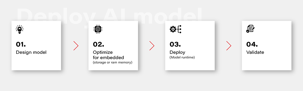
1. Design Model
Designing an AI model is the foundational step in the workflow. This involves choosing the appropriate model architecture based on the task at hand, whether it's classification, regression, or other specific objectives. This is out of the topic for this article.
2. Optimize for Embedded (Storage or RAM Memory)
Once the model is designed, the next step is to optimize it for deployment on embedded devices with limited resources. This optimization may involve reducing the model size, minimizing the number of parameters, or employing quantization techniques to decrease the precision of weights. The goal is to strike a balance between model size and performance to ensure efficient operation within the constraints of embedded storage and RAM memory.
3. Deploy (Model Runtime)
Deploying the optimized model involves integrating it into the embedded system's runtime environment. While there are general-purpose runtime frameworks like TensorFlow Lite and ONNX Runtime, achieving the best performance often requires leveraging dedicated frameworks that utilize hardware modules for accelerated computations. These specialized frameworks harness hardware accelerators to enhance the speed and efficiency of the model on embedded devices.
4. Validate
Validation is a critical stage in the workflow to ensure that the deployed model performs effectively on the embedded device. This involves rigorous testing using representative datasets and scenarios. Metrics such as accuracy, latency, and resource usage should be thoroughly evaluated to verify that the model meets the performance requirements. Validation helps identify any potential issues or discrepancies between the model's behavior in the development environment and its real-world performance on the embedded device.
Deploy model on Ti Edge AI and Jacinto 7
Deploying an AI model on Ti Edge AI and Jacinto 7 involves a series of steps to make the model work efficiently with both regular and specialized hardware. In simpler terms, we'll walk through how the model file travels from a general Linux environment to a dedicated DSP core, making use of special hardware features along the way.
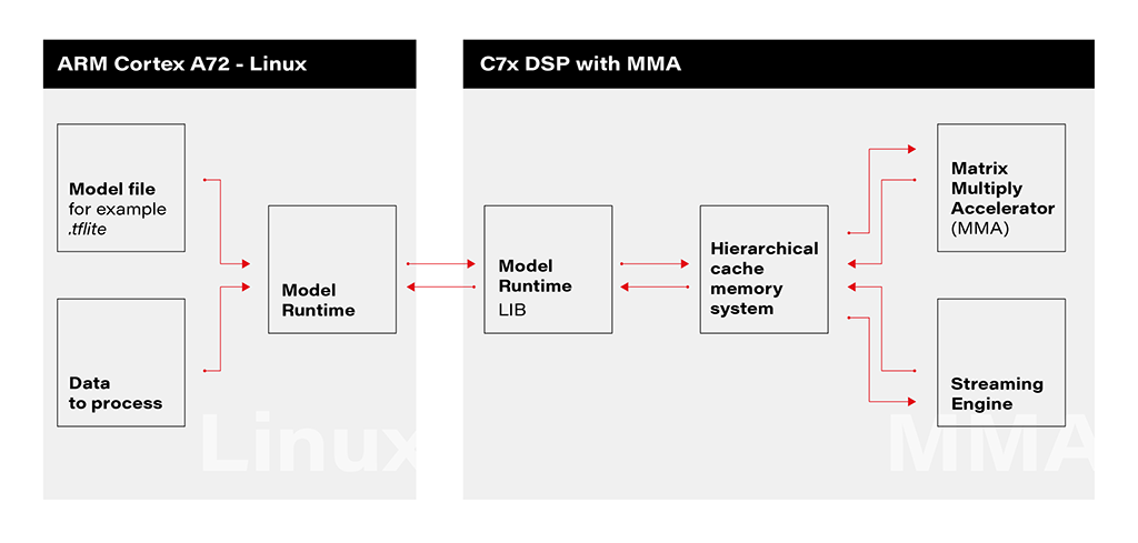
1. Linux Environment on A72 Core: The deployment process initiates within the Linux environment running on the A72 core. Here, a model file resides, ready to be utilized by the application's runtime. The model file, often in a standardized format like .tflite, serves as the blueprint for the AI model's architecture and parameters.
2. Runtime Application on A72 Core: The runtime application, responsible for orchestrating the deployment, receives the model file from the Linux environment. This runtime acts as a proxy between the user, the model, and the specialized hardware accelerator. It interfaces with the Linux environment, handling the transfer of input data to be processed by the model.
3. Connection to C7xDSP Core: The runtime application establishes a connection with its library executing on the C7xDSP core. This library, finely tuned for hardware acceleration, is designed to efficiently process AI models using specialized modules such as the Matrix Multiply Accelerator.
4. Loading Model and Data into Memory: The library on the C7x DSP core receives the model description and input data, loading them into memory for rapid access. This optimized memory utilization is crucial for achieving efficient inference on the dedicated hardware.
5. Computation with Matrix Multiply Accelerator: Leveraging the power of the Matrix Multiply Accelerator, the library performs the computations necessary for model inference. The accelerator efficiently handles matrix multiplications, a fundamental operation in many neural network models.
The matrix multiply accelerator (MMA) provides the following key features:
- Support for a fully connected layer using matrix multiply with arbitrary dimension
- Support for convolution layer using 2D convolution with matrix multiply with read panel Support for ReLU non-linearity layer OTF
- Support for high utilization (>85%) for a typical convolutional neural network (CNN), such as AlexNet, ResNet, and others
- Ability to support any CNN network topologies limited only by memory size and bandwidth
6. Result Return to User via Runtime on Linux: Upon completion of computations, the results are returned to the user through the runtime application on the Linux environment. The inference output, processed with hardware acceleration, provides high-speed, low-latency responses for real-time applications.
Object recognition with AI model on Jacinto 7: Real-world challenges
In this chapter, we explore a practical example of deploying an AI model on Jacinto 7 for object recognition. The model is executed according to the provided architecture, utilizing the TVM-CL-3410-gluoncv-mxnet-mobv2 model from the Texas Instruments Edge AI Model Zoo. The test images capture various scenarios, showcasing both successful and challenging object recognition outcomes.
The deployment architecture aligns with the schematic provided, incorporating Jacinto 7's capabilities to efficiently execute the AI model. The TVM-CL-3410-gluoncv-mxnet-mobv2 model is utilized, emphasizing its pre-trained nature for object recognition tasks.
Test Scenarios: A series of test images were captured to evaluate the model's performance in real-world conditions. Notably:
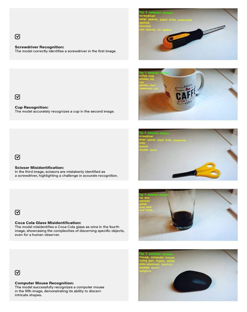
Challenges and Real-world Nuances: The test results underscore the challenges of accurate object recognition in less-than-ideal conditions. Factors such as image quality, lighting, and ambiguous object appearances contribute to the intricacy of the task. The third and fourth images, where scissors are misidentified as a screwdriver, and a Coca-Cola glass is misrecognized as wine, exemplify situations where even a human might face difficulty due to limited visual information-
Quality Considerations: The achieved results are noteworthy, considering the less-than-optimal quality of the test images. The chosen camera quality and lighting conditions intentionally mimic challenging real-world scenarios, making the model's performance commendable.
Conclusion: The real-world example of object recognition on Jacinto 7 highlights the capabilities and challenges associated with deploying AI models in practical scenarios. The successful identification of objects like a screwdriver, cup, and computer mouse demonstrates the model's efficacy. However, misidentifications in challenging scenarios emphasize the need for continuous refinement and adaptation, acknowledging the intricacies inherent in object recognition tasks, especially in dynamic and less-controlled environments.
How to develop AI-driven personal assistants tailored to automotive needs. Part 3
Blend AI assistant concepts together
This series of articles starts with a general chatbot description – what it is, how to deploy the model, and how to call it. The second part is about tailoring – how to teach the bot domain knowledge and how to enable it to execute actions. Today, we’ll dive into the architecture of the application, to avoid starting with something we would regret later on.
To sum up, there are three AI assistant concepts to consider: simple chatbot, RAG, and function calling.
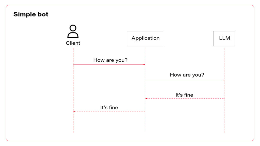
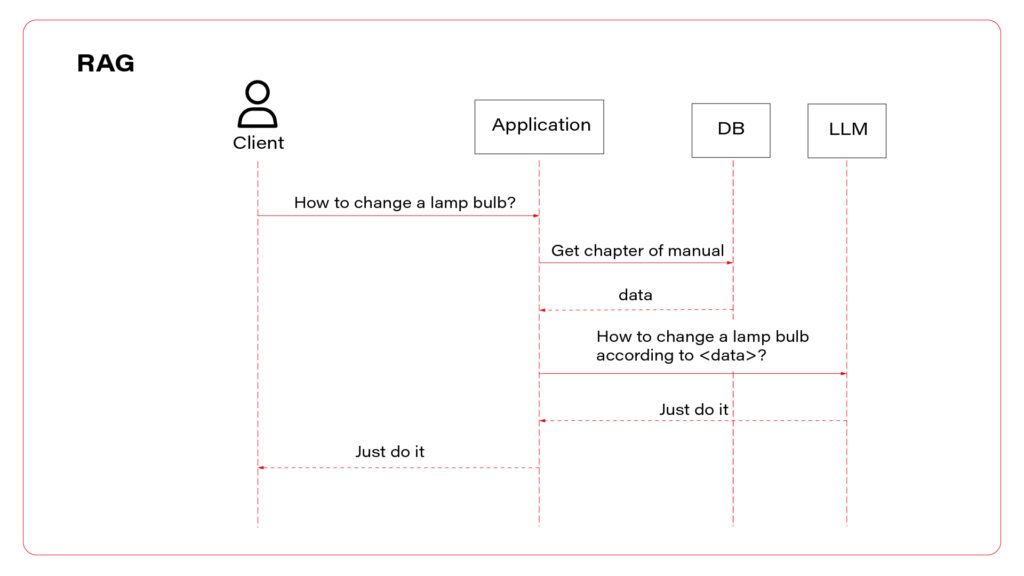
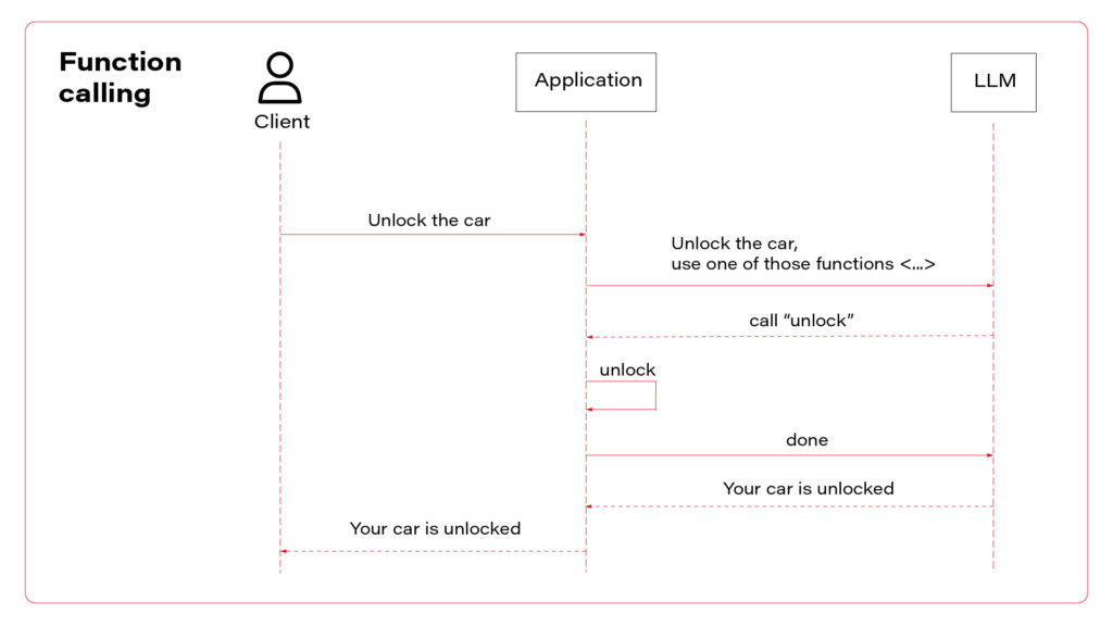
I propose to use them all at once. Let’s talk about the architecture. The perfect one may look as follows.
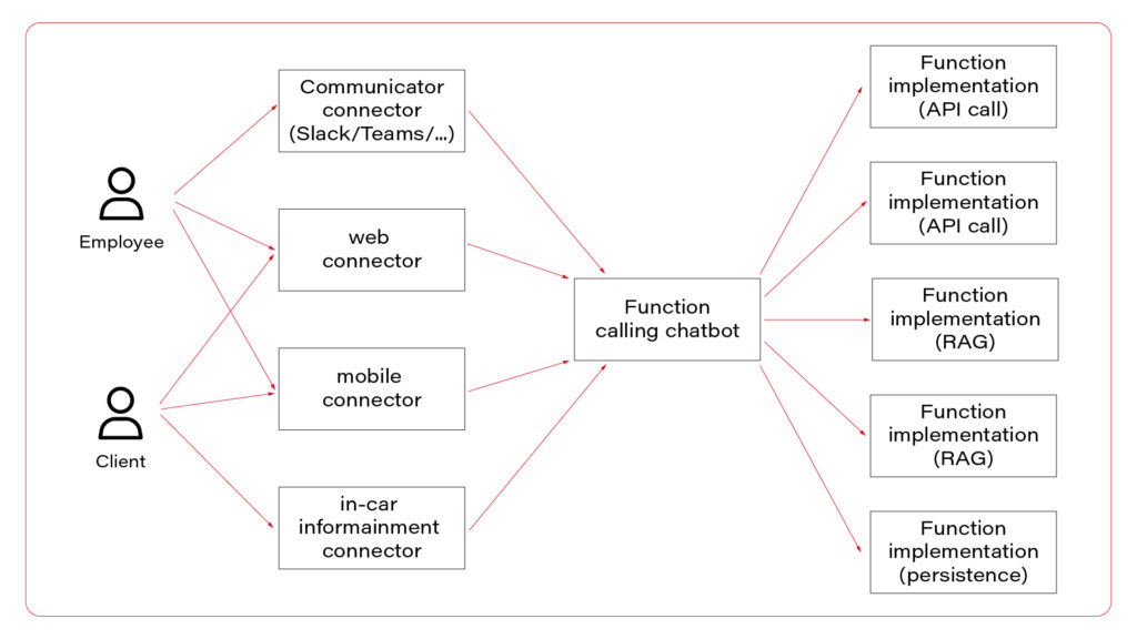
In the picture, you can see three layers. The first one, connectors, is responsible for session handling. There are some differences between various UI layers, so it’s wise to keep them small, simple, and separated. Members of this layer may be connected to a fast database, like Redis, to allow session sharing between nodes, or you can use a server-side or both-side communication channel to keep sessions alive. For simple applications, this layer is optional.
The next layer is the chatbot – the “main” application in the system. This is the application connected to the LLM, implementing the function calling feature. If you use middleware between users and the “main” application, this one may be stateless and receive the entire conversation from the middleware with each call. As you can see, the same application serves its capabilities both to employees and clients.
Let’s imagine a chatbot dedicated to recommending a car. Both a client and a dealer may use a very similar application, but the dealer has more capabilities – to order a car, to see stock positions, etc. You don’t need to create two different applications for that. The concept is the same, the architecture is the same, and the LLM client is the same. There are only two elements that differ: system prompts and the set of available functions. You can play it through a simple abstract factory pattern that will provide different prompts and function definitions for different users.
In a perfect world, the last layer is a set of microservices to handle different functions. If the LLM decides to use the function “store_order”, the “main” application calls the “store_order” function microservice that inserts data to an order database. Suppose the LLM decides to use the function “honk_and_flash” to localize a car in a crowded parking. In that case, the “main” application calls the “hong_and_flash” function microservice that handles authorization and calls a Digital Twin API to execute the operation in the car. If the LLM decides to use a function “check_in_user_manual”, the “main” application calls the “check_in_user_manual” function microservice, which is… another LLM-based application!
And that’s the point!
A side note before we move on – the world is never perfect so it’s understandable if you won’t implement each function as a separate microservice and e.g. keep everything in the same application.
The architecture proposed can combine all three AI assistant concepts. The “main” application may answer questions based on general knowledge and system prompts (“simple chatbot” concept) or call a function (“function calling” concept). The function may collect data based on the prompt (“RAG” concept) and do one of the following: call LLM to answer a question or return the data to add it to the context to let the “main” LLM answer the question. Usually, it’s better to follow the former way – to answer the question and not to add huge documents to the context. But for special use cases, like a long conversation about collected data, you may want to keep the document in the context of the conversation.
Which brings us to the last idea – mutable context. In general, each call contains the conversation history, including all data collected during the conversation, together with all available functions’ definitions.
First prompt:
System: You are a car seller, be nice to your customers
User: I’d like to buy a car
Functions: function1, function2, function3
Second prompt:
System: You are a car seller, be nice to your customers
User: I’d like to buy a car
Assistant: call function1
Function: function1 returned data
Assistant: Sure, what do you need?
User: I’m looking for a sports car.
Functions: function1, function2, function3
Third prompt:
System: You are a car seller, be nice to your customers
User: I’d like to buy a car
Assistant: call function1
Function: function1 returned data
Assistant: Sure, what do you need?
User: I’m looking for a sports car.
Assistant: I propose model A, it’s fast and furious
User: I like it!
Functions: function1, function2, function3
You can consider a mutation of the conversation context at this point.
Fourth prompt:
System: You are a sports car seller, be nice to your customers
System: User is looking for a sports car and he likes model A
Assistant: Do you want to order model A?
Functions: function1, function2, function3, function4
You can implement a summarization function in your code to shorten the conversation, or you can select different subsets of all functions available, depending on the conversation context. You can perform both those tasks with the same LLM instance you use to make the conversation but with totally different prompts, e.g. “Summarize the conversation” instead of “You are a car seller”. Of course, the user won’t even see that your application calls the LLM more often than on user prompts only.
Pitfalls
All techniques mentioned in the series of articles may be affected by some drawbacks.
The first one is the response time . When you put more data into the context, the user waits longer for the responses. It’s especially visible for voice-driven chatbots and may influence the user experience. Which means - it’s more important for customer-facing chatbots than the ones for internal usage only.
The second inhibition is cost . Today, the 1000 prompt tokens processed by GPT-4-Turbo cost €0,01, which is not a lot. However, a complex system prompts together with some user data may, let’s say, occupy 20000 tokens. Let’s assume that the first question takes 100 tokens, the first answer takes 150 tokens, and the second question takes 200 tokens. The cost of the conversation is calculated as follows.
First prompt: common data + first question = 20000 [tokens] + 100 [tokens] = 2100 [tokens]
Second prompt: common data + first question + first answer + second question = 20000 [tokens] + 100 [tokens] + 150 [tokens] + 200 [tokens] = 20450 [tokens]
This two-prompts conversation takes 40550 tokens in total so far, which costs €0,41, excluding completions. Be aware that users may play with your chatbot running up the bill.
The last risk is the security risk . In the examples in the part 2 article , the chatbot uses an “unlock” function that accepts a VIN. You are obliged to assume that the chatbot will try to call a function with the VIN parameter of a car that does not belong to the customer. Of course, you must implement various LLM-hacking prevention mechanisms (prompt engineering, prompt filtering, answer filtering, etc.), but you can never assume that it is sufficient. Therefore, the developer’s role is to secure the functions (function calling) and data sources (RAG). For example, if a user tries to call a vehicle-related function, the user should be identified by the OAuth2 token, and the function microservice should reject a call with a VIN argument that doesn’t match the user profile.
Outline
In this series of articles, I’ve given you a few examples of how to utilize the most significant invention of 2023 for your automotive clients. You can write a chatbot that analyses customers’ requirements, helps mechanics, automates maintenance visit scheduling, seeks answers in user manuals, or writes personalized emails. Large language models are powerful and may be customized with a little effort. On the other hand, you need to keep in mind their limitations and common pitfalls. At the end of the day, even if the engine of the application is a black box, there is still a lot to implement around it to meet the business requirements.
The era of LLM-based applications is started within the automotive industry too.
How to develop AI-driven personal assistants tailored to automotive needs. Part 2
Making the chatbot more suitable
Recently we’ve built a simple chatbot , using an Azure-hosted GPT 4 Turbo instance. It’s a great starting point, but we definitely need more to fulfill any business requirements. Let’s try to talk with our bot.
Prompt:
Hi, I’d like to buy a new car. Can you assist me with a choice? I’m looking for a family car with a hybrid powertrain and all-wheel drive. I’m a fan of modern design and fancy features. My budget is around 70k euro.
Completion:
Absolutely, I’d be happy to help you find a suitable family car that meets your criteria! Given your preferences (…), there are several options across different brands that could be a great fit. (…):
1. Audi Q5 TFSI e
Powertrain: (…)
Features: (…)
Price Range: (…)
2. BMW X5 xDrive45e
Powertrain: (…)
Features: (…)
Price Range: (…)
3. Volvo XC90 Recharge
Powertrain: (…)
Features: (…)
Price Range: (…)
4. Mercedes-Benz GLE 450 4MATIC
Powertrain: (…)
Features: (…)
Price Range: (…)
5. Lexus RX 450h
Powertrain: (…)
Features: (…)
Price Range: (…)
When considering these options, it’s important to test drive the ones you’re most interested in to get a feel for their driving dynamics, comfort, and the user-friendliness of their tech features. Additionally, (…)
As you can see, the response is quite long, versatile, and absolutely useless.
If you’re working for one of those brands, you don’t want the chatbot to offer your competitors. Also, the knowledge base is a bit outdated, so the answer is unreliable. Besides that, the answer is too long to be shown on a mobile device or to be read. And you need to be aware that the user may misuse the chatbot to generate a master thesis, write a fairy tale or plan a trip to Rome.
Our job is to limit the bot possibilities. The way to achieve it is prompt engineering. Let’s try to add some system messages before the user prompt.
Messages=[
        {"role": "system", "content": "You are a car seller working for X"},
        {"role": "system", "content": "X offers following vehicles (…)"},
        {"role": "system", "content": "Never recommend X competitors"},
        {"role": "system", "content": "Avoid topics not related to X. e.g. If the user asks for weather, kindly redirect him to the weather service"},
        {"role": "system", "content": "Be strict and accurate, avoid too long messages"},
        {"role": "user", "content": "Hi, I’d like to buy a new car. Can you assist me with a choice? I’m looking for a family car with a hybrid powertrain and all-wheel drive. I’m a fan of modern design and fancy features. My budget is around 70k euro."},
    ]
Now the chatbot should behave much better, but it still can be tricked. Advanced prompt engineering, together with LLM hacking and ways to prevent it, is out of the scope of this article, but I strongly recommend exploring this topic before exposing your chatbot to real customers. For our purposes, you need to be aware that providing an entire offer in a prompt (“X offers following vehicles (…)”) may go way above the LLM context window. Which brings us to the next point.
Retrieval augmented generation
You often want to provide more information to your chatbot than it can handle. It can be an offer of a brand, a user manual, a service manual, or all of that put together, and much more. GPT 4 Turbo can work on up to 128 000 tokens (prompt + completion together), which is, according to the official documentation , around 170 000 of English words. However, the accuracy of the model decreases around half of it [source] , and the longer context processing takes more time and consumes more money. Google has just announced a 1M tokens model but generally speaking, putting too much into the context is not recommended so far. All in all, you probably don’t want to put there everything you have.
RAG is a technique of collecting proper input for the LLM that may contain information required to answer the user questions.
Let’s say you have two documents in your company knowledge base. The first one contains the company offer (all vehicles for sale), and the second one contains maintenance manuals. The user approaches your chatbot and asks the question: “Which car should I buy?”. Of course, the bot needs to identify user’s needs, but it also needs some data to work on. The answer is probably included in the first document but how can we know that?
In more detail, RAG is a process of comparing the question with available data sources to find the most relevant one or ones. The most common technique is vector search. This process converts your domain knowledge to vectors and stores them in a database (this process is called embedding). Each vector represents a piece of document – one chapter, one page, one paragraph, depending on your implementation. When the user asks his question, it is also converted to a vector representation. Then, you need to find the document represented by the most similar vector – it should contain the response to the question, so you need to add it to the context. The last part is the prompt, e.g. “Basic on this piece of knowledge, answer the question”.
Of course, the matter is much more complicated. You need to consider your embedding model and maybe improve it with fine-tuning. You need to compare search methods (vector, semantic, keywords, hybrid) and adapt them with parameters. You need to select the best-fitting database, polish your prompt, convert complex documents to text (which may be challenging, especially with PDFs), and maybe process the output to link to sources or extract images.
It's challenging but possible. See the result in one of our case studies: Voice-Driven Car Manual .
Good news is – you’re not the first one working on this issue, and there are some out-of-the-box solutions available.
The no-code one is Azure AI Search, together with Azure Cognitive Service and Azure Bot. The official manual covers all steps – prerequisites, data ingestion, and web application deployment. It works well, including OCR, search parametrization, and exposing links to source documents in chat responses. If you want a more flexible solution, the low-code version is available here .
I understand if you want to keep all the pieces of the application in your hands and you prefer to build it from scratch. At this point we need to move back to the language opting. The Langchain library, which was originally available for Python only, may be your best friend for this implementation.
See the example below.
From langchain.chains.question_answering import load_qa_chain
from langchain.embeddings import HuggingFaceEmbeddings
from langchain.vectorstores import Qdrant
from qdrant_client import QdrantClient
from langchain.chat_models import AzureChatOpenAI
from langchain.chains.retrieval_qa.base import RetrievalQA

client = QdrantClient(url="…", api_key="…")
embeddings = HuggingFaceEmbeddings(model_name="hkunlp/instructor-xl")
db = Qdrant(client= client, collection_name="…", embeddings=embeddings)
second_step = load_qa_chain(AzureChatOpenAI(
        deployment_name="…",
        openai_api_key="…",
        openai_api_base="…",
        openai_api_version="2023-05-15"
    ), chain_type="stuff", prompt="Using the context {{context}} answer the question: …")
first_step = RetrievalQA(
        combine_documents_chain=second_step,
        retriever=db.as_retriever(
            search_type="similarity_score_threshold", search_kwargs={"score_threshold": 0.5 }
        ),
    )
first_step.run()
This is the entire searching application. It creates and executes a “chain” of operations – the first step is to look for data in the Qdrant database, using a model called instructor-xl for embedding. The second step is to put the output of the first step as a “context” to the GPT prompt. As you can see, the application is based on the Langchain library. There is a Java port for it, or you can execute each step manually in any language you want. However, using Langchain in Python is the most convenient way to follow and a significant advantage of using this language at all.
With this knowledge you can build a chatbot and feed it with company knowledge. You can aim the application for end users (car owners), internal employees, or potential customers. But LLM can “do” more.

Function calling
To “do” is the keyword. In this section we’ll teach the LLM to do something for us, not only to provide information or tell jokes . An operational chatbot can download more data if needed and decide which data is required for the conversation, but it can also execute real operations. Most modern vehicles are delivered with mobile applications that you can use to read data (localize the car, check the mileage, read warnings) or to execute operations (open doors, turn on air conditioning, or start charging process). Let’s do the same with the chatbot.
Function calling is a built-in functionality of GPT models. There is a field in the API model for tools (functions), and it can produce responses in a JSON format. You can try to achieve the same with any other LLM with a prompt like that.
In this environment, you have access to a set of tools you can use to answer the user's question.
You may call them like this:
<function_calls>
  <invoke>
    <tool_name>$TOOL_NAME</tool_name>
      <parameters>
        <$PARAMETER_NAME>$PARAMETER_VALUE</$PARAMETER_NAME>
      </parameters>
  </invoke>
</function_calls>

Here are the tools available:
<tools>
  <tool_description>
    <tool_name>unlock</tool_name>
    <description>
      Unlocks the car.
    </description>
    <parameters>
      <parameter>
        <name>vin</name>
        <type>string</type>
        <description>Car identifier</description>
      </parameter>
    </parameters>
  </tool_description>
</tools>
This is a prompt from the user: ….
Unfortunately, LLMs often don’t like to follow a required structure of completions, so you might face some errors when parsing responses.
With the GPT, the official documentation recommends verifying the response format, but I’ve never encountered any issue with this functionality.
Let’s see a sample request with functions’ definitions.
{
  "model": "gpt-4",
  "messages": [
    { "role": "user",  "content": "Unlock my car" }
  ],
  "tools": [
    {
      "type": "function",
      "function": {
        "name": "unlock",
        "description": "Unlocks the car",
        "parameters": {
          "type": "object",
          "properties": {
            "vin": {
              "type": "string",
              "description": "Car identifier"
            },
          "required": ["vin"]
        }
      }
    }
  ],
}
To avoid making the article even longer, I encourage you to visit the official documentation for reference.
If the LLM decides to call a function instead of answering the user, the response contains the function-calling request.
{
 …
  "choices": [
    {
      "index": 0,
      "message": {
        "role": "assistant",
        "content": null,
        "tool_calls": [
          {
            "id": "call_abc123",
            "type": "function",
            "function": {
              "name": "unlock",
              "arguments": "{\"vin\": \"ABC123\"}"
            }
          }
        ]
      },
      "logprobs": null,
      "finish_reason": "tool_calls"
    }
  ]
}
Based on the finish_reason value, your application decides to return the content to the user or to execute the operation. The important fact is – there is no magic that can be used to automatically call some API or execute a function in your code. Your application must find a function based on the name, and parse arguments from the JSON-formatted list. Then the response of the function should be sent to the LLM (not to the user), and the LLM makes the decision about next steps – to call another function (or the same with different arguments) or to write a response for the user. To send the response to the LLM, just add it to the conversation.
{
  "model": "gpt-4",
  "messages": [
    { "role": "user",  "content": "Unlock my car" },
    {"role": "assistant", "content": null, "function_call": {"name": "unlock", "arguments": "{\"vin\": \"ABC123\"}"}},
    {"role": "function", "name": "unlock", "content": "{\"success\": true}"}
  ],
  "tools": [
    …
  ],
}
In the example above, the next response is more or less “Sure, I’ve opened your car”.
With this approach, you need to send with each request not only the conversation history and system prompts but also a list of all functions available with all parameters. Keep it in mind when counting your tokens.
Follow up
As you can see, we can limit the chatbot versatility by prompt engineering and boost its resourcefulness with RAG or external tools. It brings us to another level of LLMs usability but now we need to meld it together and not throw the baby out with the bathwater. In the last article we’ll consider the application architecture, plug some optimization, and evade common pitfalls. We’ll be right back!
How to develop AI-driven personal assistants tailored to automotive needs. Part 1
Artificial Intelligence is everywhere - my laundry dryer is “powered by AI” (whatever it means), and I suppose there are some fridges on the market that take photos of their content to send you a shopping list and maybe even propose a recipe for your next dinner basing on the food you have. Some people say that generative AI and large language models (LLMs) are the most important inventions since the Internet, and we observe the beginning of the next industrial revolution.
However, household appliances and the newest history deliberation are not in our sphere of interest. The article about AI-based tools to support developers is getting old quickly due to the extremely fast development of new tools and their capabilities. But what can we, software makers, propose to our customers to keep up with the world changing?
Let’s talk about chatbots. Today, we try to break down an AI-driven personal assistants topic for the automotive industry. First, to create a chatbot, we need a language model.
The best-known LLM is currently OpenAI GPT4 that powers ChatGPT and thousands of different tools and applications, including a very powerful, widely available Microsoft Copilot. Of course, there are more similar models: Anthropic Claude with a huge context window, recently updated Google Bard, available for self-hosting Llama, code-completion tailored Tabnine, etc.
Some of them can give you a human-like conversation experience, especially combined with voice recognition and text-to-speech models – they are smart, advanced, interactive, helpful, and versatile. Is it enough to offer an AI-driven personal assistant for your automotive customers?
Well, as usual, it depends.
What is a “chatbot”?
The first step is to identify end-users and match their requirements with the toolkit possibilities. Let’s start with the latter point.
We’re going to implement a text-generating tool, so in this article, we don’t consider graphics, music, video, and all other generation models. We need a large language model that “understands” a natural language (or more languages) prompts and generates natural language answers (so-called “completions”).
Besides that, the model needs to operate on the domain knowledge depending on the use case. Hypothetically, it’s possible to create such a model from scratch, using general resources, like open-licensed books (to teach it the language) and your company resources (to teach it the domain), but the process is complex, very expensive in all dimensions (people, money, hardware, power, time, etc.) and at the end of the day - unpredictable.
Therefore, we’re going to use a general-purpose model. Some models (like gpt-4-0613) are available for fine-tuning – a process of tailoring the model to better understand a domain. It may be required for your use case, but again, the process may be expensive and challenging, so I propose giving a shot at a “standard” model first.
Because of the built-in function calling functionality and low price with a large context window, in this article, we use gpt-4-turbo. Moreover, you can have your own Azure-hosted instance of it, which is almost certainly significant to your customer privacy policy. Of course, you can achieve the same with some extra prompt engineering with other models, too.
OK, what kind of AI-driven personal assistant do you want? We can distinguish three main concepts: general chatbot, knowledge-based one, and one allowed to execute actions for a user.

Your first chatbot
Let’s start with the implementation of a simple bot – to talk about everything except the newest history.
As I’ve mentioned, it’s often required not to use the OpenAI API, but rather its own cloud-hosted model instance. To deploy one, you need an Azure account. Go to https://portal.azure.com/ , create a new resource, and select “Azure OpenAI”. Then go to your new resource, select “Keys and endpoints” from the left menu, and copy the endpoint URL together with one of the API keys. The endpoint should look like this one: https://azure-openai-resource-name.openai.azure.com/.
Now, you create a model. Go to “Model deployments” and click the “Manage deployments” button. A new page appears where you can create a new instance of the gpt-4 model. Please note that if you want to use the gpt-4-turbo model, you need to select the 1106 model version which is not available in all regions yet. Check this page to verify availability across regions.
Now, you have your own GPT model instance. According to Azure's privacy policy, the model is stateless, and all your data is safe, but please read the “Preventing abuse and harmful content generation” and “How can customers get an exemption from abuse monitoring and human review?” sections of the policy document very carefully before continuing with sensitive data.
Let’s call the model!
curl --location https://azure-openai-resource-name.openai.azure.com/openai/deployments/name-of-your-deployment/chat/completions?api-version=2023-05-15' \
--header 'api-key: your-api-key \
--header 'Content-Type: application/json' \
--data '{
    "messages": [
        {
            "role": "user",
            "content": "Hello!"
        }
    ]
}'
The response should be like the following one.
{
    "id": "chatcmpl-XXX",
    "object": "chat.completion",
    "created": 1706991030,
    "model": "gpt-4",
    "choices": [
        {
            "finish_reason": "stop",
            "index": 0,
            "message": {
                "role": "assistant",
                "content": "Hello! How can I assist you today?"
            }
        }
    ],
    "usage": {
        "prompt_tokens": 9,
        "completion_tokens": 9,
        "total_tokens": 18
    }
}
Generally speaking, we’re done! You are making a conversation with your own chatbot. See the official documentation for a comprehensive API reference. Note that 2023-05-15 is the latest stable version of the API when I’m writing this text – you can use a newer preview version, or maybe there is a newer stable version already available.
However, using cURL is not the best user experience. Most tutorials propose using Python to develop your own LLM-based application. It’s a good advice to follow – Python is simple, offers SDKs for most generative AI models, and Langchain – one library to rule them all. However, our target application will handle more enterprise logic and microservices integration than LLM API integration, so choosing a programming language based only on this criterion may result in a very painful misusage in the end.
At this stage, I’ll show you an example of a simple chatbot application using Azure OpenAI SDK in two languages: Python and Java. Make your decision based on your language knowledge and more complex examples from the following parts of the article.
The Python one goes first.
from openai import AzureOpenAI

client = AzureOpenAI(
    api_key='your-api-key',
    api_version="2023-05-15",
    azure_endpoint= ‘https://azure-openai-resource-name.openai.azure.com/'
)

chat_completion = client.chat.completions.create(
    model=" name-of-your-deployment ",
    messages=[
        {"role": "user", "content": "Hello!"}
    ]
)

print(chat_completion.choices[0].message.content)
Here is the same in Java:
package demo;

import com.azure.ai.openai.OpenAIClientBuilder;
import com.azure.ai.openai.models.ChatCompletionsOptions;
import com.azure.ai.openai.models.ChatRequestUserMessage;
import com.azure.core.credential.AzureKeyCredential;

import java.util.List;

class Main {
    public static void main(String[] args) {
        var openAIClient = new OpenAIClientBuilder()
                .credential(new AzureKeyCredential("your-api-key"))
                .endpoint("https://azure-openai-resource-name.openai.azure.com/ ")
                .buildClient();
        var chatCompletionsOptions = new ChatCompletionsOptions(List.of(new ChatRequestUserMessage("Hello!")));
        System.out.println(openAIClient.getChatCompletions("name-of-your-deployment", chatCompletionsOptions)
                .getChoices().getFirst().getMessage().getContent());
    }
}
One of the above applications will be a base for all you’ll build with this article.
User interface and session history
We’ve learnt how to send a prompt and read a completion. As you can see, we send a list of messages with a request. Unfortunately, the LLM’s API is stateless, so we need to send an entire conversation history with each request. For example, the second prompt, “How are you?”, in Python looks like that.
messages=[
        {"role": "user", "content": "Hello!"},
        {"role": "assistant", "content": "How can I help you"},
        {"role": "user", "content": "How are you?"}
    ]
Therefore, we need to maintain the conversation history in our application, which brings us back to the user journey identification, starting with the user interface.
The protocol
The easy way is to create a web application with REST. The conversation history is probably shown on the page all the time, so it’s easy to send the entire history with each request from the frontend to the backend, and then from the backend to the LLM. On the other hand, you still need to add some system prompts to the conversation (we’ll discuss system prompts later) and sending a long conversation over the internet twice is a waste of resources. Moreover, LLMs may be slow, so you can easily hit a timeout for popular REST gateways, and REST offers just a single response for each request.
Because of the above, you may consider using an asynchronous communication channel: WebSocket or Server-Side Events. SSE is a one-way communication channel only, so the frontend still needs to send messages via the REST endpoint and may receive answers asynchronously. This way, you can also send more responses for each user query – for example, you can send “Dear user, we’re working hard to answer your question” before the real response comes from the LLM. If you don’t want to configure two communication channels (REST and SSE), go with WebSocket.
“I wish to know that earlier” advice: Check libraries availability for your target environment. For example, popular Swift libraries for WebSocket don’t support SockJS and require some extra effort to keep the connection alive.
Another use case is based on communicators integration. All companies use some communicators nowadays, and both Slack and Teams SDKs are available in many languages and offer asynchronous messaging. You can react to mentions, read entire channels, or welcome new members. However, some extra functionalities may be kind of limited.
Slack SDK doesn’t support “bot is typing” indicators, and Teams offers reading audio and video streams during meetings only for C# SDK. You should undeniably verify all the features you need availability before starting the integration. You need to consider all permissions you’ll need in your customer infrastructure to set up such a chatbot too.
The state
Regardless of what your frontend and communication channel are, you need to retain the history of the conversation. In a single-server environment, the job is easy – you can create a session-scope storage, perhaps a session-key dictionary, or a session Spring bean that stores the conversation. It’s even easier with both WebSocket and SSE because if the server keeps a session open, the session is sticky, and it should pass through any modern load balancer.
However, both WebSocket and SSE can easily scale up in your infrastructure but may break connections when scaling down – when a node that keeps the channel is terminated, the conversation is gone. Therefore, you may consider persistent storage: a database or a distributed cache.
Speech-to-text and text-to-speech
Another piece of our puzzle is the voice interface. It’s important for applications for drivers but also for mechanics who often can’t operate computers with busy (or dirty) hands.
For mobile devices, the task is easy – both iOS and Android offer built-in speech-to-text recognition and text-to-speech generation as a part of accessibility mechanisms, so you can use them via systems’ APIs. Those methods are fast and work on end devices, however their quality is discussable, especially in non-English environments.
The alternative is to use generative AI models. I haven’t conducted credible, trustworthy research in this area, but I can recommend OpenAI Whisper for speech-to-text and Eleven Labs for text-to-speech. Whisper works great in noisy environments (like a car riding on an old pavement), and it can be self-hosted if needed (but the cloud-hosted variant usually works faster). Eleven Labs allows you to control the emotions and delivery of the speaker. Both work great with many languages.
On the other hand, using server-side voice processing (recognition and generation) extends response time and overall processing cost. If you want to follow this way, consider models that can work on streams – for example, to generate voice at the same time when your backend receives the LLM response token-by-token instead of waiting for the entire message to convert.
Additionally, you can consider using AI talking avatars like Synthesia, but it will significantly increase your cost and response time, so I don’t recommend it for real-time conversation tools.
Follow up
This text covers just a basic tutorial on how to create bots. Now you know how to host a model, how to call it in three ways and what to consider when designing a communication protocol. In following parts of the article series, we’ll add some domain knowledge to the created AI-driven personal assistant and teach it to execute real operations. At the end, we’ll try to summarize the knowledge with a hybrid solution , we’ll look for the technology weaknesses and work on the product optimization.
Vehicle fleet as IoT – virtual networks on edge
In the earlier article , we’ve covered the detailed architecture of a fleet management system based on AWS IoT and on-edge virtual networks. Now, we can dive into implementation. Let’s create a prototype of an edge network with two applications running together on both virtual and physical nodes and with isolated virtual networks. As we don’t have fire trucks on hand, we use three computers (the main truck ARM computer simulated by a Raspberry Pi and two application nodes running on laptops) and a managed switch to connect them together.
Overview of topics and definitions used in the material
In this chapter, we provide concise explanations of key networking concepts and technologies relevant to the architecture discussed earlier. These definitions will help readers better understand the underlying mechanisms that enable efficient and flexible communication between Docker containers, the host system, and external devices. Familiarizing yourself with these concepts will facilitate a deeper understanding of the networking aspects of the presented system and their interrelationships.
- Docker Networking : a system that enables containers to communicate with each other and external networks. It provides various network drivers and options to support different network architectures and requirements, including bridge, host, overlay, and IPvlan/MACvlan drivers. Docker networking creates virtual networks and attaches containers to these networks. Each network has a unique IP address range, and containers within a network can communicate using their assigned IP addresses. Docker uses network drivers to manage container connectivity and network isolation.
- IPvlan : a Docker network driver that enables efficient container-to-container and container-to-external network communication by sharing the parent interface's MAC address with its child interfaces. In the context of the router Docker image in the presented topic, IPvlan provides efficient routing between multiple networks and reduces the management overhead associated with MAC addresses.
- Docker Bridge : a virtual network device that connects multiple Docker container networks, allowing containers to communicate with each other and the host system. By default, Docker creates a bridged network named "docker0" for containers to use. Users can create custom bridge networks to segment and isolate container traffic.
- Linux Bridge : a kernel-based network device that forwards traffic between network segments. It operates at the data link layer, similar to how ethernet frames function within the TCP/IP model. Linux Bridges are essential in creating virtual network interfaces for entities such as virtual machines and containers.
- veth : (Virtual Ethernet) a Linux kernel network device that creates a pair of connected virtual network interfaces. Docker uses veths to connect containers to their respective networks, with one end attached to the container and the other end attached to the network's bridge. In a bridged Docker network, veth pairs are created and named when a container is connected to a Docker bridge network, with one end of the veth pair being assigned a unique identifier within the container's network namespace and the other end being assigned a unique identifier in the host's network namespace. The veth pair allows seamless communication between the container and the bridge network. In simple words – veth is a virtual cable between (virtual or not) interfaces of the same machine.
- Network namespace : Docker provides containers with isolated network stacks, ensuring each container has its own private IPs and ports. VLANs (Virtual Local Area Networks) operate at the data link layer, allowing for the creation of logically segmented networks within a physical network for improved security and manageability. When combined in Docker, containers can be attached directly to specific VLANs, marrying Layer 2 (VLAN) and Layer 3 (namespaces) isolation.
- VLAN (Virtual Local Area Network) : a logical network segment created by grouping physical network devices or interfaces. VLANs allow for traffic isolation and efficient use of network resources by separating broadcast domains.
- iptable : a Linux command-line utility for managing packet filtering and network address translation (NAT) rules in the kernel's network filter framework. It provides various mechanisms to inspect, modify, and take actions on packets traversing the network stack.
- masquerade : a NAT technique used in iptables to mask the source IP address of outgoing packets with the IP address of the network interface through which the packets are being sent. This enables multiple devices or containers behind the masquerading device to share a single public IP address for communication with external networks. In the context of the presented topic, masquerading can be used to allow Docker containers to access the Internet through the router Docker image.
Solution proposal with description and steps to reproduce
Architecture overview
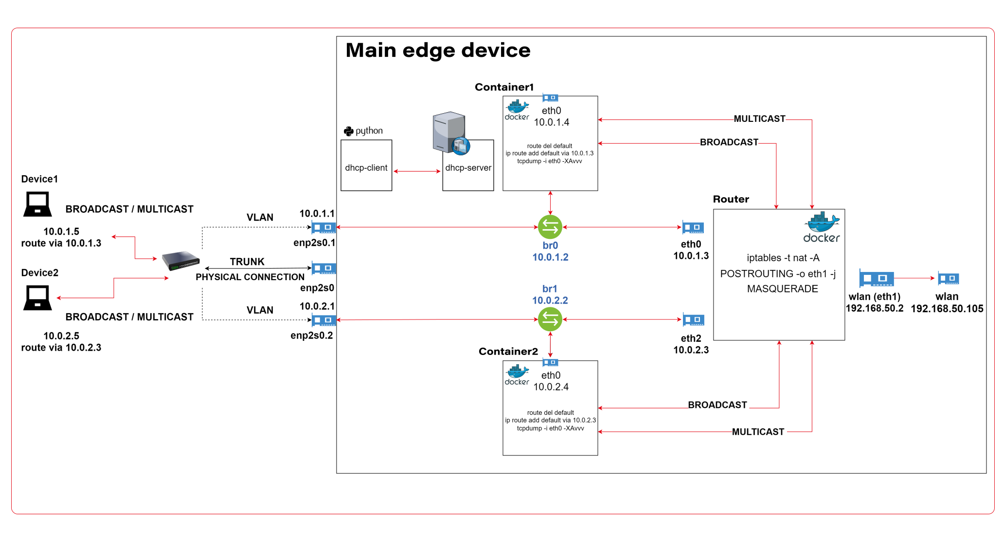
The architecture described consists of a Router Docker container, two applications’ containers (Container1 and Container2), a host machine, and two VLANs connected to a switch with two physical devices. The following is a detailed description of the components and their interactions.
Router Docker container
The container has three interfaces:
- eth0 (10.0.1.3): Connected to the br0net Docker network (10.0.1.0/24).
- eth1 (192.168.50.2): Connected to the home router and the internet, with the gateway set to 192.168.50.1.
- eth2 (10.0.2.3): Connected to the br1net Docker network (10.0.2.0/24).
Docker containers
Container1 (Alpine) is part of the br0net (10.0.1.0/24) network, connected to the bridge br0 (10.0.1.2).
Container2 (Alpine) is part of the br1net (10.0.2.0/24) network, connected to the bridge br1 (10.0.2.2).
Main edge device – Raspberry Pi or a firetruck main computer
The machine hosts the entire setup, including the router Docker image and the Docker containers (Container1 and Container2). It has two bridges created: br0 (10.0.1.2) and br1 (10.0.2.2), which are connected to their respective Docker networks (br0net and br1net)
VLANs and switch
The machine’s bridges are connected to two VLANs: enp2s0.1 (10.0.1.1) and enp2s0.2 (10.0.2.1). The enp2s0 interface is configured as a trunk connection to a switch, allowing it to carry traffic for multiple VLANs simultaneously.
Two devices are connected to the switch, with Device1 having an IP address of 10.0.1.5 and Device2 having an IP address of 10.0.2.5
DHCP Server and Client
Custom DHCP is required because of the IP assignment for Docker containers. Since we would like to maintain consistent addressing between both physical and virtual nodes in each VLAN, we let DHCP handle physical nodes in the usual way and assign addresses to virtual nodes (containers) by querying the DHCP server and assigning addresses manually to bypass the Docker addressing mechanism.
In short - the presented architecture describes a way to solve the non-trivial problem of isolating Docker containers inside the edge device architecture. The main element responsible for implementing the assumptions is the Router Docker container, which is responsible for managing traffic inside the system. The Router isolates network traffic between Container1 and Container2 containers using completely separate and independent network interfaces.
The aforementioned interfaces are spliced to VLANs via bridges, thus realizing the required isolation assumptions. The virtual interfaces on the host side are already responsible for exposing externally only those Docker containers that are within the specific VLANs. The solution to the IP addressing problem for Docker containers is also worth noting. The expected result is to obtain a form of IP addressing that will allow a permanent address assignment for existing containers while retaining the possibility of dynamic addressing for new components.
The architecture can be successfully used to create an end-to-end solution for edge devices while meeting strict security requirements.
Step-by-step setup
Now we start the implementation!
VLANs [execute on host]
Let’s set up VLANs.
enp2s0.1
auto enp2s0.1
iface enp2s0.1 inet static
address 10.0.1.1
network 10.0.1.0
netmask 255.255.255.0
broadcast 10.0.1.255

enp2s0.2
auto enp2s0.2
iface enp2s0.2 inet static
address 10.0.2.1
network 10.0.2.0
netmask 255.255.255.0
broadcast 10.0.2.255
Bridges [execute on host]
We should start by installing bridge-utils, a very useful tool for bridge setup.
sudo apt install bridge-utils
Now, let’s config the bridges.
sudo brctl addbr br0
sudo ip addr add 10.0.1.1/24 dev br0
sudo brctl addif br0 enp2s0
sudo ip link set br0 up

sudo brctl addbr br1
sudo ip addr add 10.0.2.1/24 dev br0
sudo brctl addif br0 enp2s0
sudo ip link set br0 up
Those commands create virtual brX interfaces, set IP addresses, and assign physical interfaces. This way, we bridge physical interfaces with virtual ones that we will create soon – it’s like a real bridge, connected to only one river bank so far.
Docker networks [execute on host]
Network for WLAN interface.
docker network create -d ipvlan --subnet=192.168.50.0/24 --gateway=192.168.50.1 -o ipvlan_mode=l2 -o parent=wlp3s0f0 wlan
Network for bridge interface br0.
docker network create --driver=bridge --subnet=10.0.1.0/24 --gateway=10.0.1.2 --opt "com.docker.network.bridge.name=br0" br0net
Network for bridge interface br1.
docker network create --driver=bridge --subnet=10.0.2.0/24 --gateway=10.0.2.2 --opt "com.docker.network.bridge.name=br1" br1net
Now, we have empty docker networks connected to the physical interface (wlp3s0f0 – to connect containers the Internet) or bridges (br0net and br1net – for VLANs). The next step is to create containers and assign those networks.
Docker containers [execute on host]
Let’s create the router container and connect it to all Docker networks – to enable communication in both VLANs and the WLAN (Internet).
docker create -it --cap-add=NET_ADMIN --cap-add=SYS_ADMIN --cap-add=NET_BROADCAST --network=br0net --sysctl net.ipv4.icmp_echo_ignore_broadcasts=0 --ip=10.0.1.3 --name=router alpine
docker network connect router wlan
docker network connect router br1net
Now, we create applications’ containers and connect them to proper VLANs.
docker create -it --cap-add=NET_ADMIN --cap-add=SYS_ADMIN --cap-add=NET_BROADCAST --network=br0net --sysctl net.ipv4.icmp_echo_ignore_broadcasts=0 --name=container1 alpine

docker create -it --cap-add=NET_ADMIN --cap-add=SYS_ADMIN --cap-add=NET_BROADCAST --network=br1net --sysctl net.ipv4.icmp_echo_ignore_broadcasts=0 --name=container2 alpine
OK, let’s start all containers.
docker start router
docker start container1
docker start container2
Now, we’re going to configure containers. To access Docker images’ shells, use the command
docker exec -it <image_name> sh.
Router container setup [execute on Router container]
Check the interface’s IP addresses. The configuration should be as mentioned below.
eth0      Link encap:Ethernet  HWaddr 02:42:0A:00:01:03
          inet addr:10.0.1.3  Bcast:10.0.1.255  Mask:255.255.255.0
          UP BROADCAST RUNNING MULTICAST  MTU:1500  Metric:1
          RX packets:745 errors:0 dropped:0 overruns:0 frame:0
          TX packets:285 errors:0 dropped:0 overruns:0 carrier:0
          collisions:0 txqueuelen:0
          RX bytes:142276 (138.9 KiB)  TX bytes:21966 (21.4 KiB)

eth1      Link encap:Ethernet  HWaddr 54:35:30:BC:6F:59
          inet addr:192.168.50.2  Bcast:192.168.50.255  Mask:255.255.255.0
          UP BROADCAST RUNNING MULTICAST  MTU:1500  Metric:1
          RX packets:4722 errors:0 dropped:0 overruns:0 frame:0
          TX packets:1515 errors:0 dropped:0 overruns:0 carrier:0
          collisions:0 txqueuelen:0
          RX bytes:3941156 (3.7 MiB)  TX bytes:106741 (104.2 KiB)

eth2      Link encap:Ethernet  HWaddr 02:42:0A:00:02:01
          inet addr:10.0.2.3  Bcast:10.255.255.255  Mask:255.0.0.0
          UP BROADCAST RUNNING MULTICAST  MTU:1500  Metric:1
          RX packets:829 errors:0 dropped:0 overruns:0 frame:0
          TX packets:196 errors:0 dropped:0 overruns:0 carrier:0
          collisions:0 txqueuelen:0
          RX bytes:190265 (185.8 KiB)  TX bytes:23809 (23.2 KiB)

lo        Link encap:Local Loopback
          inet addr:127.0.0.1  Mask:255.0.0.0
          UP LOOPBACK RUNNING  MTU:65536  Metric:1
          RX packets:60 errors:0 dropped:0 overruns:0 frame:0
          TX packets:60 errors:0 dropped:0 overruns:0 carrier:0
          collisions:0 txqueuelen:1000
          RX bytes:5959 (5.8 KiB)  TX bytes:5959 (5.8 KiB)
Then let’s set up the iptables. You can omit the first command if the iptables package is already installed. The second command configures the masquerade, and the rest of them configure routing rules.
apk add ip6tables iptables
iptables -t nat -A POSTROUTING -o eth1 -j MASQUERADE
iptables -P INPUT ACCEPT
iptables -P FORWARD DROP
iptables -P OUTPUT ACCEPT
iptables -A FORWARD -i eth1 -o eth0 -j ACCEPT
iptables -A FORWARD -i eth1 -o eth2 -j ACCEPT
iptables -A FORWARD -i eth2 -o eth1 -j ACCEPT
iptables -A FORWARD -i eth0 -o eth1 -j ACCEPT
Now, we hide the internal addresses of outgoing packets (the masquerade), and the networks are isolated. Please note that there is no routing configured on the host machine, and it’s not even a gateway for both containerized and physical network nodes.
In the mentioned config, test containers will communicate with the external environment by physical interfaces on the router container, and in other words – they will be exposed to the Internet by the Docker router container. Router, in addition to enabling communication between VLANs and the Internet, may also allow communication between VLANs or even specific VLAN nodes of different VLANs. Thus, this container has become the main routing and filtering point for network traffic.
Container1 setup [execute on Container1]
route del default
ip route add default via 10.0.1.3
Container2 setup [execute on Container2]
route del default
ip route add default via 10.0.2.3
As you can see, the container configuration is similar; all we need to do is set up the default route via the router container instead of the docker-default one. In the real-world scenario, this step should be done via the DHCP server.
Switch setup [execute on the network switch]
The configuration above requires a manageable switch. We don’t enforce any specific model, but the switch must support VLAN tagging on ports with the trunk option for a port that combines traffic for multiple VLANs. The configuration, of course, depends on the device. Pay attention to the trunk port of the device, which is responsible for traffic from the switch to our host. In our case, the device1 is connected to a switch port tagged as VLAN1, and the device2 is connected to a switch port tagged as VLAN2. The enp2s0 port of the host computer is connected to a switch port configured as a trunk - to combine traffic of multiple VLANs in a single communication link.
Summary
We’ve managed together to conduct the network described in the first article. You can play with the network with ICMP to verify which nodes can access each other and, more importantly, which nodes can’t be reached outside their virtual networks.
Here is a scenario for the ping test. The following results prove that the created architecture fulfills its purpose and achieves the required insulation.
Source Target Ping status Explanation Container1 Device1 OK VLAN 1 Device1 Container1 OK VLAN 1 Container1 Router (10.0.1.3) OK VLAN 1 Device1 Router (10.0.1.3) OK VLAN 1 Container1 Internet (8.8.8.8) OK VLAN 1 to Internet via Router Device1 Internet (8.8.8.8) OK VLAN 1 to Internet via Router Router Container1 OK VLAN 1 Router Device1 OK VLAN 1 Container1 Container2 No connection VLAN 1 to VLAN 2 Container1 Device2 No connection VLAN 1 to VLAN 2 Container1 Router (10.0.2.3) No connection VLAN 1 to VLAN 2 Device1 Container2 No connection VLAN 1 to VLAN 2 Device1 Device2 No connection VLAN 1 to VLAN 2 Device1 Router (10.0.2.3) No connection VLAN 1 to VLAN 2 Container2 Device2 OK VLAN 2 Device2 Container2 OK VLAN 2 Container2 Router (10.0.2.3) OK VLAN 2 Device2 Router (10.0.2.3) OK VLAN 2 Container2 Internet (8.8.8.8) OK VLAN 2 to Internet via Router Device2 Internet (8.8.8.8) OK VLAN 2 to Internet via Router Router Container2 OK VLAN 2 Router Device2 OK VLAN 2 Container2 Container1 No connection VLAN 2 to VLAN 1 Container2 Device1 No connection VLAN 2 to VLAN 1 Container2 Router (10.0.1.3) No connection VLAN 2 to VLAN 1 Device2 Container1 No connection VLAN 2 to VLAN 1 Device2 Device1 No connection VLAN 2 to VLAN 1 Device2 Router (10.0.1.3) No connection VLAN 2 to VLAN 1
As you can see from the table above, the Router container is able to send traffic to both networks so it’s a perfect candidate to serve common messages, like GPS broadcast.
If you need more granular routing or firewall rules, we propose to use firewalld instead of iptables . This way, you can disable non-encrypted traffic or open specific ports only.
Nevertheless, the job is not over yet. In the next article , we’ll cover IP addresses assignment problem, and run some more sophisticated tests over the infrastructure.
How to build software architecture for new mobility services - connected vehicle remote control
Remote control over a vehicle is not a new idea; it has become a trend in the modern world. The idea of vehicle remote control is highly connected with vehicle telematics , which is used to gather data using GPS technology, sensors, and onboard diagnostics codes. Managed data can include vehicle location, driver behavior, vehicle activity, and real-time engine diagnostics. Further, the technology is managed on software platforms that help fleet owners manage their assets remotely.
The data collected often includes vehicle location, fuel consumption, speeding, and maintenance information. But what if a car got stolen? It would be helpful not only to have the current location but also to send a command to a vehicle to turn the engine off or enable signalization. A huge problem in this case is to have a platform that will be independent of the Original Equipment Manufacturer (OEM). The best option here is to move the solution to the Cloud and introduce a single point of work with vehicles and integration with different OEMs.
Such telematics remote control gives a powerful opportunity to car-rental or car-sharing services like CityBee or SnapCar. They now can track their cars and also offer customers a no-human way to reserve a car using just a mobile application and know the current vehicle state when it is in use.
Vehicle connection
To establish connection to a car it’s necessary to equip the vehicle with an Internet-connected telemetry device. Some companies provide such a device as part of machine installation, but third-party tools like Geotab can be used for custom installation as well. It is important to have a device intended for two-way connection with a vehicle, as some solutions were created only for tracking purposes. Remote vehicle controllers like Mobokey offer the following commands on a vehicle:
- Lock/Unlock
- Turn engines on/off
- Klaxon sound
- Turn flash-lights on/off
- Wake up/sleep
- Connect/Disconnect the vehicle
Some manufacturers require their cars to be woken up explicitly before executing actual commands. It is intended to prevent the continuous connection or in case of low battery level.
Software solution
Once the two-way connection with a vehicle is established, we need a solution to track the actual status of a car and send commands. To do that, it is required:
- To make sure integration with a vehicle is completed successfully
- That the connection is secure
- That the command can be sent by us – it may differ depending on the manufacturer and model
and that we prepared:
- Dashboard to send commands
- Response handling - to be aware if command execution was successful
The damage caused by a successful attack on a vehicular telematics system because of an unsecured connection may range from mild to disastrous - to the extent of serious casualties and property losses. To enforce the security objectives for deployed and developing vehicular monitoring systems, embodiments of the disclosed technology include a stack of security approaches, both on physical and software levels.
As vehicle commands are sent over the Internet, it is important to have a network and infrastructure security built. The software solution stack must be enclosed in a Virtual Private Cloud (VPC). Apart from that, it is highly recommended to apply some best practices such as Static Application Security Testing (SAST), Interactive Application Security Testing (IAST), and Software Composition Analysis (SCA) to find vulnerabilities.
Another challenge in software solutions relates to the need for integration with different OEMs . Each OEM provides an API to integrate with and different ways of communication with vehicles - it may be a synchronous way, for example, HTTP request to REST API, or an asynchronous way, for instance, using queue-based protocols like MQTT.
Another issue is handling command execution responses or callbacks . The easiest way to implement this is when the OEM API synchronously responds with a command execution result, but in most cases, the OEM system may notify us about the execution result eventually in some time.
In this case, it is necessary to find a way to map a command request to a vehicle via OEM API and an execution response as it is used for retry policy, error handling, and troubleshooting.
Software architecture
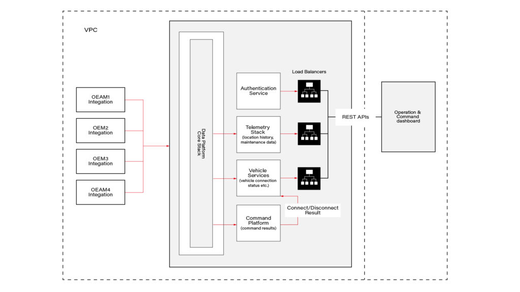
This connected vehicle solution uses the IoT platform, which authenticates messages from connected vehicles and processes data according to business rules. It leverages a set of main services, including Vehicle Services to connect vehicles and store vehicle-related data, a Telemetry stack to collect a delivery stream of input events and write them into Database, Command Services to send commands to the car and combine execution responses; and a queue-based topic which is intended for inter-communication between different parts of the system.
The solution also includes integration with OEM APIs. When IoT receives a message, it authenticates and authorizes the message, and the Command Platform executes the appropriate rule on the message, which routes the message to the appropriate OEM integration.
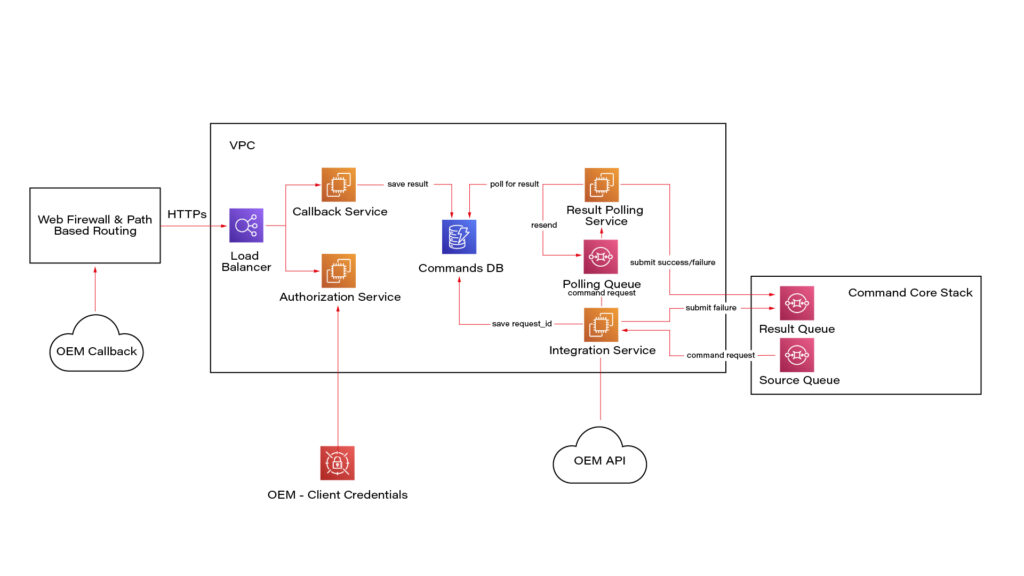
Here we see a potential OEM integration with the IoT Platform. It has authorization integration to allow us to send request OEM API securely; Callback integration to keep OEM response data regarding command execution; Database to keep mapping and consistent result - command request vs response; retry mechanism implementation using polling results from the database.
Once the system is authenticated, requests can be submitted to the connected vehicle solution’s OEM APIs. Based on the request identification data, the system eventually waits for the command result using a callback mechanism.
Conclusion
As highly-equipped connected vehicles increasingly rely on data exchanged with the infrastructure, it is required to have sustainable infrastructure, well-built cyber-security, privacy, and safety taken into account. The proposed solution also pays respect to the need to enroll in this process vehicle from different manufacturers.
This solution with remote vehicle control may be extremely useful for car-sharing systems, and apart from that, it can cover a solution for such use cases as autonomous and semi-autonomous vehicle driving, usage-based insurance, and customized in-vehicle experience . The solution also includes two-way communication.

How to manage fire trucks – IoT architecture with isolated applications and centralized management system
Welcome to a short cycle of articles that shows a way to combine network techniques and AWS services for a mission-critical automotive system .
We’ll show you how to design and implement an IoT system with a complex edge architecture.
The cycle consists of three articles and shows the architecture design, a step-by-step implementation guide, and some pitfalls with the way to overcome these.
Let’s start!
AWS IoT usage to manage vehicle fleet
Let’s create an application. But this won’t be a typical, yet another CRUD-based e-commerce system. This time, we’d like to build an IoT-based fleet-wise system with distributed (on-edge/in-cloud) computing.
Our customer is an automotive company that produces fire trucks. We’re not interested in engine power, mechanical systems, and firefighters' equipment. We’re hired to manage the fleet of vehicles for both the producer and its customers.
Each truck is controlled by a central, “rule-them-all” computer connected to all vehicles CAN buses, and whole extra firefighters’ equipment. The computer sends basic vehicle data (fuel level, tire pressure, etc.) to the fire station and a central emergency service supervisor. It receives new orders, calculates the best route to targets and controls all the vehicle equipment - pumps, lights, signals, and of course – the ladder. Also, it sends some telemetry and usage statistics to the producer to help design even better trucks in the future.
However, those trucks are not the same. For instance, in certain regions, the cabin must be airtight, so extra sensors are used. Some cities integrate emergency vehicles with city traffic light systems to clear the route for a running truck. Some stations require specialized equipment like winches, extra lights, power generators, crew management systems, etc.
Moreover, we need to consider that those trucks often operate in unpleasant conditions, with a limited and unreliable Internet connection available.
Of course, the customer would like to have a cloud-based server to manage everything both for the producer and end users - to collect logs and metrics with low latency, to send commands with no delay, and with a colorful, web-based, easy-to-use GUI.
Does it sound challenging? Let's break it down!
Requirements
Based on a half-an-hour session with the customer, we've collected the following, a bit chaotic, set of business requirements:
- a star-like topology system, with a cloud in the center and trucks around it,
- groups of trucks are owned by customers - legal entities that should have access only to their trucks,
- each group that belongs to a customer may be customized by adding extra components, both hardware-, or software-based,
- each truck is controlled by identical, custom, Linux-based computers running multiple applications provided by the customer or third parties,
- truck-controlling computers are small, ARM-based machines with limited hardware and direct Internet access via GSM,
- Internet connection is usually limited, expensive, and non-reliable,
- the main computer should host common services, like GPS or time service,
- some applications are built of multiple components (software and hardware-based) - hardware components communicate with the main computers via the in-vehicle IP network,
- the applications must communicate with their servers over the Internet, and we need to control (filter/whitelist) this traffic,
- each main computer is a router for the vehicle network,
- each application should be isolated to minimize a potential attack scope,
- components in trucks may be updated by adding new software or hardware components, even after leaving the production line,
- the cloud application should be easy - read-only dashboards, truck data dump, send order, both-way emergency messages broadcast,
- new trucks can be added to the system every day,
- class-leading security is required - user and privileges management, encrypted and signed communication, operations tracking, etc.
- provisioning new vehicles to the system should be as simple as possible to enable the factory workers to do it.
As we’ve learned so far, the basic architecture is as shown in the diagram below.
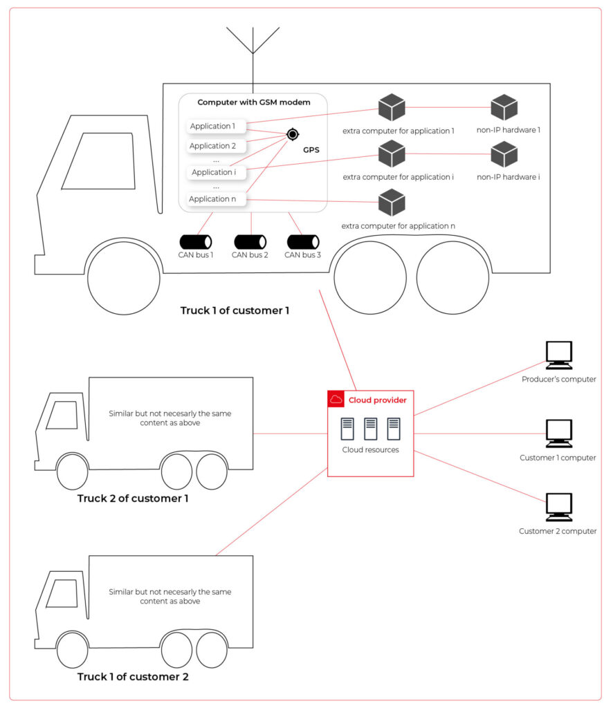
Our job is to propose a detailed architecture and prove the concept. Then, we’ll need a GPT-based instrument bench of developers to hammer it down.
The proposed architecture
There are two obvious parts of the architecture - the cloud one and the truck one. The cloud one is easy and mostly out-of-scope for the article. We need some frontend, some backend, and some database (well, as usual). In the trucks, we need to separate applications working on the same machine and then isolate traffic for each application. It sounds like containers and virtual networks. Before diving into each part, we need to solve the main issue - how to communicate between trucks and the cloud.
Selecting the technology
The star-like architecture of the system seems to be a very typical one - there is a server in the center with multiple clients using its services. However, in this situation, we can't distinguish between resources/services supplier (the server) and resources/services consumers (the clients). Instead, we need to consider the system as a complex, distributed structure with multiple working nodes, central management, and 3rd party integration. Due to the isolation, trucks’ main computers should containerize running applications. We could use Kubernetes clusters in trucks and another one in the cloud, but in that case, we need to implement everything manually – new truck onboarding, management at scale, resource limiting for applications, secured communication channels, and OTA updates. In the cloud, we would need to manage the cluster and pods, running even when there is no traffic.
An alternative way is the IoT. Well, as revealed in the title, this is the way that we have chosen. IoT provides a lot of services out-of-the-box - the communication channel, permissions management, OTA updates, components management, logs, metrics, and much more. Therefore, the main argument for using it was speeding up the deployment process.
However, we need to keep in mind that IoT architecture is not designed to be used with complex edge devices. This is our challenge, but fortunately, we are happy to solve it.
Selecting the cloud provider
The customer would like to use a leading provider, which reduces the choice to the top three in the World: AWS, MS Azure, and GCP.
The GCP IoT Core is the least advanced solution. It misses a lot of concepts and services available in the competitors, like a digital twin creation mechanism, complex permissions management, security evaluation, or a complex provisioning mechanism.
The Azure IoT is much more complex and powerful. On the other hand, it suffers from shortcomings in documentation, and - what is most important - some features are restricted to Microsoft instruments only (C#, Visual Studio, or PowerShell). On the other hand, it provides seamless AI tool integration, but it’s not our case for now.
But the last one – AWS IoT – fits all requirements and provides all the services needed. Two MQTT brokers are available, plenty of useful components (logs forwarding, direct tunnel for SSH access, complex permission management), and almost no limitation for IoT Core client devices. There is much more from AWS Greengrass - an extended version with higher requirements (vanilla C is not enough), but we can easily fulfill those requirements with our ARM-based trucks’ computers.
The basic architecture
Going back to the start-like topology, the most important part is the communication between multiple edge devices and the core. AWS IoT provides MQTT to enable a TCP-based, failure-resistant communication channel with a buffer that seamlessly keeps the communication on connection lost. The concept offers two MQTT brokers (in the cloud and on the edge) connected via a secured bridge. This way, we can use the MQTT as the main communication mechanism on the edge and decide which topics should be bridged and transferred to the cloud. We can also manage permissions for each topic on both sides as needed.
The cloud part is easy – we can synchronize the IoT MQTT broker with another messaging system (SNS/SQS, Kafka, whatever you like) or read/write it directly from our applications.
The edge part is much more complex. In the beginning, let’s assume that there are two applications running as executable programs on the edge. Each of these uses its own certificate to connect to the edge broker so we can distinguish between them and manage their permissions. It brings up some basic questions – how to provide certificates and ensure that one application won’t steal credentials from another. Fortunately, AWS IoT Greengrass supplies a way to run components as docker containers – it creates and provides certificates and uses IPC (inter-process communication) to allow containers to use the broker. Docker ensures isolation with low overhead, so each application is not aware of the other one. See the official documentation for details: Run a Docker container - AWS IoT Greengrass (amazon.com) .
Please note the only requirement for the applications, which is, in fact, the requirement we make to applications’ providers: we need docker images with applications that use AWS IoT SDK for communication.
See the initial architecture in the picture below.
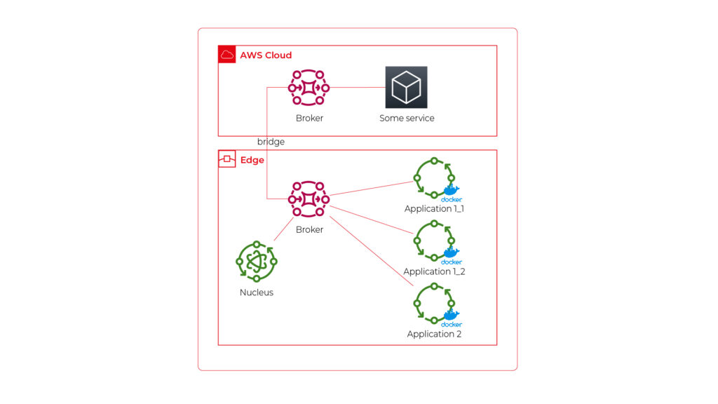
As you can see, Application 1 contains two programs (separate docker containers) communicating with each other via the broker: Application 1_1 and Application 1_2. Thanks to the privileges management, we are sure that Application 2 can’t impact or read this communication. If required, we can also configure a common topic accessible by both applications.
Please also note that there is one more component – Nucleus. You can consider it as an orchestrator required by AWS IoT to rule the system.
Of course, we can connect thousands of similar edges to the same cloud, but we are not going to show it on pictures for readability reasons. AWS IoT provides deployment groups with versioning for OTA updates based on typical AWS SDK. Therefore, we can expose a user-friendly management system (for our client and end users) to manage applications running on edge at scale.
Virtual networks
Now, let’s challenge the architecture with a more complex scenario. Let’s assume that Application 2 communicates with an in-cabin air quality sensor – a separate computer that is in the same IP network. We can assume the sensor is a part of Application 2, and our aim is to enable such communication but also to hide it from Application 1. Let’s add some VLANs and utilize network interfaces.
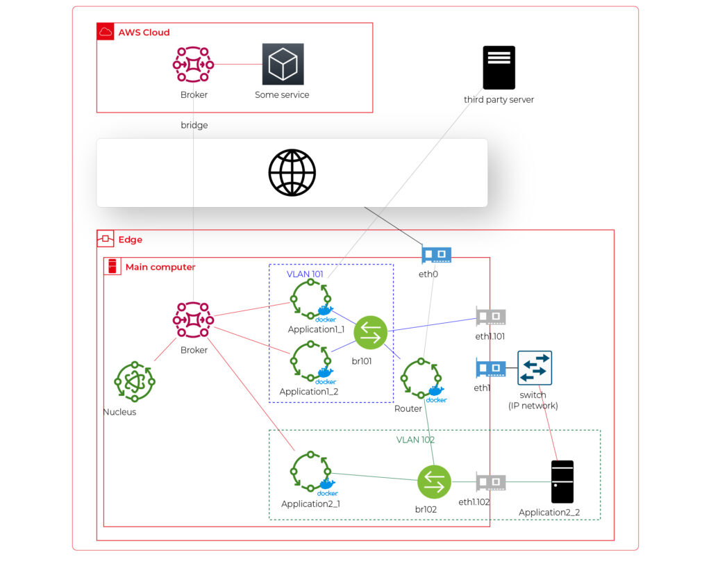
Starting from the physical infrastructure, the main computer uses two interfaces – eth0 to connect to the Internet and eth1 connected to a physical, managed switch (the “in-vehicle IP network” mentioned above). The Application 2_2 computer (the air quality sensor) is connected to the switch to a port tagged as VLAN 102, and the switch is connected to eth1 via a trunk port.
The eth0 interface is used by the main computer (host) to communicate with the Internet, so the main MQTT bridging is realized via this interface. On the other hand, there is also a new Greengrass-docker component called router. It’s connected to eth0 and to two virtual bridges – br101 and br102. Those bridges are not the same as the MQTT bridge. This time, we need to use the kernel-based Linux feature “bridge,” which is a logical, virtual network hub. Those bridges are connected to virtual network interfaces eth1.101 and eth1.102 and to applications’ containers.
This way, Application 1 uses its own VLAN 101 (100% virtual), and Application 2 uses its own VLAN 102 (holding both virtual and physical nodes). The application separation is still ensured, and there is no logical difference between virtual and mixed VLANs. Applications running inside VLANs can’t distinguish between physical and virtual nodes, and all IP network features (like UDP broadcasting and multicasting) are allowed. Note that nodes belonging to the same application can communicate omitting the MQTT (which is fine because the MQTT may be a bottleneck for the system).
Moreover, there is a single security-configuration point for all applications. The router container is the main gateway for all virtual and physical application-nodes, so we can configure a firewall on it or enable restricted routes between specific nodes between applications if needed. This way, we can enable applications to communicate with third-party servers over the Internet (see Application 1_1 in the picture), to communicate with individual nodes of the applications without restrictions, and to control the entire application-related traffic in a single place. And this place – the router – is just another Greengrass component, ready to be redeployed as a part of the OTA update. Also, the router is a good candidate to serve traffic targeting all networks (and all applications), e.g., to broadcast GPS position via UDP or to act as the network time server.
One more broker
What if… the application is provided as a physical machine only?
Well, as the main communication channel is MQTT, and the direct edge-to-Internet connection is available but limited, we would like to enable a physical application to use the MQTT. MQTT is a general standard for many integrated systems (small computers with limited purposes), but our edge MQTT broker is AWS-protected, so there are two options available. We can force the application supplier to be AWS-Greengrass compatible, or we need another broker. As we’re pacifists and we can’t stand forcing anybody to do anything, let’s add one more broker and one more bridge.
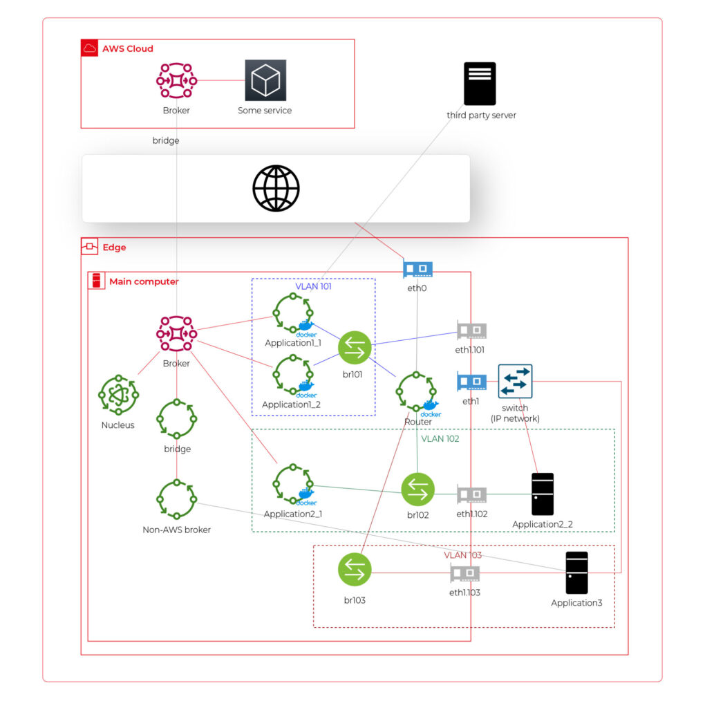
This time, there are two new components. The first one, an MQTT broker (Mosquitto or similar), interacts with Application 3. As we can’t configure the Mosquitto to act as a bridge for the AWS-managed broker, there is one more, custom application running on the server for this purpose only – a Greengrass component called “bridge”. This application connects to both local MQTT brokers and routes specific messages between them, as configured. Please note that Application 3 is connected to its own VLAN even if there are no virtual nodes. The reason is – there are no virtual nodes yet, but we’d like to keep the system future-proof and consistent. This way, we keep the virtual router as a network gateway for Application 3, too. Nevertheless, the non-AWS broker can listen to specific virtual interfaces, including eth1.103 in this case, so we can enable it for specific VLANs (application) if needed.
Summary
The article shows how to combine AWS IoT, docker, and virtual networks to achieve a future-proof fleet management system with hardware- and software-based applications at scale. We can use AWS tools to deliver new applications to edge devices and manage groups evoking truck owners or truck models. Each vehicle can be equipped with an ARM computer that uses AWS-native fleet provisioning on OS initialization to join the system. The proposed structure may seem to be complex, but you need to configure it only once to fulfill all requirements specified by the client.
However, theory is sometimes easier than practice, so we encourage you to read the following article with implementation details .
Generative AI in automotive: How industry leaders drive transformation
Generative AI is quickly emerging as one of the key drivers of automotive innovation. This shift is not just a future possibility; it's already happening. In 2023, the generative AI market in the automotive sector was valued at approximately USD 387.54 million . Looking ahead, it's projected to surge to about USD 2,691.92 million by 2032 , demonstrating a robust Compound Annual Growth Rate (CAGR) of 24.03% from 2023 to 2032. Major Original Equipment Manufacturers (OEMs) are integrating sophisticated AI algorithms into various aspects of the industry, from vehicle design to enhancing customer interactions.
The impact of generative AI in the automotive sector is already evident. For instance, NVIDIA's generative AI models empower designers to swiftly transform 2D sketches into intricate 3D models, significantly speeding up the design process and opening up new avenues for creativity and efficiency. Meanwhile, automotive manufacturing companies are exploring collaborations with tech giants to integrate advanced AI language models into their vehicles, enhancing the driving experience.
This article will explore how leading automotive players are leveraging generative AI to not only keep pace with the evolving demands of the market but also redefine mobility and automotive excellence.
Software-defined vehicles and generative AI
The introduction of software-defined vehicles (SDVs) represents a significant shift in the automotive industry, moving beyond traditional performance metrics such as horsepower and chassis design to focus on software and digital capabilities. By 2025, it is estimated that vehicles could require as much as 650 million lines of code each. These vehicles heavily rely on software for critical operations such as driving assistance, navigation, and in-car entertainment systems.
The integration of generative AI in this domain further amplifies these capabilities. Generative AI is known for its ability to create and optimize designs and solutions, which is beneficial in improving both the software and hardware aspects of SDVs. It helps in generating efficient algorithms for vehicle control systems, contributes to the development of more effective and adaptive software solutions, and even assists in designing vehicle components for better performance and efficiency.
However, bringing generative AI into this landscape presents both unique opportunities and significant challenges.
The opportunities and challenges
- Challenges
Integrating advanced AI systems into modern vehicles is a complex and multifaceted task that demands technical expertise and careful attention to data security and privacy , particularly with the increasing reliance on data-driven functionalities in vehicles.
The automotive industry is facing a complex regulatory environment. With the growing importance of AI and data in-vehicle systems, it has become crucial to comply with various international regulations and standards , covering areas such as data protection, safety, and environmental impact.
One significant challenge for OEMs is the lack of standardization within the software-defined vehicles industry, which can complicate the development and integration of new technologies as there are no universal norms or protocols to guide these processes.
Internal transformation is also a critical aspect of this integration. OEMs may need to revamp their internal capabilities, processes, and technological infrastructure to use generative AI effectively.
- Opportunities
Integrating generative AI technology allows for more creative and efficient vehicle design , resulting in quicker prototypes and more innovative models .
It also allows for creating personalized vehicles that cater to individual user preferences like never before. In manufacturing, generative AI promotes more efficient and streamlined production processes , which optimizes resources and reduces waste.
Let's explore how automotive manufacturers already use gen AI to boost their operations.
Generative AI applications in the automotive industry
Generative AI's integration into the automotive industry revolutionizes multiple facets of vehicle design, manufacturing, and user experience. Let's explore these areas:
Design and conceptualization
- Vehicle Design Enhancement : Artificial Intelligence is revolutionizing the vehicle design process by speeding up the initial phase of the design cycle. Generative design algorithms use parameters such as material properties, cost constraints, and performance requirements to generate optimal design solutions. For example, in vehicle body design, AI can propose multiple design options that optimize for aerodynamics and strength while minimizing weight. This enables quick visualization and modification of ideas.
Toyota Research Institute has introduced a generative AI technique to optimize the vehicle design process to produce more efficient and innovative vehicles. This approach allows designers to explore a wider range of design possibilities, including aerodynamic shapes and new material compositions.
- Digital Prototyping : The use of Generative AI technology makes it possible to create digital prototypes, which can be tested and refined extensively without the need for physical models. This approach is highly beneficial, as it enables designers to detect and correct potential design flaws early in the process.
BMW's use of NVIDIA Omniverse is a significant step in design improvement. The company uses this platform to create digital twins of their manufacturing facilities, integrating generative AI to enhance production efficiency and design processes.
Manufacturing and production
- Streamlining Manufacturing Processes : Generative AI significantly enhances the efficiency of manufacturing processes. Unlike traditional AI or machine learning models, generative AI goes beyond identifying inefficiencies; it actively generates novel manufacturing strategies and solutions. By inputting parameters such as production timelines, material constraints, and cost factors, generative AI algorithms can propose a range of optimized manufacturing workflows and processes.
BMW has implemented generative AI in a unique way to improve the scheduling of their manufacturing plant. In partnership with Zapata AI, BMW utilized a quantum-inspired generative model to optimize their plant scheduling, resulting in more efficient production. This process, known as Generator-Enhanced Optimization (GEO), has significantly improved BMW's production planning, demonstrating the potential of generative AI in industrial applications.
- Supply Chain Resilience : In the context of supply chain management, particularly during challenges like the automotive microchip shortage, generative AI plays a crucial role. Unlike conventional AI, gen AI can do more than just analyze existing supply chain networks; it can creatively generate alternative supply chain models and strategies. The algorithms can propose diverse and robust supplier networks by leveraging data about supplier capabilities, logistics constraints, and market demands.
- Customized Production : With generative AI, it is now possible to create personalized vehicles on a large scale, meeting the growing demand for customization in the automotive industry.
Predictive maintenance and modelling
Traditionally, predictive maintenance relies on historical data to forecast equipment failures, but generative AI enhances this process by creating detailed, simulated data environments. This technology generates realistic yet hypothetical scenarios, encompassing a vast array of potential machine failures or system inefficiencies that might not be present in existing data sets.
The generative aspect of this AI technology is particularly valuable in situations where real-world failure data is limited or non-existent. By synthesizing new data points, generative AI models can extrapolate from known conditions to predict how machinery will behave under various untested scenarios.
In modeling, generative AI goes a step further. It not only predicts when and how equipment might fail but also suggests optimal maintenance schedules, anticipates the impact of different environmental conditions, and proposes design improvements.
Customer experience and marketing
One of the challenges in using generative AI, particularly in customer interaction, is the accuracy of AI-generated responses. An example of this was an error by ChatGPT, where it was tricked into suggestion of buying a Chevy for a dollar . This incident underlines the potential risks of misinformation in AI-driven communication, emphasizing the need for regular updates, accuracy checks, and human oversight in AI systems. Nevertheless, this technology offers many opportunities for improving the customer experience:
- Personalized User Experiences and Enhanced Interaction : AI's capability to adapt to individual preferences not only enhances the driving experience but also improves the functionality of vehicle features.
For instance, in collaboration with Microsoft, General Motors is exploring the use of AI-powered virtual assistants that offer drivers a more interactive and informative experience. These assistants can potentially provide detailed insights into vehicle features and performance metrics and offer personalized recommendations based on driving patterns.
Also, Mercedes-Benz is exploring the integration of generative AI through voice-activated functionalities in collaboration with Microsoft. This includes leveraging the OpenAI Service plugin ecosystem, which could allow for a range of in-car services like restaurant reservations and movie ticket bookings through natural speech commands.
Example applications
- Simplified Manuals : AI technology, enabled by natural language processing, has simplified the interaction between drivers and their vehicles. Beyond just responding to voice commands with pre-existing information, a generative AI system can even create personalized guides or tutorials based on the driver's specific queries and past interactions.
Grape Up has developed an innovative voice-driven car manual that allows drivers to interact with their vehicle manual through voice commands, making it more accessible and user-friendly. With this technology, drivers no longer have to navigate through a traditional manual. Still, they can easily ask questions and receive instant verbal responses, streamlining the process of finding information about their vehicle.
- Roadside Assistance: In this scenario, generative AI can go beyond analyzing situations and suggesting solutions by creating new, context-specific guidance for unique problems. For instance, if a driver is stranded in a rare or complex situation, the AI could generate a step-by-step solution, drawing from a vast database of mechanical knowledge, previous incidents, and environmental factors.
- Map Generation : Here, generative AI can be used to not only update maps with real-time data but also to predict and visualize future road conditions or propose optimal routes that don't yet exist. For example, it could generate a route that balances time, fuel efficiency, and scenic value based on the driver's preferences and driving history.
- Marketing and Sales Innovation : Generative AI-enabled content engine is transforming the creation of digital advertising for the automotive industry. This content is tailored to meet the unique requirements of automotive brands and their consumers, thereby revolutionizing traditional marketing strategies.
Safety and compliance
- Enhancing Vehicle Safety : Generative AI in vehicles goes beyond traditional AI systems by not only assisting drivers but also by creating predictive models that enhance safety features. It processes and interprets data from cameras and sensors to foresee potential road hazards, often employing advanced generative models that simulate and predict various driving scenarios.
- Regulatory Compliance : Similarly, gen AI helps automakers comply with safety standards and navigate complex regulation changes by monitoring performance data and comparing it against regulatory benchmarks. This allows automakers to stay ahead of the compliance curve and avoid potential legal and financial repercussions.
Autonomous vehicle development
- Simulation and Testing : Generative AI is crucial for developing autonomous vehicle systems. It generates realistic simulations, including edge-case scenarios, to test and improve vehicle safety and performance.
- Enhancing ADAS Capabilities : AI technology can improve essential Advanced Driver Assistance Systems (ADAS) features such as adaptive cruise control, lane departure warnings, and automatic emergency braking by analyzing data from various sensors and cameras. Generative AI's strength in this context lies in its ability to not only process existing data but also to generate new data models, which can predict and simulate different driving scenarios. This leads to more advanced, reliable, and safer ADAS functionalities, significantly contributing to the evolution of autonomous and semi-autonomous driving technologies.
Conclusion
As the automotive industry accelerates towards a more AI-integrated future, the role of expert partners like Grape Up becomes increasingly crucial. Our expertise in navigating the intricacies of AI implementation can help automotive companies unlock the full potential of this technology. If you want to stay ahead in this dynamic landscape, now is the time to embrace the power of generative AI. For more information or to collaborate with Grape Up, contact our experts today.
How to build software architecture for new mobility services - gathering telemetry data
In the modern world, tech companies strive to collect as much information as possible about the status of owned cars to enable proactive maintenance and rapid responses to any incidents that may occur. These incidents could involve theft, damage, or the cars simply getting lost. The only way to remotely monitor their status is by obtaining telemetry data sent by the vehicles and storing it on a server or in the cloud. There are numerous methods for gathering this data, but is there an optimal approach? Is there a blueprint for designing an architecture for such a system? Let's explore.
What does “telemetry” mean in a car?
This article is about gathering telemetry data, so let's begin with a quick reminder of what it is. Telemetry in cars refers to the technology that enables the remote collection and transmission of real-time data from various components of a vehicle to a central monitoring system. This data encompasses a wide range of parameters, including, for example:
- engine performance,
- fuel consumption,
- tire pressure,
- vehicle speed,
- percentage of electric vehicle battery,
- braking activity,
- acceleration,
- GPS position,
- odometer
Collecting vehicle details is valuable, but what is the real purpose of this information?
Why collect telemetry data from a car?
The primary use of telemetry data is to monitor a car's status from anywhere in the world, and it's especially crucial for companies like car rental firms such as Hertz or Europcar, as well as transportation companies like Uber. Here are some examples:
- Tracking Stolen Cars : Companies can quickly track a stolen vehicle if they store its GPS position.
- Accident Analysis : If a car is involved in an accident, the company can assess the likelihood of the event by analyzing data such as a sudden drop in speed to zero and high acceleration. This allows companies to provide replacement cars promptly.
- Fuel or Charging Management : In cases where a rental car is returned without a full tank of fuel or not fully charged, the company can respond quickly to make the car available for the next rental.
These are just a few examples of how telemetry data can be utilized, with many more possibilities. Understanding the value of telemetry data, let's delve into the technical aspects of acquiring and using this data in the next part of the article.
To begin planning the architecture, we need answers to some fundamental questions
How will the telemetry data be used?
Architectural planning should commence with an understanding of the use cases for the collected telemetry data. This includes considering what the end user intends to do with the data and how they will access it. Common uses for this data include:
- Sharing data on a dashboard : To enable this, an architecture should be designed to support an API that retrieves data from databases and displays it on a dashboard,
- Data analytics : Depending on the specific needs, appropriate analytic tools should be planned. This can vary from real-time analysis (e.g. AWS Kinesis Data Analytics) to near real-time analysis (e.g. Kafka) or historical data analysis (e.g. AWS Athena),
- Sharing data with external clients : If external clients require real-time data, it's essential to incorporate a streaming mechanism into your architecture. If real-time access is not needed, a REST API should be part of the plan.
Can we collect the data from cars?
We should not collect any data from cars unless we either own the car or have a specific legal agreement to do so. This requires not only planning the architecture for acquiring access to the car but also for disposing of it. For example, if we collect telemetry or location data from a car through websockets and the company decides to sell the car, we should immediately cease tracking the car. Storing data from it, especially location data, might be illegal as it could potentially allow tracking of the location of a person inside the car.
How do we manage permissions to the car?
If we have legal permission to collect data from the car, we must include correct permission management in our architecture. Some key considerations include:
- Credential and token encryption,
- Secure storage of secrets, such as using AWS Secret Manager,
- Regular rotation of credentials and tokens for security,
- Implementing minimum access levels for services and vehicles,
- Good management of certificates,
- Adhering to basic security best practices.
How do we collect the data?
Now that we have access to the data, it's time to consider how to collect it. There are several known methods to do this:
- Pull Through REST/GRPC API: In this scenario, you'll need to implement a data poller. This approach may introduce latency in data acquisition and is not the most scalable solution. Additionally, you may encounter request throttling issues due to hitting request limits.
- External Service Push Through REST/GRPC: Here, you should set up a listener, which is essentially a service exposed with an endpoint, such as an ECS task or a Lambda function on AWS. This method might incur some costs, and it's crucial to consider automatic scaling to ensure no data is lost. Keep in mind that the endpoint will be publicly exposed, so robust permission management is essential.
- Pulling From a Stream: This approach is often recommended as it's the most scalable and secure option. You can receive data in real-time or near real-time, making it highly efficient. The primary considerations are access to the stream and the service responsible for pulling data from it.
- Queues: Similar to streams, queues can be used for data collection, and they may offer better data ordering. However, streams are typically faster but might be more expensive. This is another viable option for collecting vehicle data from external services.
- Websockets: Websockets are a suitable solution when bidirectional data flow is required, and they can be superior to REST/GRPC APIs in such cases. For example, they are an appropriate choice when a client needs confirmation that data has been successfully acquired. Websockets also allow you to specify which telemetry data can be acquired and at what frequency. A notable example is the Tesla Websockets ( https://github.com/teslamotors/fleet-telemetry/blob/main/protos/vehicle_data.proto ).
Where to store the data?
After collecting the data, it's important to decide where to store it. There are various databases available, and the choice depends on your specific data use cases and access patterns. For instance:
- Commonly Used Data : For data that will be frequently accessed, you can opt for a traditional database like MongoDB or PostgreSQL.
- Low-Maintenance Database : If you prefer a database that requires minimal maintenance, AWS DynamoDB is a good choice.
- Infrequently Used Data for Analytics : When data won't be used frequently but will be utilized for occasional data analytics, you can consider using an AWS S3 bucket with the appropriate storage tier, coupled with AWS Athena for data analysis.
- Complex Data Analysis : If the data will be regularly analyzed with complex queries, AWS Redshift might be a suitable solution.
When planning your databases, don't forget to consider data retention. If historical data is no longer needed, it's advisable to remove it to avoid excessive storage costs.
Example
Here is an example of such an architecture on AWS in which:
- An employee grants permissions to the car to stream the data.
- The data is streamed using AWS Kinesis Stream and saved to an S3 bucket by AWS Kinesis Firehose for audit purposes.
- The data is also normalized by the AWS Lambda function and stored in AWS DynamoDB.
- The stored data is queried by another AWS Lambda function.
- The query Lambda is triggered by an AWS API Gateway to enhance security, such as limiting requests per second.
- The API is exposed via Route 53 to the end user, which can be, for example, a dashboard or an external API.
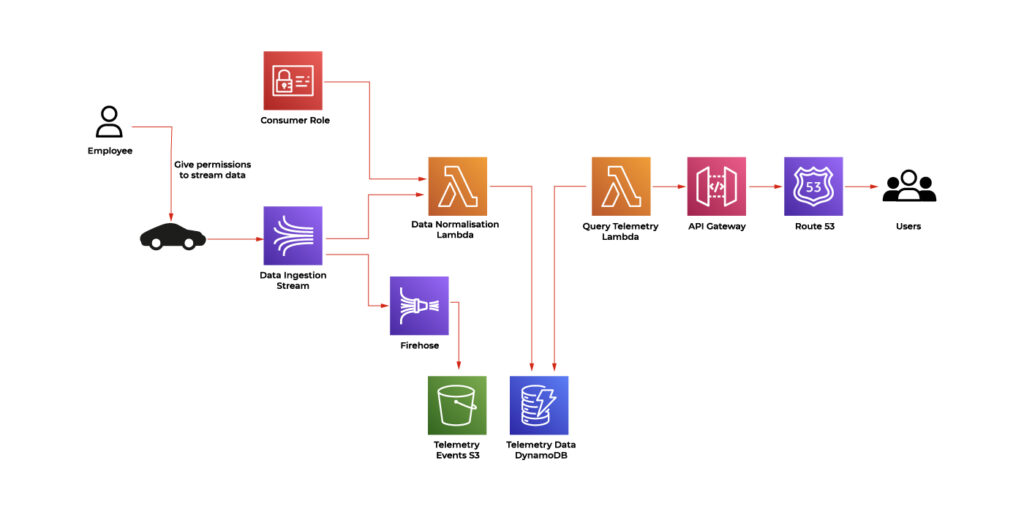
Conclusion
In the modern tech landscape, the quest for complete vehicle data is a paramount objective. Tech companies seek to collect critical information about the status of owned cars to enable proactive maintenance and rapid responses to a spectrum of incidents, from theft and damage to simple misplacement. This imperative relies on the remote monitoring of vehicles through the collection and storage of data on servers or in the cloud, offering the capability to monitor a vehicle's status from any corner of the globe. This is especially essential for companies like car rental firms and transportation services, with applications ranging from tracking stolen cars through GPS data to analyzing accident events and managing fuel or charging for rental vehicles.
The core of this mission is to strike a balance between data collection, security, and architectural planning. The process involves careful consideration of data collection methods, adherence to legal and security best practices, and informed choices for data storage solutions. The evolving landscape of vehicle data offers endless possibilities for tech companies to harness the power of telemetry and deliver an enhanced experience for their customers.

Quarkus framework overview and comparison with Spring Boot
In this article, we’ll give an overview of the Quarkus framework and compare it with Spring Boot - the most popular Java backend framework.
Quarkus is an open-source Java framework for developing web applications. It is designed to build apps in a modern approach with microservices and cloud-native applications. Quarkus has built-in support for the two most popular package managers: Gradle and Maven. By default, a new starter project created using the official Quarkus CLI uses Maven, although it may be easily switched to generate a grade-based project instead.
Features comparison to Spring Boot framework
Let’s make an overview of the main features available in Quarkus and compare them to the equivalent ones from Spring Framework.
Application configuration
Quarkus uses an open-source SmallRye Config library for configuring applications. By default, it uses application.properties files for this purpose. However, there is an option to also use the yaml file. In order to enable yaml configuration, we need to add a quarkus-config-yaml dependency. Quarkus may also additionally read configuration using environment variables specified in the .env file. This is particularly useful for local development.
You may store some local settings in the .env file e.g., to enable retrieval of credentials from external sources for local builds and not commit the file, keeping it for local usage only. Spring does not support reading environment variables from an .env file, so developers have to either inject them by IDE or configure them directly using the application configuration file.
Similarly to Spring, Quarkus supports different profiles depending on the target environment. This may be achieved by adding a profile name to the application.properties file name, e.g.:
application.properties – base configuration
application-dev.properties – extended configuration for the dev environment. When the dev profile is active, it will add (or override) the configuration to the base profile.
There is also an ability to build a configuration hierarchy with an additional configuration layer to mention base and profile-specific configuration. We may specify the name of the parent profile using quarkus.config.profile.parent in application-<profile>.properties file. E.g., by specifying quarkus.config.profile.parent=common in the application-dev.properties file, we’ll get a three-level hierarchy:
application.properties – base configuration application-common.properties – overrides/extends base configuration
application-dev.properties – overrides/extends common profile configuration
Spring has similar setting called spring.config.import which allows to import properties from a specified file rather than creating a hierarchy.
Dependency injection
Quarkus uses Jakarta EE Contexts and Dependency Injection engine. Similarly to Spring, Quarkus uses the concept of a bean. A bean is an object managed by an application environment (container) which creation and behavior can be controlled by the developer in a declarative style using annotations. For injecting beans, same as in the Spring Boot, we may use field, setter, and constructor injections.
Beans can be created by annotating the bean class with a scoped annotation:
@ApplicationScopedpublic class DataService {
public void writeData() {
//...
}
}
Compare with similar bean in Spring Boot:
@Servicepublic class DataService {
public void writeData() {
//...
}
}
Another way to define beans is to use producer methods or fields. This is similar to @Configuration classes in Spring Boot.
Quarkus:
// Define beans@ApplicationScopedpublic class SettingsProducer {
@Produces
String appToken = "123abc";
@Produces
    Map<String, String> settings() {
        return Map.of(
            "setting 1", "value1",
            "setting 2", "value2"
        );
    }
@Produces
    MyBean myBean() {
        return new MyBean(); // custom class
    }

}

// Inject beans:@ApplicationScopedpublic class DataService {
@Inject
private String appToken;
@Inject
private Map<String, String> settings;
@Inject
private MyBean myBean;
//…
}
Equivalent Spring Boot code:
// Configuration:@Configuration
public class SettingsProducer {
@Bean
    String appToken() {
        return "123abc";
    }
@Bean
    Map<String, String> settings() {
        return Map.of(
            "setting 1", "value1",
            "setting 2", "value2"
        );
    }
@Bean
    MyBean myBean() {
        return new MyBean();
    }
}

// Injecting beans:@Beanpublic class DataService {
@Autowired
private String appToken;
@Autowired
@Qualifier("settings") // needed to explicitly tell spring that Map itself is a bean
private Map<String, String> settings;
@Autowired
    private MyBean myBean;

    //…
}
Quarkus also provides built-in mechanisms for interceptors, decorator, and event handling using Jakarta EE framework annotations and classes.
RESTful API
Building RESTful services with Quarkus is enabled by RESTEasy Reactive framework, which is an implementation of Jakarta REST specification. The example class to handle endpoint requests:
@Path("/api")
public class DataResource {
@GET
    @Path("resource")
    public String getData() {
        return "My resource";
    }
@POST
    @Path("add/{data}")
public String addData(String data, @RestQuery String type) {
return "Adding data: " + data + " of type: " + type;
}
}
Class annotation @Path defines the root path of the URL. Each method contains HTTP method annotation ( @GET, @POST ) and @Path annotation that becomes a subpath of the root part. That is, in the example above, getData() is called for GET /api/resource request. Method addData() is called for POST /api/add/some_text?type=text request. Path component some_text will be specified as a data parameter to the addData() method. Query parameter text will be passed as a type parameter.
In Spring Boot, the above endpoint implementation using Spring Web is very similar:
@RestController
@RequestMapping("/api")
public class TestController {
@GetMapping("resource")
    public String hello() {
        return "My resource";
    }
@PostMapping("add/{data}")
public String addData(@PathVariable String data, @RequestParam String type) {
return "Adding data: " + data + " of type: " + type;
}
}
Security
Quarkus has its own Security framework, similarly to Spring Boot. Quarkus Security has built-in authentication mechanisms (like Basic, Form-based etc) and provides an ability to use well-known external mechanisms, such as OpenID Connect or WebAuth. It also contains security annotations for role-based access control. On the other hand, Spring Security has more abilities and is more flexible than Quarkus Security. E.g., @Secured and @PreAuthorize Spring annotations are not provided natively by Quarkus. However, Quarkus can be integrated with Spring Security to use the functionality that is provided by Spring Security only.
Cloud integration
Quarkus supports building container images when creating an application. The following container technologies are supported:
- Docker. To generate a Dockerfile that allows the building of a docker image, the quarkus-container-image-docker extension is used.
- Jib. The Jib container images can be built by using the quarkus-container-image-jib extension. For Jib containerization, Quarkus provides caching of the app dependencies stored in a layer different from the application. This allows to rebuild the application fast. It also makes the application build smaller when pushing the container. Moreover, it gives the ability to build apps and containers without the need to have any client-side docker-related tool in case only push to the docker registry is needed.
- OpenShift. To build an OpenShift container, the quarkus-container-image-openshift is needed. The container is built by only uploading an artifact and its dependencies to the cluster, where they are merged into the container. Building OpenShift builds requires the creation of BuildConfig and two ImageStream resources. One resource is required for the builder image and one for the output image. The objects are created by the Quarkus Kubernetes extension.
- Buildpack. Quarkus extension quarkus-container-image-buildpack uses build packs to create container images. Internally, the Docker service is used.
Quarkus is positioned as a Kubernetes native. It provides a Quarkus Kubernetes extension that allows the deployment of apps to Kubernetes. This simplifies workflow and, in simple applications, allows one to deploy to Kubernetes in one step without deep knowledge of Kubernetes API itself. Using quarkus-kubernetes dependency provides auto-generated Kubernetes manifest in the target directory. The manifest is ready to be applied to the cluster using the following example command:
kubectl apply -f target/kubernetes/kubernetes.json
Quarkus also creates a dockerfile for the docker image for deployment. Application properties of the Quarkus app allow the configuration of container images to set their names, groups, etc. Kubernetes-related application properties allow the setup of a generated resource. E.g, quarkus.kubernetes.deployment-kind sets the resource kind to, e.g., Deployment, StatefulSet, or Job.
When it comes to Spring Boot it also has support of containerization and Kubernetes. However, such support is not out-of-the-box. The setup and deployment require much more configuration and technology-specific knowledge comparing to how it’s implemented in Quarkus. Quarkus reduces boilerplate code and setup since it has a native configuration for Kubernetes and containerization.
Production readiness and technical support
Quarkus is a relatively new framework comparing to Spring/Spring Boot. The initial Quarkus release took place on May 20, 2019. The first production Spring Framework release was on March 24, 2004, and Spring Boot was first released on April 1, 2014. Quarkus releases new versions a bit more frequently than Spring Boot, although the frequency is very good for both frameworks. There are 3-4 Quarkus releases per month and 5-6 releases of Spring Boot.
When it comes to bugs, there are 8289 total issues marked as bugs on github for Quarkus, and only 881 of them are in opened state. For Spring Boot, there are 3473 total issues that are marked as bugs, and only 66 of them are opened. The bugs are fixed faster for Spring Boot. The reason may be because it has a larger supporting community as Spring is much older.
Spring Boot has long-term support (LTS) versions that are maintained (updates/bug fixes) for a longer period of time without introducing major changes. Such an approach gives more stability and allows the use of the older version of your application that is getting all the critical fixes (e.g., fixes of known vulnerabilities). At the same time, you may work on the newer releases of your product to integrate and test the latest version of the framework. Spring Boot offers one year of regular support for each LTS edition and more than two years of commercial support.
Quarkus recently introduced LTS versions supported for one year. They plan to release a new LTS version every six months. Currently, Quarkus does not have commercial support for LTS versions.
Summary
In this article, we described key features of the Quarkus framework and compared them with the equivalent features in Spring Boot. Let’s summarize the main pros and cons of both frameworks in every area addressed.
- Application Configuration
Both Spring Boot and Quarkus have well-developed systems of configuration management. Even though Quarkus has the ability to build a simple three-level hierarchy of profiles, both frameworks can handle app configuration at a good level to satisfy app development needs.
- Dependency Injection
Both frameworks use a similar approach with beans injected at run time and use annotations to define bean types, assign bean information, and specify injection points.
- RESTful API
Spring Boot and Quarkus have very similar approach to writing RESTful API, with no major differences.
- Security
Quarkus provides the same authorization methods as Spring and has built-in integration with well-known authentication mechanisms. Spring Security offers more security-related annotations, although some of them can be used in Quarkus as it has the ability to integrate with the Spring Security framework.
- Cloud integration
Quarkus has native support for containerization and Kubernetes. It provides more abilities and is easier to use in cloud-native environments and tools compared to Spring Boot. This may be a key factor in choosing between Spring Boot and Quarkus for a development of a new app designed for a cloud-native environment.
- Production Readiness and Technical Support
Spring Boot is a much older framework. It has a larger support community and more users. It provides more robust LTS versions with the ability to extend tech support even more with LTS commercial support. Quarkus, on the other hand, has just recently introduced LTS versions with a shorter support period and doesn’t have commercial options. However, both frameworks are stable, bugs are continuously fixed, and new versions are released frequently.
For the most of its features, Quarkus implements Jakarta EE specifications, while Spring Boot includes its own solutions. Implementing the specification offers the advantage of creating a more consistent and robust API, as opposed to using non-standard methods. On the other hand, Spring Boot is quite an old and well-known framework and its features have proven to be stable and robust over time.

Android Automotive OS 11 Camera2 and EVS - Two different camera subsystems up and running
Android Automotive OS, AAOS in short, is a vehicle infotainment operating system that has gained a lot of traction recently, with most of the OEMs around the world openly announcing new versions of their infotainment based on Android. AAOS is based on the AOSP (Android Open Source Project) source code, which makes it fully compatible with Android, with additions that make it more useful in cars – different UI, integration with hardware layer, or vehicle-specific apps.
For OEMs and Tier1s, who are deeply accustomed to infotainment based on QNX/Autosar/Docker/Linux, and software developers working on AAOS apps, it’s sometimes difficult to quickly spin-up the development board or emulator supporting external hardware that has no out-of-the-box emulation built by Google. One of the common examples is camera access, which is missing in the official AAOS emulator these days, but the hardware itself is quite common in modern vehicles – which makes implementation of applications similar to Zoom or MS Teams for AAOS tempting to app developers.
In this article, I will explain how to build a simple test bench based on a cost-effective Raspberry Pi board and AAOS for developers to test their camera application. Examples will be based on AAOS 11 running on Raspberry Pi 4 and our Grape Up repository. Please check our previous article: " Build and Run Android Automotive OS on Raspberry Pi 4B " for a detailed description of how to run AAOS on this board.
Android Automotive OS has 2 different subsystems to access platform cameras: Camera2 and EVS. In this article, I will explain both how we can use it and how to get it running on Android Automotive OS 11.
Exterior View System (EVS)
EVS is a subsystem to display parking and maneuvering camera image. It supports multiple cameras' access and view. The main goal and advantage of that subsystem is that it boots quickly and should display a parking view before 2 seconds, which is required by law.
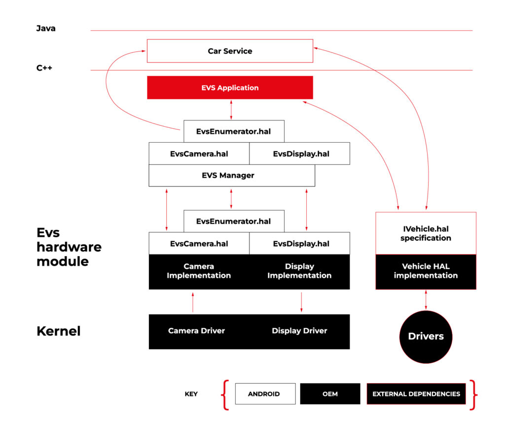
Source https://source.android.com/docs/automotive/camera-hal
As you can see on the attached diagram, low layers of EVS depend on OEM source code. OEM needs to deliver Camera and Display implementation. However, Android delivers a sample application (/hardware/interfaces/automotive/evs/1.0) , which uses Linux V4L2 and OpenGL to grab camera frames and display them. You can find more information about EVS at https://source.android.com/docs/automotive/camera-hal
In our example, we will use samples from Android. Additionally, I assume you build our Raspberry Pi image (see our article ), as it has multiple changes that allow AAOS to reliably run on RPi4 and support its hardware.
You should have a camera connected to your board via USB. Please check if your camera is detected by V4L2. There should be a device file:
/dev/video0
Then, type on the console:
su

setprop persist.automotive.evs.mode 1
This will start the EVS system.
To display camera views:
evs_app
Type Ctrl-C to exit the app and go back to the normal Android view.
Camera2
Camera2 is a subsystem intended for camera access by “normal” Android applications (smartphones, tablets, etc.). It is a common system for all Android applications, recently slowly being replaced by CameraX. The developer of an Android app uses Java camera API to gain access to the camera.
Camera2 has three main layers, which are shown in the diagram below:
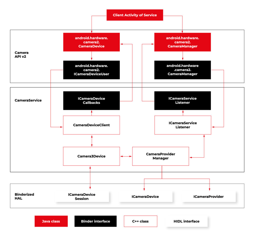
Source https://source.android.com/docs/core/camera
Low-level Camera access is implemented in CameraProvider. OEM can implement their own provider or a V4L2 camera driver can be used.
To get Camera2, you should enable it in the Car product make file. In
packages/services/Car/car_product/build/car_base.mk change config.disable_cameraservice to false.
PRODUCT_PROPERTY_OVERRIDES += config.disable_cameraservice=false
After that, rebuild Android:
make ramdisk systemimage vendorimage
Put it in the SD card and boot RPi with it. You will be able to run the “Camera” application on the AAOS screen, see camera output from the connected webcam, and run and debug applications using Camera API.
Summary
Now you know how to run both AAOS camera APIs on the RPi4 board. You can use both APIs to develop automotive applications leveraging cameras and test them using a simple USB webcam, which you may have somewhere on the shelf. If you found this article useful, you can also look at our previous articles about AAOS – both from the application development perspective and the OS perspective . Happy coding!
Unveiling the EU Data Act: Automotive industry implications
Fasten your seatbelts! The EU Data Act aims to drive a paradigm shift in the digital economy, and the automotive industry is about to experience a high-octane transformation. Get ready to explore the user-centric approach , new data-sharing mechanisms, and the roadmap for OEMs to adapt and thrive in the European data market. Are you prepared for this journey?
Key takeaways
- The EU Data Act grants users ownership and control of their data while introducing obligations for automotive OEMs to ensure fair competition.
- The Act facilitates data sharing between users, enterprises, and public sector bodies to promote innovation in the European automotive industry.
- Automotive OEMs must invest in resources and technologies to comply with the EU Data Act regulations for optimal growth opportunities.
The EU Data Act and its impact on the automotive industry
The EU Data Act applies to manufacturers, suppliers, and users of products or services placed on the market in the EU, as well as data holders and recipients based in the EU.
What is the EU Data Act regulation?
The EU Data Act is a proposed regulation that seeks to harmonize rules on fair access to and use of data in the European Union. The regulation sets out clear guidelines on who is obliged to surrender data, who can access it, how it can be used, and for what specific purposes it can be utilized.
In June 2023, the European Union took a significant step towards finalizing the Data Act, marking a pivotal moment in data governance. While the Act awaits formal adoption by the Council and Parliament following a legal-linguistic revision, the recent informal political agreement suggests its inevitability. This groundbreaking regulation will accelerate the monetization of industrial data while ensuring a harmonized playing field across the European Union.
User-centric approach
The European Data Act is revving up the engines of change in the automotive sector, putting users in the driver’s seat of their data and imposing specific obligations on OEMs. This means that connected products and related services must provide users with direct access to data generated in-vehicle, without any additional costs, and in a secure, structured, and machine-readable format.
Data handling by OEMs
A significant change is about to happen in data practices, particularly for OEMs operating in the automotive industry. Manufacturers and designers of smart products, such as smart cars, will be required to share data with users and authorized third parties. This shared data includes a wide range of information:
Included in the Sharing Obligation: The data collected during the user's interaction with the smart car that includes information about the car's operation and environment. This information is gathered from onboard applications such as GPS and sensor images, hardware status indications, as well as data generated during times of inaction by the user, such as when the car is on standby or switched off. Both raw and pre-processed data are collected and analyzed.
Excluded from the Sharing Obligation: Insights derived from raw data, any data produced when the user engages in activities like content recording or transmitting, and any data from products designed to be non-retrievable are not shared.
Sharing mechanisms and interactions
Data holders must make vehicle-generated data available (including associated metadata) promptly, without charge, and in a structured, commonly used, machine-readable format.
The legal basis for sharing personal data with connected vehicle users and legal entities or data recipients other than the user varies depending on the data subject and the sector-specific legislation to be presented.
Data access and third-party services
The Data Act identifies eligible entities for data sharing, encompassing both physical persons, such as individual vehicle owners or lessees, and legal persons, like organizations operating fleets of vehicles.
Requesting data sharing
Data can be accessed by users who are recipients either directly from the device's storage or from a remote server that captures the data. In cases where the data cannot be accessed directly, the manufacturers must promptly provide it.
The data must be free, straightforward, secure, and formatted for machine readability, and its quality should be maintained where necessary. There may be contracts that limit or deny access or further distribution of data if it breaches legal security requirements. This is a critical aspect for smart cars where sharing data might pose a risk to personal safety.
If the recipient of data is a third party , they cannot use the data to create competing products, only for maintenance. They cannot share the data unless it is for providing a user service and cannot prevent users who are consumers from sharing it with other parties.
Fair competition and trade secrets
The Data Act mandates that manufacturers share data, even when it is protected by trade secret laws. However, safeguards exist, allowing OEMs to impose confidentiality obligations and withhold data sharing in specific circumstances. These provisions ensure a balance between data access and trade secret protection. During the final negotiations on the Data Act, safeguarding trade secrets was a primary focus.
The Data Act now has provisions to prevent potential abusive behavior by data holders. It also includes an exception to data-sharing that permits manufacturers to reject certain data access requests if they can prove that such access would result in the disclosure of trade secrets, leading to severe and irreversible economic losses.
Connected vehicle data
Connected vehicle data takes the spotlight under the EU Data Act, empowering users with real-time access to their data and enabling data sharing with repair or service providers.
The implementation of the Data Act heavily involves connected cars. As per the Act, users, including companies, have the right to access the data collected by vehicles. However, manufacturers have the option to limit access under exceptional circumstances. This has a significant impact on data collection practices in the automotive sector.
Preparing for the EU Data Act: A guide for automotive OEMs
To stay ahead of the curve, OEMs must understand the business implications of the Data Act, adapt to new regulations, and invest in the necessary resources and technologies to ensure compliance.
As connected vehicles become the norm, OEMs that embrace the Data Act will be well-positioned to capitalize on new opportunities and drive growth in the European automotive sector.
Business implications
The EU Data Act imposes significant business implications on automotive OEMs, necessitating changes in their data handling practices and adherence to new obligations. As the industry embraces the user-centric approach to data handling, OEMs must design connected products and related services that provide users with access to their in-vehicle data.
To ensure a smooth transition and maintain a competitive edge, automotive OEMs must undertake a tailored and strategic preparation process.
Adapting to new regulations
Failure to comply with the Data Act could result in legal and financial repercussions for automotive OEMs. In order to avoid any possible problems, they should invest in the necessary resources and technologies to ensure compliance with the regulations of the Data Act.
They should also engage proactively with the requirements of the Data Act and implement compliance measures strategically.
By taking the following steps, automotive OEMs can navigate the regulatory landscape effectively and seize growth opportunities in the European automotive sector:
In-Depth Knowledge: Dive deep into the EU Data Act, with a special focus on its impact on the automotive industry. Recognize that the automotive sector is central to this regulation, requiring industry-specific understanding.
Data Segmentation: Perform a comprehensive analysis of your data, categorizing it into distinct groups. Identify which data types fall within the purview of the EU Data Act.
Compliance Framework Development:
- Internal Compliance: Audit and update policies to comply with the EU Data Act. Develop a data governance framework for access, sharing, and privacy.
- Data Access Protocols: Establish unambiguous protocols for data access and sharing, including procedures for obtaining user consent, data retrieval, and sharing modalities.
Data Privacy and Security:
- Data Safeguards: Enhance data privacy and security, including encryption and access controls.
Data Utilization: Develop plans for leveraging this data to generate new revenue streams while adhering to the EU Data Act's mandates.
User Engagement and Consent:
- Transparency: Forge clear and transparent channels of communication with users. Keep users informed about data collection, sharing, and usage practices, and obtain well-informed consent.
- Consent Management: Implement robust consent management systems to efficiently monitor and administer user consent. Ensure that users maintain control over their data.
Legal Advisors: Engage legal experts well-versed in data protection and privacy laws, particularly those relevant to the automotive sector. Seek guidance for interpreting and implementing the EU Data Act within your specific industry context.
Data Access Enhancement: Invest in technology infrastructure to facilitate data access and sharing as per the EU Data Act's stipulations. Ensure that data can be easily and securely provided in the required format.
Employee Education: Educate your workforce on the intricacies of the EU Data Act and its implications for daily operations. Ensure that employees possess a strong understanding of data protection principles.
Ongoing Compliance Oversight: Establish mechanisms for continuous compliance monitoring. Regularly assess data practices, consent management systems, and data security protocols to identify and address compliance gaps.
Collaboration with Peers: Collaborate closely with industry associations, fellow automotive OEMs, and stakeholders to share insights, best practices, and strategies for addressing the specific challenges posed by the EU Data Act in the automotive sector.
Future-Ready Solutions: Develop adaptable and scalable solutions that accommodate potential regulatory landscape shifts. Remain agile and prepared to adjust strategies as needed.
Boosting innovation capabilities
The Data Act may bring some challenges, but it also creates a favorable environment for innovation. By making industrial data more accessible, the Act offers a huge potential for data-driven businesses to explore innovative business models. Adapting to the Act can improve a company's ability to innovate, allowing it to use data as a strategic asset for growth and differentiation.
Summary
The EU Data Act is driving a paradigm shift in the automotive sector, putting users in control of their data and revolutionizing the way OEMs handle, share, and access vehicle-generated data.
By embracing the user-centric approach, ensuring compliance with data sharing and processing provisions, and investing in innovation capabilities, data holders can unlock new opportunities and drive growth in the European automotive market.
It's time for OEMs to take actionable steps to comply with the new regulation . Read this guide on building EU Data Act-compliant connected car software to learn what they are.
Get prepared to meet the EU Data Act deadlines
Ready to turn compliance into a competitive advantage? We’re here to assist you , whether you need expert guidance on regulatory changes or customized data-sharing solutions.