How to manage fire trucks – IoT architecture with isolated applications and centralized management system


Welcome to a short cycle of articles that shows a way to combine network techniques and AWS services for a mission-critical automotive system .
We’ll show you how to design and implement an IoT system with a complex edge architecture.
The cycle consists of three articles and shows the architecture design, a step-by-step implementation guide, and some pitfalls with the way to overcome these.
Let’s start!
AWS IoT usage to manage vehicle fleet
Let’s create an application. But this won’t be a typical, yet another CRUD-based e-commerce system. This time, we’d like to build an IoT-based fleet-wise system with distributed (on-edge/in-cloud) computing.
Our customer is an automotive company that produces fire trucks. We’re not interested in engine power, mechanical systems, and firefighters' equipment. We’re hired to manage the fleet of vehicles for both the producer and its customers.
Each truck is controlled by a central, “rule-them-all” computer connected to all vehicles CAN buses, and whole extra firefighters’ equipment. The computer sends basic vehicle data (fuel level, tire pressure, etc.) to the fire station and a central emergency service supervisor. It receives new orders, calculates the best route to targets and controls all the vehicle equipment - pumps, lights, signals, and of course – the ladder. Also, it sends some telemetry and usage statistics to the producer to help design even better trucks in the future.
However, those trucks are not the same. For instance, in certain regions, the cabin must be airtight, so extra sensors are used. Some cities integrate emergency vehicles with city traffic light systems to clear the route for a running truck. Some stations require specialized equipment like winches, extra lights, power generators, crew management systems, etc.
Moreover, we need to consider that those trucks often operate in unpleasant conditions, with a limited and unreliable Internet connection available.
Of course, the customer would like to have a cloud-based server to manage everything both for the producer and end users - to collect logs and metrics with low latency, to send commands with no delay, and with a colorful, web-based, easy-to-use GUI.
Does it sound challenging? Let's break it down!
Requirements
Based on a half-an-hour session with the customer, we've collected the following, a bit chaotic, set of business requirements:
- a star-like topology system, with a cloud in the center and trucks around it,
- groups of trucks are owned by customers - legal entities that should have access only to their trucks,
- each group that belongs to a customer may be customized by adding extra components, both hardware-, or software-based,
- each truck is controlled by identical, custom, Linux-based computers running multiple applications provided by the customer or third parties,
- truck-controlling computers are small, ARM-based machines with limited hardware and direct Internet access via GSM,
- Internet connection is usually limited, expensive, and non-reliable,
- the main computer should host common services, like GPS or time service,
- some applications are built of multiple components (software and hardware-based) - hardware components communicate with the main computers via the in-vehicle IP network,
- the applications must communicate with their servers over the Internet, and we need to control (filter/whitelist) this traffic,
- each main computer is a router for the vehicle network,
- each application should be isolated to minimize a potential attack scope,
- components in trucks may be updated by adding new software or hardware components, even after leaving the production line,
- the cloud application should be easy - read-only dashboards, truck data dump, send order, both-way emergency messages broadcast,
- new trucks can be added to the system every day,
- class-leading security is required - user and privileges management, encrypted and signed communication, operations tracking, etc.
- provisioning new vehicles to the system should be as simple as possible to enable the factory workers to do it.
As we’ve learned so far, the basic architecture is as shown in the diagram below.
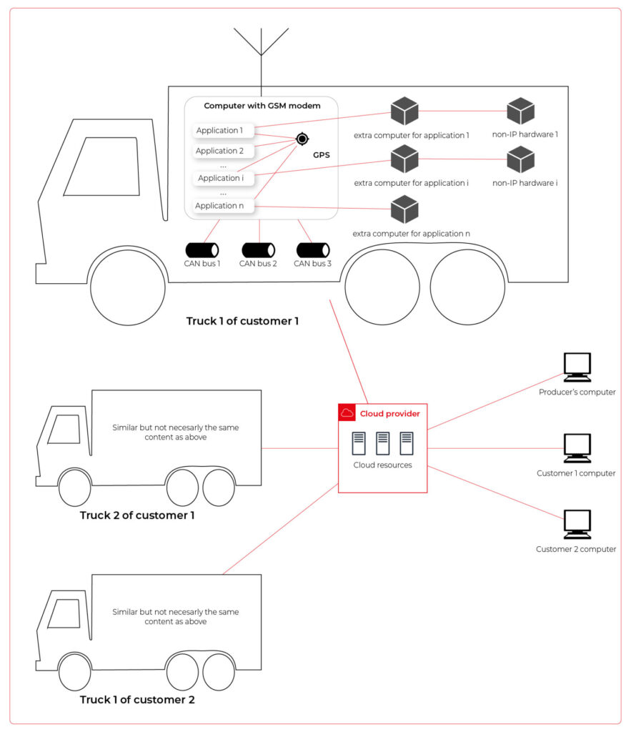
Our job is to propose a detailed architecture and prove the concept. Then, we’ll need a GPT-based instrument bench of developers to hammer it down.
The proposed architecture
There are two obvious parts of the architecture - the cloud one and the truck one. The cloud one is easy and mostly out-of-scope for the article. We need some frontend, some backend, and some database (well, as usual). In the trucks, we need to separate applications working on the same machine and then isolate traffic for each application. It sounds like containers and virtual networks. Before diving into each part, we need to solve the main issue - how to communicate between trucks and the cloud.
Selecting the technology
The star-like architecture of the system seems to be a very typical one - there is a server in the center with multiple clients using its services. However, in this situation, we can't distinguish between resources/services supplier (the server) and resources/services consumers (the clients). Instead, we need to consider the system as a complex, distributed structure with multiple working nodes, central management, and 3rd party integration. Due to the isolation, trucks’ main computers should containerize running applications. We could use Kubernetes clusters in trucks and another one in the cloud, but in that case, we need to implement everything manually – new truck onboarding, management at scale, resource limiting for applications, secured communication channels, and OTA updates. In the cloud, we would need to manage the cluster and pods, running even when there is no traffic.
An alternative way is the IoT. Well, as revealed in the title, this is the way that we have chosen. IoT provides a lot of services out-of-the-box - the communication channel, permissions management, OTA updates, components management, logs, metrics, and much more. Therefore, the main argument for using it was speeding up the deployment process.
However, we need to keep in mind that IoT architecture is not designed to be used with complex edge devices. This is our challenge, but fortunately, we are happy to solve it.
Selecting the cloud provider
The customer would like to use a leading provider, which reduces the choice to the top three in the World: AWS, MS Azure, and GCP.
The GCP IoT Core is the least advanced solution. It misses a lot of concepts and services available in the competitors, like a digital twin creation mechanism, complex permissions management, security evaluation, or a complex provisioning mechanism.
The Azure IoT is much more complex and powerful. On the other hand, it suffers from shortcomings in documentation, and - what is most important - some features are restricted to Microsoft instruments only (C#, Visual Studio, or PowerShell). On the other hand, it provides seamless AI tool integration, but it’s not our case for now.
But the last one – AWS IoT – fits all requirements and provides all the services needed. Two MQTT brokers are available, plenty of useful components (logs forwarding, direct tunnel for SSH access, complex permission management), and almost no limitation for IoT Core client devices. There is much more from AWS Greengrass - an extended version with higher requirements (vanilla C is not enough), but we can easily fulfill those requirements with our ARM-based trucks’ computers.
The basic architecture
Going back to the start-like topology, the most important part is the communication between multiple edge devices and the core. AWS IoT provides MQTT to enable a TCP-based, failure-resistant communication channel with a buffer that seamlessly keeps the communication on connection lost. The concept offers two MQTT brokers (in the cloud and on the edge) connected via a secured bridge. This way, we can use the MQTT as the main communication mechanism on the edge and decide which topics should be bridged and transferred to the cloud. We can also manage permissions for each topic on both sides as needed.
The cloud part is easy – we can synchronize the IoT MQTT broker with another messaging system (SNS/SQS, Kafka, whatever you like) or read/write it directly from our applications.
The edge part is much more complex. In the beginning, let’s assume that there are two applications running as executable programs on the edge. Each of these uses its own certificate to connect to the edge broker so we can distinguish between them and manage their permissions. It brings up some basic questions – how to provide certificates and ensure that one application won’t steal credentials from another. Fortunately, AWS IoT Greengrass supplies a way to run components as docker containers – it creates and provides certificates and uses IPC (inter-process communication) to allow containers to use the broker. Docker ensures isolation with low overhead, so each application is not aware of the other one. See the official documentation for details: Run a Docker container - AWS IoT Greengrass (amazon.com) .
Please note the only requirement for the applications, which is, in fact, the requirement we make to applications’ providers: we need docker images with applications that use AWS IoT SDK for communication.
See the initial architecture in the picture below.
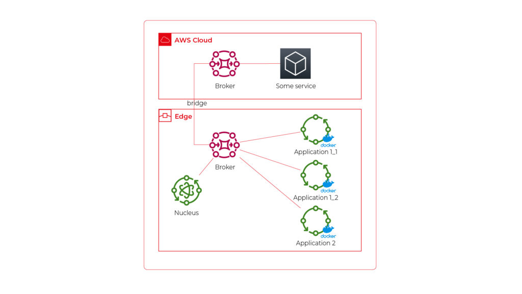
As you can see, Application 1 contains two programs (separate docker containers) communicating with each other via the broker: Application 1_1 and Application 1_2. Thanks to the privileges management, we are sure that Application 2 can’t impact or read this communication. If required, we can also configure a common topic accessible by both applications.
Please also note that there is one more component – Nucleus. You can consider it as an orchestrator required by AWS IoT to rule the system.
Of course, we can connect thousands of similar edges to the same cloud, but we are not going to show it on pictures for readability reasons. AWS IoT provides deployment groups with versioning for OTA updates based on typical AWS SDK. Therefore, we can expose a user-friendly management system (for our client and end users) to manage applications running on edge at scale.
Virtual networks
Now, let’s challenge the architecture with a more complex scenario. Let’s assume that Application 2 communicates with an in-cabin air quality sensor – a separate computer that is in the same IP network. We can assume the sensor is a part of Application 2, and our aim is to enable such communication but also to hide it from Application 1. Let’s add some VLANs and utilize network interfaces.
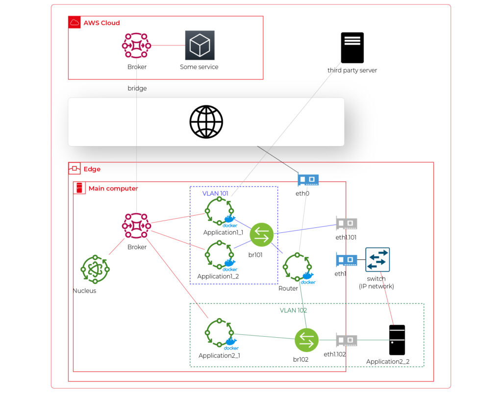
Starting from the physical infrastructure, the main computer uses two interfaces – eth0 to connect to the Internet and eth1 connected to a physical, managed switch (the “in-vehicle IP network” mentioned above). The Application 2_2 computer (the air quality sensor) is connected to the switch to a port tagged as VLAN 102, and the switch is connected to eth1 via a trunk port.
The eth0 interface is used by the main computer (host) to communicate with the Internet, so the main MQTT bridging is realized via this interface. On the other hand, there is also a new Greengrass-docker component called router. It’s connected to eth0 and to two virtual bridges – br101 and br102. Those bridges are not the same as the MQTT bridge. This time, we need to use the kernel-based Linux feature “bridge,” which is a logical, virtual network hub. Those bridges are connected to virtual network interfaces eth1.101 and eth1.102 and to applications’ containers.
This way, Application 1 uses its own VLAN 101 (100% virtual), and Application 2 uses its own VLAN 102 (holding both virtual and physical nodes). The application separation is still ensured, and there is no logical difference between virtual and mixed VLANs. Applications running inside VLANs can’t distinguish between physical and virtual nodes, and all IP network features (like UDP broadcasting and multicasting) are allowed. Note that nodes belonging to the same application can communicate omitting the MQTT (which is fine because the MQTT may be a bottleneck for the system).
Moreover, there is a single security-configuration point for all applications. The router container is the main gateway for all virtual and physical application-nodes, so we can configure a firewall on it or enable restricted routes between specific nodes between applications if needed. This way, we can enable applications to communicate with third-party servers over the Internet (see Application 1_1 in the picture), to communicate with individual nodes of the applications without restrictions, and to control the entire application-related traffic in a single place. And this place – the router – is just another Greengrass component, ready to be redeployed as a part of the OTA update. Also, the router is a good candidate to serve traffic targeting all networks (and all applications), e.g., to broadcast GPS position via UDP or to act as the network time server.
One more broker
What if… the application is provided as a physical machine only?
Well, as the main communication channel is MQTT, and the direct edge-to-Internet connection is available but limited, we would like to enable a physical application to use the MQTT. MQTT is a general standard for many integrated systems (small computers with limited purposes), but our edge MQTT broker is AWS-protected, so there are two options available. We can force the application supplier to be AWS-Greengrass compatible, or we need another broker. As we’re pacifists and we can’t stand forcing anybody to do anything, let’s add one more broker and one more bridge.
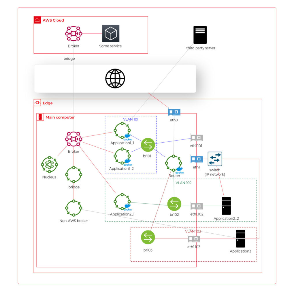
This time, there are two new components. The first one, an MQTT broker (Mosquitto or similar), interacts with Application 3. As we can’t configure the Mosquitto to act as a bridge for the AWS-managed broker, there is one more, custom application running on the server for this purpose only – a Greengrass component called “bridge”. This application connects to both local MQTT brokers and routes specific messages between them, as configured. Please note that Application 3 is connected to its own VLAN even if there are no virtual nodes. The reason is – there are no virtual nodes yet, but we’d like to keep the system future-proof and consistent. This way, we keep the virtual router as a network gateway for Application 3, too. Nevertheless, the non-AWS broker can listen to specific virtual interfaces, including eth1.103 in this case, so we can enable it for specific VLANs (application) if needed.
Summary
The article shows how to combine AWS IoT, docker, and virtual networks to achieve a future-proof fleet management system with hardware- and software-based applications at scale. We can use AWS tools to deliver new applications to edge devices and manage groups evoking truck owners or truck models. Each vehicle can be equipped with an ARM computer that uses AWS-native fleet provisioning on OS initialization to join the system. The proposed structure may seem to be complex, but you need to configure it only once to fulfill all requirements specified by the client.
However, theory is sometimes easier than practice, so we encourage you to read the following article with implementation details .

Data powertrain in automotive: Complete end-to-end solution
We power your entire data journey, from signals to solutions
Check related articles
Read our blog and stay informed about the industry's latest trends and solutions.
Vehicle fleet as IoT – virtual networks on edge
In the earlier article , we’ve covered the detailed architecture of a fleet management system based on AWS IoT and on-edge virtual networks. Now, we can dive into implementation. Let’s create a prototype of an edge network with two applications running together on both virtual and physical nodes and with isolated virtual networks. As we don’t have fire trucks on hand, we use three computers (the main truck ARM computer simulated by a Raspberry Pi and two application nodes running on laptops) and a managed switch to connect them together.
Overview of topics and definitions used in the material
In this chapter, we provide concise explanations of key networking concepts and technologies relevant to the architecture discussed earlier. These definitions will help readers better understand the underlying mechanisms that enable efficient and flexible communication between Docker containers, the host system, and external devices. Familiarizing yourself with these concepts will facilitate a deeper understanding of the networking aspects of the presented system and their interrelationships.
- Docker Networking : a system that enables containers to communicate with each other and external networks. It provides various network drivers and options to support different network architectures and requirements, including bridge, host, overlay, and IPvlan/MACvlan drivers. Docker networking creates virtual networks and attaches containers to these networks. Each network has a unique IP address range, and containers within a network can communicate using their assigned IP addresses. Docker uses network drivers to manage container connectivity and network isolation.
- IPvlan : a Docker network driver that enables efficient container-to-container and container-to-external network communication by sharing the parent interface's MAC address with its child interfaces. In the context of the router Docker image in the presented topic, IPvlan provides efficient routing between multiple networks and reduces the management overhead associated with MAC addresses.
- Docker Bridge : a virtual network device that connects multiple Docker container networks, allowing containers to communicate with each other and the host system. By default, Docker creates a bridged network named "docker0" for containers to use. Users can create custom bridge networks to segment and isolate container traffic.
- Linux Bridge : a kernel-based network device that forwards traffic between network segments. It operates at the data link layer, similar to how ethernet frames function within the TCP/IP model. Linux Bridges are essential in creating virtual network interfaces for entities such as virtual machines and containers.
- veth : (Virtual Ethernet) a Linux kernel network device that creates a pair of connected virtual network interfaces. Docker uses veths to connect containers to their respective networks, with one end attached to the container and the other end attached to the network's bridge. In a bridged Docker network, veth pairs are created and named when a container is connected to a Docker bridge network, with one end of the veth pair being assigned a unique identifier within the container's network namespace and the other end being assigned a unique identifier in the host's network namespace. The veth pair allows seamless communication between the container and the bridge network. In simple words – veth is a virtual cable between (virtual or not) interfaces of the same machine.
- Network namespace : Docker provides containers with isolated network stacks, ensuring each container has its own private IPs and ports. VLANs (Virtual Local Area Networks) operate at the data link layer, allowing for the creation of logically segmented networks within a physical network for improved security and manageability. When combined in Docker, containers can be attached directly to specific VLANs, marrying Layer 2 (VLAN) and Layer 3 (namespaces) isolation.
- VLAN (Virtual Local Area Network) : a logical network segment created by grouping physical network devices or interfaces. VLANs allow for traffic isolation and efficient use of network resources by separating broadcast domains.
- iptable : a Linux command-line utility for managing packet filtering and network address translation (NAT) rules in the kernel's network filter framework. It provides various mechanisms to inspect, modify, and take actions on packets traversing the network stack.
- masquerade : a NAT technique used in iptables to mask the source IP address of outgoing packets with the IP address of the network interface through which the packets are being sent. This enables multiple devices or containers behind the masquerading device to share a single public IP address for communication with external networks. In the context of the presented topic, masquerading can be used to allow Docker containers to access the Internet through the router Docker image.
Solution proposal with description and steps to reproduce
Architecture overview

The architecture described consists of a Router Docker container, two applications’ containers (Container1 and Container2), a host machine, and two VLANs connected to a switch with two physical devices. The following is a detailed description of the components and their interactions.
Router Docker container
The container has three interfaces:
- eth0 (10.0.1.3): Connected to the br0net Docker network (10.0.1.0/24).
- eth1 (192.168.50.2): Connected to the home router and the internet, with the gateway set to 192.168.50.1.
- eth2 (10.0.2.3): Connected to the br1net Docker network (10.0.2.0/24).
Docker containers
Container1 (Alpine) is part of the br0net (10.0.1.0/24) network, connected to the bridge br0 (10.0.1.2).
Container2 (Alpine) is part of the br1net (10.0.2.0/24) network, connected to the bridge br1 (10.0.2.2).
Main edge device – Raspberry Pi or a firetruck main computer
The machine hosts the entire setup, including the router Docker image and the Docker containers (Container1 and Container2). It has two bridges created: br0 (10.0.1.2) and br1 (10.0.2.2), which are connected to their respective Docker networks (br0net and br1net)
VLANs and switch
The machine’s bridges are connected to two VLANs: enp2s0.1 (10.0.1.1) and enp2s0.2 (10.0.2.1). The enp2s0 interface is configured as a trunk connection to a switch, allowing it to carry traffic for multiple VLANs simultaneously.
Two devices are connected to the switch, with Device1 having an IP address of 10.0.1.5 and Device2 having an IP address of 10.0.2.5
DHCP Server and Client
Custom DHCP is required because of the IP assignment for Docker containers. Since we would like to maintain consistent addressing between both physical and virtual nodes in each VLAN, we let DHCP handle physical nodes in the usual way and assign addresses to virtual nodes (containers) by querying the DHCP server and assigning addresses manually to bypass the Docker addressing mechanism.
In short - the presented architecture describes a way to solve the non-trivial problem of isolating Docker containers inside the edge device architecture. The main element responsible for implementing the assumptions is the Router Docker container, which is responsible for managing traffic inside the system. The Router isolates network traffic between Container1 and Container2 containers using completely separate and independent network interfaces.
The aforementioned interfaces are spliced to VLANs via bridges, thus realizing the required isolation assumptions. The virtual interfaces on the host side are already responsible for exposing externally only those Docker containers that are within the specific VLANs. The solution to the IP addressing problem for Docker containers is also worth noting. The expected result is to obtain a form of IP addressing that will allow a permanent address assignment for existing containers while retaining the possibility of dynamic addressing for new components.
The architecture can be successfully used to create an end-to-end solution for edge devices while meeting strict security requirements.
Step-by-step setup
Now we start the implementation!
VLANs [execute on host]
Let’s set up VLANs.
enp2s0.1
auto enp2s0.1
iface enp2s0.1 inet static
address 10.0.1.1
network 10.0.1.0
netmask 255.255.255.0
broadcast 10.0.1.255

enp2s0.2
auto enp2s0.2
iface enp2s0.2 inet static
address 10.0.2.1
network 10.0.2.0
netmask 255.255.255.0
broadcast 10.0.2.255
Bridges [execute on host]
We should start by installing bridge-utils, a very useful tool for bridge setup.
sudo apt install bridge-utils
Now, let’s config the bridges.
sudo brctl addbr br0
sudo ip addr add 10.0.1.1/24 dev br0
sudo brctl addif br0 enp2s0
sudo ip link set br0 up

sudo brctl addbr br1
sudo ip addr add 10.0.2.1/24 dev br0
sudo brctl addif br0 enp2s0
sudo ip link set br0 up
Those commands create virtual brX interfaces, set IP addresses, and assign physical interfaces. This way, we bridge physical interfaces with virtual ones that we will create soon – it’s like a real bridge, connected to only one river bank so far.
Docker networks [execute on host]
Network for WLAN interface.
docker network create -d ipvlan --subnet=192.168.50.0/24 --gateway=192.168.50.1 -o ipvlan_mode=l2 -o parent=wlp3s0f0 wlan
Network for bridge interface br0.
docker network create --driver=bridge --subnet=10.0.1.0/24 --gateway=10.0.1.2 --opt "com.docker.network.bridge.name=br0" br0net
Network for bridge interface br1.
docker network create --driver=bridge --subnet=10.0.2.0/24 --gateway=10.0.2.2 --opt "com.docker.network.bridge.name=br1" br1net
Now, we have empty docker networks connected to the physical interface (wlp3s0f0 – to connect containers the Internet) or bridges (br0net and br1net – for VLANs). The next step is to create containers and assign those networks.
Docker containers [execute on host]
Let’s create the router container and connect it to all Docker networks – to enable communication in both VLANs and the WLAN (Internet).
docker create -it --cap-add=NET_ADMIN --cap-add=SYS_ADMIN --cap-add=NET_BROADCAST --network=br0net --sysctl net.ipv4.icmp_echo_ignore_broadcasts=0 --ip=10.0.1.3 --name=router alpine
docker network connect router wlan
docker network connect router br1net
Now, we create applications’ containers and connect them to proper VLANs.
docker create -it --cap-add=NET_ADMIN --cap-add=SYS_ADMIN --cap-add=NET_BROADCAST --network=br0net --sysctl net.ipv4.icmp_echo_ignore_broadcasts=0 --name=container1 alpine

docker create -it --cap-add=NET_ADMIN --cap-add=SYS_ADMIN --cap-add=NET_BROADCAST --network=br1net --sysctl net.ipv4.icmp_echo_ignore_broadcasts=0 --name=container2 alpine
OK, let’s start all containers.
docker start router
docker start container1
docker start container2
Now, we’re going to configure containers. To access Docker images’ shells, use the command
docker exec -it <image_name> sh.
Router container setup [execute on Router container]
Check the interface’s IP addresses. The configuration should be as mentioned below.
eth0      Link encap:Ethernet  HWaddr 02:42:0A:00:01:03
          inet addr:10.0.1.3  Bcast:10.0.1.255  Mask:255.255.255.0
          UP BROADCAST RUNNING MULTICAST  MTU:1500  Metric:1
          RX packets:745 errors:0 dropped:0 overruns:0 frame:0
          TX packets:285 errors:0 dropped:0 overruns:0 carrier:0
          collisions:0 txqueuelen:0
          RX bytes:142276 (138.9 KiB)  TX bytes:21966 (21.4 KiB)

eth1      Link encap:Ethernet  HWaddr 54:35:30:BC:6F:59
          inet addr:192.168.50.2  Bcast:192.168.50.255  Mask:255.255.255.0
          UP BROADCAST RUNNING MULTICAST  MTU:1500  Metric:1
          RX packets:4722 errors:0 dropped:0 overruns:0 frame:0
          TX packets:1515 errors:0 dropped:0 overruns:0 carrier:0
          collisions:0 txqueuelen:0
          RX bytes:3941156 (3.7 MiB)  TX bytes:106741 (104.2 KiB)

eth2      Link encap:Ethernet  HWaddr 02:42:0A:00:02:01
          inet addr:10.0.2.3  Bcast:10.255.255.255  Mask:255.0.0.0
          UP BROADCAST RUNNING MULTICAST  MTU:1500  Metric:1
          RX packets:829 errors:0 dropped:0 overruns:0 frame:0
          TX packets:196 errors:0 dropped:0 overruns:0 carrier:0
          collisions:0 txqueuelen:0
          RX bytes:190265 (185.8 KiB)  TX bytes:23809 (23.2 KiB)

lo        Link encap:Local Loopback
          inet addr:127.0.0.1  Mask:255.0.0.0
          UP LOOPBACK RUNNING  MTU:65536  Metric:1
          RX packets:60 errors:0 dropped:0 overruns:0 frame:0
          TX packets:60 errors:0 dropped:0 overruns:0 carrier:0
          collisions:0 txqueuelen:1000
          RX bytes:5959 (5.8 KiB)  TX bytes:5959 (5.8 KiB)
Then let’s set up the iptables. You can omit the first command if the iptables package is already installed. The second command configures the masquerade, and the rest of them configure routing rules.
apk add ip6tables iptables
iptables -t nat -A POSTROUTING -o eth1 -j MASQUERADE
iptables -P INPUT ACCEPT
iptables -P FORWARD DROP
iptables -P OUTPUT ACCEPT
iptables -A FORWARD -i eth1 -o eth0 -j ACCEPT
iptables -A FORWARD -i eth1 -o eth2 -j ACCEPT
iptables -A FORWARD -i eth2 -o eth1 -j ACCEPT
iptables -A FORWARD -i eth0 -o eth1 -j ACCEPT
Now, we hide the internal addresses of outgoing packets (the masquerade), and the networks are isolated. Please note that there is no routing configured on the host machine, and it’s not even a gateway for both containerized and physical network nodes.
In the mentioned config, test containers will communicate with the external environment by physical interfaces on the router container, and in other words – they will be exposed to the Internet by the Docker router container. Router, in addition to enabling communication between VLANs and the Internet, may also allow communication between VLANs or even specific VLAN nodes of different VLANs. Thus, this container has become the main routing and filtering point for network traffic.
Container1 setup [execute on Container1]
route del default
ip route add default via 10.0.1.3
Container2 setup [execute on Container2]
route del default
ip route add default via 10.0.2.3
As you can see, the container configuration is similar; all we need to do is set up the default route via the router container instead of the docker-default one. In the real-world scenario, this step should be done via the DHCP server.
Switch setup [execute on the network switch]
The configuration above requires a manageable switch. We don’t enforce any specific model, but the switch must support VLAN tagging on ports with the trunk option for a port that combines traffic for multiple VLANs. The configuration, of course, depends on the device. Pay attention to the trunk port of the device, which is responsible for traffic from the switch to our host. In our case, the device1 is connected to a switch port tagged as VLAN1, and the device2 is connected to a switch port tagged as VLAN2. The enp2s0 port of the host computer is connected to a switch port configured as a trunk - to combine traffic of multiple VLANs in a single communication link.
Summary
We’ve managed together to conduct the network described in the first article. You can play with the network with ICMP to verify which nodes can access each other and, more importantly, which nodes can’t be reached outside their virtual networks.
Here is a scenario for the ping test. The following results prove that the created architecture fulfills its purpose and achieves the required insulation.
Source Target Ping status Explanation Container1 Device1 OK VLAN 1 Device1 Container1 OK VLAN 1 Container1 Router (10.0.1.3) OK VLAN 1 Device1 Router (10.0.1.3) OK VLAN 1 Container1 Internet (8.8.8.8) OK VLAN 1 to Internet via Router Device1 Internet (8.8.8.8) OK VLAN 1 to Internet via Router Router Container1 OK VLAN 1 Router Device1 OK VLAN 1 Container1 Container2 No connection VLAN 1 to VLAN 2 Container1 Device2 No connection VLAN 1 to VLAN 2 Container1 Router (10.0.2.3) No connection VLAN 1 to VLAN 2 Device1 Container2 No connection VLAN 1 to VLAN 2 Device1 Device2 No connection VLAN 1 to VLAN 2 Device1 Router (10.0.2.3) No connection VLAN 1 to VLAN 2 Container2 Device2 OK VLAN 2 Device2 Container2 OK VLAN 2 Container2 Router (10.0.2.3) OK VLAN 2 Device2 Router (10.0.2.3) OK VLAN 2 Container2 Internet (8.8.8.8) OK VLAN 2 to Internet via Router Device2 Internet (8.8.8.8) OK VLAN 2 to Internet via Router Router Container2 OK VLAN 2 Router Device2 OK VLAN 2 Container2 Container1 No connection VLAN 2 to VLAN 1 Container2 Device1 No connection VLAN 2 to VLAN 1 Container2 Router (10.0.1.3) No connection VLAN 2 to VLAN 1 Device2 Container1 No connection VLAN 2 to VLAN 1 Device2 Device1 No connection VLAN 2 to VLAN 1 Device2 Router (10.0.1.3) No connection VLAN 2 to VLAN 1
As you can see from the table above, the Router container is able to send traffic to both networks so it’s a perfect candidate to serve common messages, like GPS broadcast.
If you need more granular routing or firewall rules, we propose to use firewalld instead of iptables . This way, you can disable non-encrypted traffic or open specific ports only.
Nevertheless, the job is not over yet. In the next article , we’ll cover IP addresses assignment problem, and run some more sophisticated tests over the infrastructure.
IoT SaaS - why automotive industry should care, and which AWS IoT or Azure IoT is better to use as a base platform for connected vehicle development
We're connected. There’s no doubt about it. At work, at home, in town, on holidays. Our life is no longer divided into offline and online, digital and analog. Our life is somewhere in between, and it happens in both worlds at once. Also in our car, where we expect access to data, instant updates, entertainment, and understanding of our needs. The proven IoT SaaS platform makes this much easier. Today choosing this option is crucial for every company in the automotive industry. Without it, the connected vehicle wouldn’t exist.
What you will learn from this article:
- Why an automotive company needs cloud services and how to build new business value on them
- What features an IoT platform for the automotive industry should have
- What cloud solutions are chosen by the largest producers
Before our very eyes, the car is becoming part of the Internet of Things ecosystem. We want safer driving and 'being led by the hand', ease of integration with external digital services like music streaming, automatic parking payments, or real-time traffic alerts, and the transfer of virtual experiences from one tool to another (including the car).
The vehicles we drive have become more service-oriented, which not only creates new options and business opportunities for companies from the automotive sector but also poses potential threats.
A hacking attack on a phone may result in money loss or compromising the user, whereas an attack on a car can have much more serious consequences. This is why choosing the platform for a connected vehicle is crucial.
Let's have a look at the basic assumptions that such a platform should meet. Let's get to know the main service providers and market use cases influencing the choice of the largest brands in the automotive industry.
5 must-haves for every IoT SaaS platform
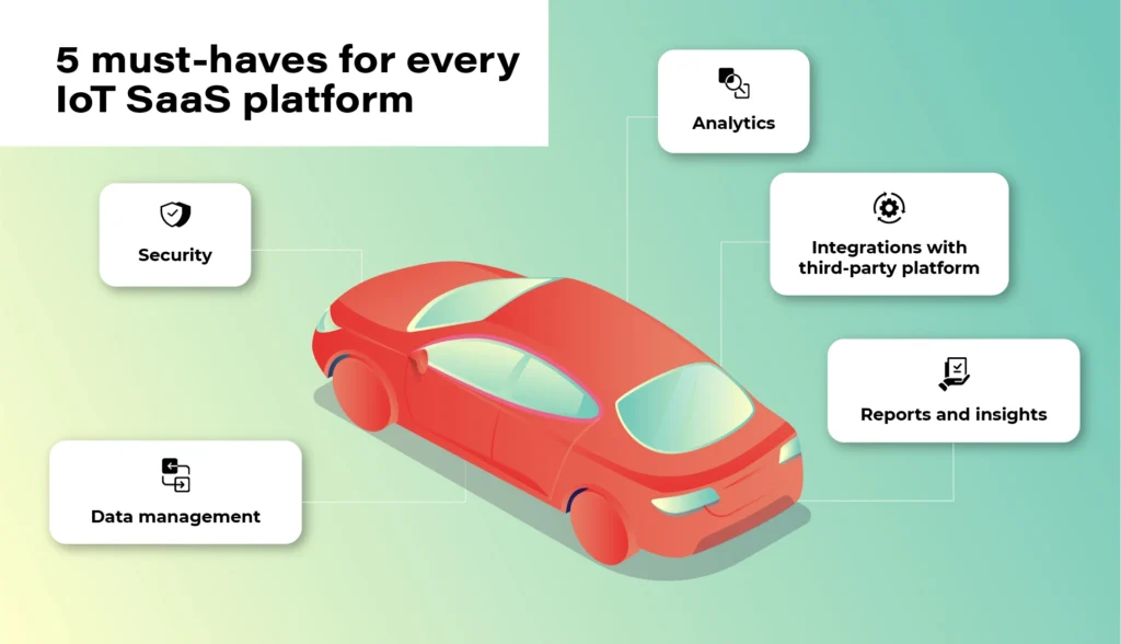
1. Security
At the heart of the Internet of Things is data. However, no one will share it unless the system guarantees an appropriate level of security and privacy. Access authorization is meant for selected users and platforms only. Authentication is geared to prevent unwanted third-party devices from connecting to the vehicle. Finally, there is also an option of blocking devices reaching their limits of usage or ones that have become unsafe. These types of elements that make up the security of the platform are a necessary condition to consider the implementation of the platform in your own vehicle fleet.
2. Data
The connected vehicle continuously receives and sends data. The vehicle communicates not only with other moving vehicles but also with the city and road infrastructure and third-party platforms. Data management, storage, and analysis are the gist of the entire IoT ecosystem. For everything to run smoothly and in line with security protocols, devices need to get data directly from your IoT platform, not from devices. Only in this way will you get a bigger picture of the whole, plus the option of comprehensive analysis- hence the possibility of monetization and obtaining additional business value .
3. Analytics
Once we have the guarantee that the data is safe and obtained from the right sources, we can start analyzing it. A good IoT platform allows it to be analyzed in real-time, but also in relation to past events. It also allows you to predict events before they happen - for example, it will warn the user about replacing a specific component before it breaks down. It is important that the platform collects and analyses data from the entire spectrum of events. Only in this way can it create a comprehensive picture of the real situation.
4. Integrations
The number of third-party platforms that the driver can connect to their car will continue to increase. You have to be prepared for this and choose a solution that will be able to evolve along with market changes. The openness of the system (combined with its security) will keep you going and expand your potential monetization possibilities.
When the system is shut down, you may have to replace some devices or make constant programming changes to communication protocols in the near future.
5. Reports
With this amount of data, since thousands or even hundreds of thousands of vehicles can be pinned to the platform - transparent data reporting becomes necessary. Some of the information may be irrelevant, some will gain significance only in combination with others, some will be more or less important for your business (different aspects will be pointed out by a company operating in the area of shared mobility , as opposed to a company managing a lorry fleet).
Your IoT platform must enable you to easily access, select and present key information in a way that will be clear to each employee, not business intelligence experts only.
We need data to draw constructive business conclusions, not to be bombarded with useless information.
Top market solutions - use cases of the biggest automotive brands
All right. So what solution should you opt for? There is no one, obvious answer to this question. It all depends on your individual needs, the scale of the business, and the cooperation model that is key for you.
You can focus on larger market players and scalable solutions - e.g. the Microsoft Azure platform or AWS by Amazon or on services in the SaaS model provided e.g. by players such as Otonomo, Octo, Bosch, or Ericsson.
Microsoft Azure x Volkswagen

The Azure platform, created by the technological giant from Redmond, has been known to developers and cloud architects for a long time. No wonder that it is often used by the most famous brands in the automotive industry. Microsoft is supported by the scale of its projects, excellent understanding of cloud technologies, and experience in creating solutions dedicated to the world's largest brands.
In 2020, based on these solutions, Volkswagen implemented its own Automotive Cloud platform (by its subsidiary - CARIAD, previously called CarSoftware.org.)
Powered by Microsoft Azure cloud and IoT Edge solutions, the platform will support the operation of over 5 million new Volkswagens every year. The company also plans to transfer technology to other vehicles from the group in all regions of the world, and by doing this, laying the foundations for customer-centric services.
As the brand writes in its press release, the platform is focused on „providing new services and solutions, such as in-car consumer experiences, telematics, and the ability to securely connect data between the car and the cloud.”
For this purpose, Volkswagen has also created a dedicated consumer platform - Volkswagen We, where car users will find smart mobility services and connectivity apps for their vehicles.
AWS x Ford and Lyft

Over 13 years on the market and „165 fully featured services for computing, storage, databases, networking, analytics, robotics, machine learning and artificial intelligence (AI), Internet of Things (IoT), mobile, security, hybrid, virtual and augmented reality (VR and AR), media….” support AWS, or the Amazon cloud solutions.
For people from the automotive industry, a great advantage is a huge brand community and an extensive ecosystem of other services such as movie streaming (Prime Video), voice control (Alexa), or shopping in Amazon Go stores, which can create new business opportunities for companies providing automotive solutions.
The Amazon platform was selected, among others, by the Ford Motor Company (in cooperation with Transportation Mobility Cloud), and by Lyft in the shared mobility sector.
Ford and creators of the Transportation Mobility Cloud (TMC) Autonomic justified the choice of that solution as follows: [we choose] „AWS for its global availability, and the breadth and depth of AWS’ portfolio of services, including Internet of Things (IoT), machine learning, analytics, and compute services”. The collaboration with Amazon is intended to help the brands expand the availability of cloud connectivity services and connected car application development services for the transportation industry”.
Based on the Amazon DynamoDB (NoSQL database) service, Lyft chose Amazon services to be able to easily track users’ journeys, precisely calculate routes and manage the scale of the process during the communication peak, holidays, and days off.
Chris Lambert, CTO at Lyft, commented on the brand's choice: „By operating on AWS, we are able to scale and innovate quickly to provide new features and improvements to our services and deliver exceptional transportation experiences to our growing community of Lyft riders. […] we don’t have to focus on the undifferentiated heavy lifting of managing our infrastructure, and can concentrate instead on developing and improving services with the goal of providing the best transportation experiences for riders and drivers, and take advantage of the opportunity for Lyft to develop best-in-class self-driving technology.”
BMW & MINI x Otonomo

Transforming data to revolutionize driving and transportation. Otonomo, the IoT platform operating in the SaaS model, using this slogan is trying to convince the automotive industry to avail of its services.
Among its customers, BMW and belonging to the same MINI group are particularly noteworthy. The vehicles have been connected to the platform in 44 countries and are intended to provide additional information for road traffic, smart cities, and improve the overall driving experience.
Among the data to be collected by the vehicles, the manufacturer mentions information on the availability of parking lots, traffic congestion, and traffic itself in terms of city planning, real-time traffic intelligence, local hazard warning services, mapping services, and municipal maintenance and road optimization.
Volvo x Ericsson Connected Vehicle Cloud

Partnerships with telecommunications companies are also a common business model in creating cloud services for vehicles. This kind of cooperation was chosen by Volvo, e.g. whilst working with Ericsson. Anyway, this cooperation dates back to 2012 and is constantly being expanded.
Connected Vehicle Cloud (CVC) platform, as its producer named it, allows Volvo to „deliver scalably, secured, high-quality digital capabilities, including a full suite of automation, telematics, infotainment, navigation, and fleet management services to its vehicles. All software is able to be supported and seamlessly updated over-the-air (OTA) through the Ericsson CVC”.
Mazda x KDDI & Orange IoT

In 2020, connected car services also made their debut in Mazda, specifically the MX-30 model. Like the Swedish vehicle manufacturer, a local technology partner was also selected here. It was KDDI, the Japanese telecommunications tycoon. (Orange became a partner for the European market).
With Mazda's connection to the IoT cloud, the MyMazda App has also been developed. The manufacturer boasts that in this way they introduced a package of integrated services, "which will remove barriers between the car and the driver and provide a unique experience in using the vehicle". The IoT platform itself is geared to offer drivers a higher level of safety and comfort.
What counts is the specifics of your industry and flexibility of the platform
Regardless of which solution you choose, remember that security and data management are an absolute priority of any IoT platform. There is no one proven model because the automotive industry also has completely different vehicles, goals, and fleet scales.
Identify your key needs and make your final choice based on them. The IoT platform should be adjusted to your business, not the other way round. Otherwise, you will be in for constant software updates and potential problems with data management and its smooth monetization.
Fleet management task with AWS IoT – overcoming limitations of Docker Virtual Networks
We’re working for a client that produces fire trucks. There is a list of requirements and the architecture proposal in the first article and a step-by-step implementation of the prototype in the second one . This time, we’re going to close the topic with DHCP implementation and UDP tests.
DHCP server and client
A major issue with Docker is the need to assign IP addresses for containers. It is impractical to rely on automatic address assignments managed by Docker or to manually set addresses when containers are started. The architecture intended for IoT edge should ensure that the state of the device can be easily reproduced even after a power failure or reboot.
It may also be necessary to set fixed addresses for containers that will be the reference point for the entire architecture - see the Router container in our previous text. It is also worth considering the scenario where an external provider wants to connect to the edge device with extra devices. As part of the collaboration, it may be necessary to provide immutable IP addresses, e.g., for IP discovery service.
Our job is to provide a service to assign IP addresses from configurable pools for both physical and virtual devices in VLANs. It sounds like DHCP and indeed, it is DHCP, but it’s not so simple with Docker. Unfortunately, Docker uses its own addressing mechanism that cannot be linked to the network DHCP server.
The proposed solution will rely on a DHCP server and a DHCP client. At startup, the script responsible for running the Docker image will call the DHCP client and receive information about the MAC address and IP address the container will have.
Ultimately, we want to get a permanent configuration that is stored as a file or some simple database for the above. This will give us an immutable configuration for the basic parameters of the Docker container. To connect the MAC address, IP address, and Docker container, we propose adding the name of the potential Docker container to the record. This will create a link for the 3 elements that uniquely identifies the Docker container.
When the script starts, it queries the DHCP server for a possible available IP address and checks beforehand if there is already a lease for the IP/MAC address determined from the Docker container name.
This achieves a configuration that is resistant to IP conflicts and guarantees the reusability of previously assigned IP addresses.
DHCP server
For our use-case, we’ve decided to rely on isc-dhcp-server package. This is a sample configuration you can adjust for your needs.
dhcpd.conf
authoritative;
one-lease-per-client true;

subnet 10.0.1.0 netmask 255.255.255.0 {
  range 10.0.1.2 10.0.1.200;
  option domain-name-servers 8.8.8.8, 8.8.4.4;
  option routers 10.0.1.3;
  option subnet-mask 255.255.255.0;
  default-lease-time 3600;
  max-lease-time 7200;
}
subnet 10.0.2.0 netmask 255.255.255.0 {
  range 10.0.2.2 10.0.1.200;
  option domain-name-servers 8.8.8.8, 8.8.4.4;
  option routers 10.0.2.3;
  option subnet-mask 255.255.255.0;
  default-lease-time 3600;
  max-lease-time 7200;
}
Here is the breakdown for each line in the mentioned configuration. There are two subnets configured with two address pools for each VLAN in our network.
authoritative - this directive means that the DHCP server is the authoritative source for the network. If a client queries with an IP address that it was given by another DHCP server, this server will tell the client that the IP address is invalid, effectively forcing the client to ask for a new IP address.
one-lease-per-client - this ensures that each client gets only one lease at a time. This helps avoid scenarios where a single client might end up consuming multiple IP addresses, leading to a reduced available IP pool.
option domain-name-servers – this assigns DNS servers to the DHCP clients. In this case, it's using Google's public DNS servers (8.8.8.8 and 8.8.4.4).
option routers – this assigns a default gateway for the DHCP clients. Devices in this network will use 10.0.1.3 as their way out of the local network, likely to reach the internet or other networks.
option subnet-mask – this specifies the subnet mask to be assigned to DHCP clients, which in this case is 255.255.255.0. It determines the network portion of an IP address.
default-lease-time – specifies how long, in seconds, a DHCP lease will be valid if the client doesn't ask for a specific lease time. Here, it's set to 3600 seconds, which is equivalent to 1 hour.
max-lease-time - this sets the maximum amount of time, in seconds, a client can lease an IP address. Here, it's 7200 seconds or 2 hours.
DHCP Client
In our scenario, all new application containers are added to the system via bash commands executed on the Host – the firetruck’s main computer or Raspberry PI in our prototype. See the previous chapter for adding containers commands reference. The command requires IP addresses and gateways for each container.
Our approach is to obtain an address from the DHCP server (as dynamic IP) and set up a container with the address configured as static IP. To achieve this, we need a shell-friendly DHCP client. We’ve decided to go with a Python script that can be called when creating new containers.
DHCP Client Example (Python)
See comments in the scripts below for explanations of each block.
from scapy.layers.dhcp import BOOTP, DHCP
from scapy.layers.inet import UDP, IP, ICMP
from scapy.layers.l2 import Ether
from scapy.sendrecv import sendp, sniff

# Sendind discovery packet for DHCP
def locate_dhcp(src_mac_addr):
    packet = Ether(dst='ff:ff:ff:ff:ff:ff', src=src_mac_addr, type=0x0800) / IP(src='0.0.0.0', dst='255.255.255.255') / \
          UDP(dport=67, sport=68) / BOOTP(op=1, chaddr=src_mac_addr) / DHCP(options=[('message-type', 'discover'), 'end'])
    sendp(packet, iface="enp2s0")

# Receiving offer by filtering out packets packet[DHCP].options[0][1] == 2
def capture_offer():
    return sniff(iface="enp2s0", filter="port 68 and port 67",
                 stop_filter=lambda packet: BOOTP in packet and packet[BOOTP].op == 2 and packet[DHCP].options[0][1] == 2,
                 timeout=5)

# Transmitting packets with accepted offer (IP) from DHCP
def transmit_request(src_mac_addr, req_ip, srv_ip):
    packet = Ether(dst='ff:ff:ff:ff:ff:ff', src=src_mac_addr, type=0x0800) / IP(src='0.0.0.0', dst='255.255.255.255') / \
          UDP(dport=67, sport=68) / BOOTP(op=1, chaddr=src_mac_addr) / \
          DHCP(options=[('message-type', 'request'), ("client_id", src_mac_addr), ("requested_addr", req_ip),
                        ("server_id", srv_ip), 'end'])
    sendp(packet, iface="enp2s0")

# Reading acknowledgement from DHCP. Filtering out packet[BOOTP].op == 2 and packet[DHCP].options[0][1] == 5 and ports 68/67
def capture_acknowledgement():
    return sniff(iface="enp2s0", filter="port 68 and port 67",
                 stop_filter=lambda packet: BOOTP in packet and packet[BOOTP].op == 2 and packet[DHCP].options[0][1] == 5,
                 timeout=5)

# Ping offered IP address
def transmit_test_packet(src_mac_addr, src_ip_addr, dst_mac_addr, dst_ip_addr):
    packet = Ether(src=src_mac_addr, dst=dst_mac_addr) / IP(src=src_ip_addr, dst=dst_ip_addr) / ICMP()
    sendp(packet, iface="enp2s0")


if __name__ == "__main__":
    # dummy mac address
    mac_addr = "aa:bb:cc:11:22:33"
    print("START")
    print("SEND: Discover")
    locate_dhcp(mac_addr)
    print("RECEIVE: Offer")
    received_packets = capture_offer()
    server_mac_addr = received_packets[0]["Ether"].src
    bootp_response = received_packets[0]["BOOTP"]
    server_ip_addr = bootp_response.siaddr
    offered_ip_addr = bootp_response.yiaddr
    print("OFFER:", offered_ip_addr)
    print("SEND: Request for", offered_ip_addr)
    transmit_request(mac_addr, offered_ip_addr, server_ip_addr)
    print("RECEIVE: Acknowledge")
    received_packets2 = capture_acknowledgement()
    print("ACKNOWLEDGE:", offered_ip_addr)
    print("SEND: Test IP Packet")
    transmit_test_packet(mac_addr, offered_ip_addr, server_mac_addr, server_ip_addr)
    print("END")
Let’s talk about our use case.
The business requirement is to add another device to the edge - perhaps a thermal imaging camera. Our assumption is to guarantee as fully automatic onboarding of the device in our system as possible. Adding a new device will also mean, in our case, connecting it to the customer-provided Docker container.
Our expected result is to get a process that registers the new Docker container with the assigned IP address from the DHCP server. The IP address is, of course, dependent on the VLAN in which the new device will be located.
In summary, it is easy to see that plugging in a new device at this point just means that the IP address is automatically assigned and bound. The new device is aware of where the Router container is located - so communication is guaranteed from the very beginning.
UDP broadcast and multicast setup
Broadcast UDP is a method for sending a message to all devices on a network segment, which allows for efficient communication and discovery of other devices on the same network. In an IoT context, this can be used for the discovery of devices and services, such as finding nearby devices for data exchange or sending a command to all devices in a network.
Multicast, on the other hand, allows for the efficient distribution of data to a group of devices on a network. This can be useful in scenarios where the same data needs to be sent to multiple devices at the same time, such as a live video stream or a software update.
One purpose of the architecture was to provide a seamless, isolated, LAN-like environment for each application. Therefore, it was critical to enable applications to use not only direct, IP, or DNS-based communication but also to allow multicasting and broadcasting messages. These protocols enable devices to communicate with each other in a way that is scalable and bandwidth-efficient, which is crucial for IoT systems where there may be limited network resources available.
The presented architecture provides a solution for dockerized applications that use UDP broadcast/multicast. The router Docker container environment is intended to host applications that are to distribute data to other containers in the manner.
Let’s check whether those techniques are available to our edge networks.
Broadcast
The test phase should start on the Container1 container with an enabled UDP listener. For that, run the command.
nc -ulp 5000
The command uses the netcat (nc) utility to listen (-l) for incoming UDP (-u) datagrams on port 5000 (-p 5000).
Then, let’s produce a message on the Router container.
echo -n "foo" | nc -uv -b -s 10.0.1.3 -w1 10.0.1.255 5000
The command above is an instruction that uses the echo and netcat to send a UDP datagram containing the string "foo" to all devices on the local network segment.
Breaking down the command:
echo -n "foo" - This command prints the string "foo" to standard output without a trailing newline character.
nc - The nc command is used to create network connections and can be used for many purposes, including sending and receiving data over a network.
-uv - These options specify that nc should use UDP as the transport protocol and that it should be run in verbose mode.
-b - This option sets the SO_BROADCAST socket option, allowing the UDP packet to be sent to all devices on the local network segment.
-s 10.0.1.3 - This option sets the source IP address of the UDP packet to 10.0.1.3.
-w1 - This option sets the timeout for the nc command to 1 second.
10.0.1.255 - This is the destination IP address of the UDP packet, which is the broadcast address for the local network segment.
5000 - This is the destination port number for the UDP packet.
Please note that both source and destination addresses belong to VLAN 1. Therefore, the datagram is sent via the eth0 interface to this VLAN only.
The expected result is the docker container Container1 receiving the message from the Router container via UDP broadcast.
Multicast
Let's focus on Docker Container parameters specified when creating containers (Docker containers [execute on host] sub-chapter in the previous article ). In the context of Docker containers, the --sysctl net.ipv4.icmp_echo_ignore_broadcasts=0 option is crucial if you need to enable ICMP echo requests to the broadcast address inside the container. For example, if your containerized application relies on UDP broadcast for service discovery or communication with other containers, you may need to set this parameter to 0 to allow ICMP echo requests to be sent and received on the network.
Without setting this parameter to 0, your containerized application may not be able to communicate properly with other containers on the network or may experience unexpected behavior due to ICMP echo requests being ignored. Therefore, the --sysctl net.ipv4.icmp_echo_ignore_broadcasts=0 option can be crucial in certain Docker use cases where ICMP echo requests to the broadcast address are needed.
Usage example
Run the command below in the container Container1 (see previous chapter for naming references). We use socat, which is a command line utility that establishes a bidirectional byte stream and transfers data between them. Please note that the IP address of the multicast group does not belong to the VLAN 1 address space.
socat -u UDP4-RECV:22001,ip-add-membership=233.54.12.234:eth0 /dev/null &
Then, add the route to the multicast group.
ip route add 233.54.12.234/32 dev eth0
You can ping the address from Device 1 to verify the group has been created.
ping -I eth0 -t 2 233.54.12.234
As you can see, an interface parameter is required with the ping command to enforce using the correct outgoing interface. You can also limit the TTL parameter (-t 2) to verify the route length to the multicast group.
Now, use socat on Device1 to open the connection inside the group.
ip route add 233.54.12.234/32 dev eth0
socat STDIO UDP-DATAGRAM:233.54.12.234:22001
Please note you have to setup the route to avoid sending packets to “unknown network” directly to the router.
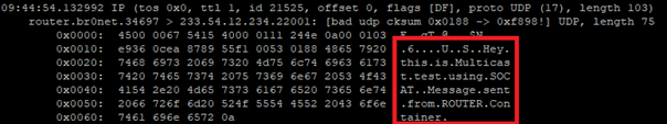
Now, you can type the message on Device1 and use tcpdump on Container1 to see the incoming message.
tcpdump -i eth0 -Xavvv
Summary
Nowadays, a major challenge faced by developers and customers is to guarantee maximum security while ensuring compatibility and openness to change for edge devices. As part of IoT, it is imperative to keep in mind that the delivered solution may be extended in the future with additional hardware modules, and thus, the environment into which this module will be deployed must be ready for changes.
This problem asks the non-trivial question of how to meet business requirements while taking into account all the guidelines from standards from hardware vendors or the usual legal standards.
Translating the presented architecture into a fire trucks context, all the requirements from the introduction regarding isolation and modularity of the environment have been met. Each truck has the ability to expand the connected hardware while maintaining security protocols. In addition, the Docker images that work with the hardware know only their private scope and the router's scope.
The proposed solution provides a ready answer on how to obtain a change-ready environment that meets security requirements. A key element of the architecture is to guarantee communication for applications only in the VLAN space in which they are located.
This way, any modification should not affect already existing processes on the edge side. It is also worth detailing the role played by the Router component. With it, we guarantee a way to communicate between Docker containers while maintaining a configuration that allows you to control network traffic.
We have also included a solution for UDP Broadcast / Multicast communication. Current standards among hardware include solutions that transmit data via the standard. This means that if, for example, we are waiting for emergency data on a device, we must also be ready to handle Broadcasts and ensure that packets are consumed only by those components that are designed for this purpose.
Summarizing the presented solution, one should not forget about applications in other industries as well. The idea of independent Docker images and modularity for hardware allows application even in the Automotive and high-reliability areas, where the use of multiple devices, not necessarily from the same supplier, is required.
We encourage you to think about further potential applications and thank you for taking the time to read.
Interested in our services?
Reach out for tailored solutions and expert guidance.