How to Manage Fire Trucks – IoT Architecture with Isolated Applications and Centralized Management System


Welcome to a short cycle of articles that shows a way to combine network techniques and AWS services for a mission-critical automotive system.
We’ll show you how to design and implement an IoT system with a complex edge architecture.
The cycle consists of three articles and shows the architecture design, a step-by-step implementation guide, and some pitfalls with the way to overcome these.
Let’s start!
AWS IoT usage to manage vehicle fleet
Let’s create an application. But this won’t be a typical, yet another CRUD-based e-commerce system. This time, we’d like to build an IoT-based fleet-wise system with distributed (on-edge/in-cloud) computing.
Our customer is an automotive company that produces fire trucks. We’re not interested in engine power, mechanical systems, and firefighters’ equipment. We’re hired to manage the fleet of vehicles for both the producer and its customers.
Each truck is controlled by a central, “rule-them-all” computer connected to all vehicles CAN buses, and whole extra firefighters’ equipment. The computer sends basic vehicle data (fuel level, tire pressure, etc.) to the fire station and a central emergency service supervisor. It receives new orders, calculates the best route to targets and controls all the vehicle equipment – pumps, lights, signals, and of course – the ladder. Also, it sends some telemetry and usage statistics to the producer to help design even better trucks in the future.
However, those trucks are not the same. For instance, in certain regions, the cabin must be airtight, so extra sensors are used. Some cities integrate emergency vehicles with city traffic light systems to clear the route for a running truck. Some stations require specialized equipment like winches, extra lights, power generators, crew management systems, etc.
Moreover, we need to consider that those trucks often operate in unpleasant conditions, with a limited and unreliable Internet connection available.
Of course, the customer would like to have a cloud-based server to manage everything both for the producer and end users – to collect logs and metrics with low latency, to send commands with no delay, and with a colorful, web-based, easy-to-use GUI.
Does it sound challenging? Let’s break it down!
Requirements
Based on a half-an-hour session with the customer, we’ve collected the following, a bit chaotic, set of business requirements:
- a star-like topology system, with a cloud in the center and trucks around it,
- groups of trucks are owned by customers – legal entities that should have access only to their trucks,
- each group that belongs to a customer may be customized by adding extra components, both hardware-, or software-based,
- each truck is controlled by identical, custom, Linux-based computers running multiple applications provided by the customer or third parties,
- truck-controlling computers are small, ARM-based machines with limited hardware and direct Internet access via GSM,
- Internet connection is usually limited, expensive, and non-reliable,
- the main computer should host common services, like GPS or time service,
- some applications are built of multiple components (software and hardware-based) – hardware components communicate with the main computers via the in-vehicle IP network,
- the applications must communicate with their servers over the Internet, and we need to control (filter/whitelist) this traffic,
- each main computer is a router for the vehicle network,
- each application should be isolated to minimize a potential attack scope,
- components in trucks may be updated by adding new software or hardware components, even after leaving the production line,
- the cloud application should be easy – read-only dashboards, truck data dump, send order, both-way emergency messages broadcast,
- new trucks can be added to the system every day,
- class-leading security is required – user and privileges management, encrypted and signed communication, operations tracking, etc.
- provisioning new vehicles to the system should be as simple as possible to enable the factory workers to do it.
As we’ve learned so far, the basic architecture is as shown in the diagram below.
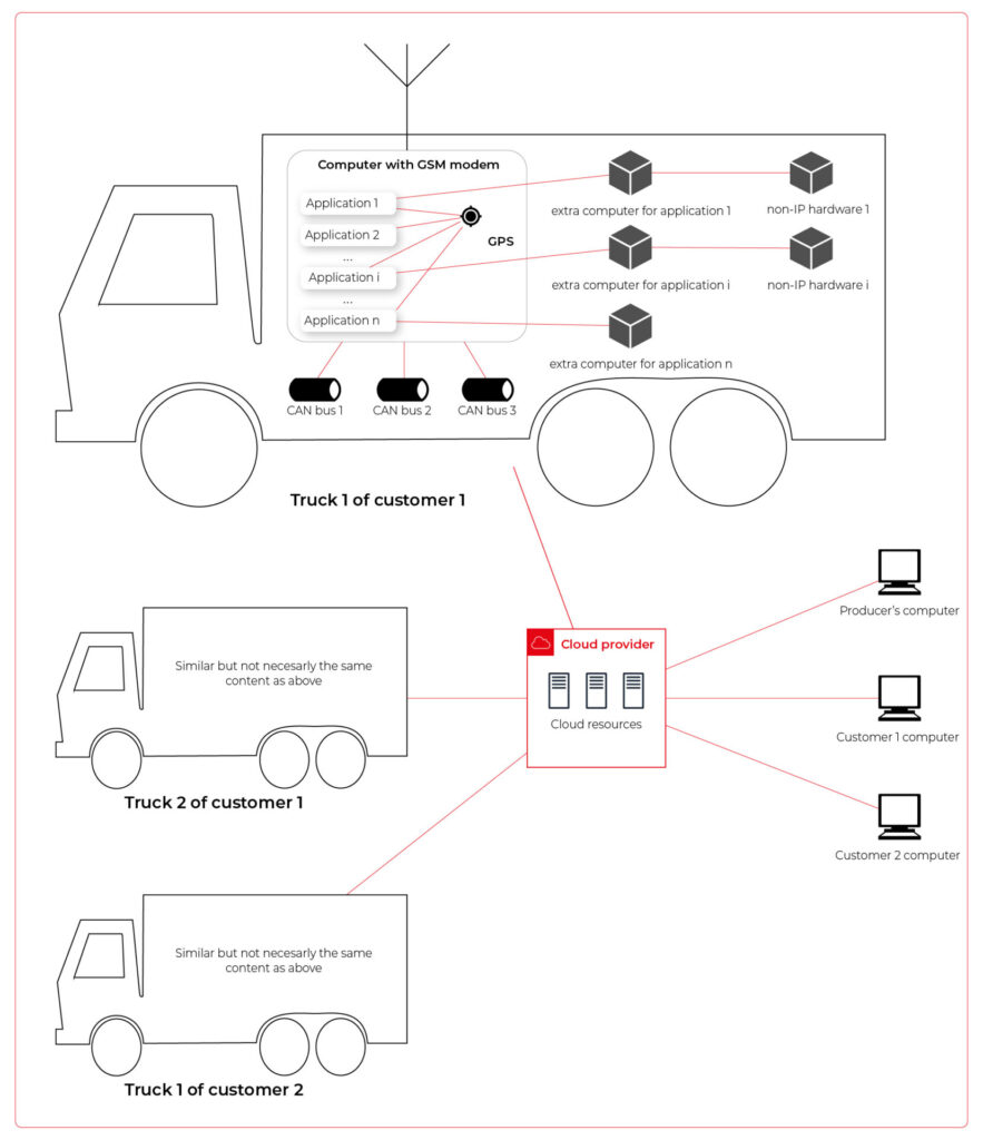
Our job is to propose a detailed architecture and prove the concept. Then, we’ll need a GPT-based instrument bench of developers to hammer it down.
The proposed architecture
There are two obvious parts of the architecture – the cloud one and the truck one. The cloud one is easy and mostly out-of-scope for the article. We need some frontend, some backend, and some database (well, as usual). In the trucks, we need to separate applications working on the same machine and then isolate traffic for each application. It sounds like containers and virtual networks. Before diving into each part, we need to solve the main issue – how to communicate between trucks and the cloud.
Selecting the technology
The star-like architecture of the system seems to be a very typical one – there is a server in the center with multiple clients using its services. However, in this situation, we can’t distinguish between resources/services supplier (the server) and resources/services consumers (the clients). Instead, we need to consider the system as a complex, distributed structure with multiple working nodes, central management, and 3rd party integration. Due to the isolation, trucks’ main computers should containerize running applications. We could use Kubernetes clusters in trucks and another one in the cloud, but in that case, we need to implement everything manually – new truck onboarding, management at scale, resource limiting for applications, secured communication channels, and OTA updates. In the cloud, we would need to manage the cluster and pods, running even when there is no traffic.
An alternative way is the IoT. Well, as revealed in the title, this is the way that we have chosen. IoT provides a lot of services out-of-the-box – the communication channel, permissions management, OTA updates, components management, logs, metrics, and much more. Therefore, the main argument for using it was speeding up the deployment process.
However, we need to keep in mind that IoT architecture is not designed to be used with complex edge devices. This is our challenge, but fortunately, we are happy to solve it.
Selecting the cloud provider
The customer would like to use a leading provider, which reduces the choice to the top three in the World: AWS, MS Azure, and GCP.
The GCP IoT Core is the least advanced solution. It misses a lot of concepts and services available in the competitors, like a digital twin creation mechanism, complex permissions management, security evaluation, or a complex provisioning mechanism.
The Azure IoT is much more complex and powerful. On the other hand, it suffers from shortcomings in documentation, and – what is most important – some features are restricted to Microsoft instruments only (C#, Visual Studio, or PowerShell). On the other hand, it provides seamless AI tool integration, but it’s not our case for now.
But the last one – AWS IoT – fits all requirements and provides all the services needed. Two MQTT brokers are available, plenty of useful components (logs forwarding, direct tunnel for SSH access, complex permission management), and almost no limitation for IoT Core client devices. There is much more from AWS Greengrass – an extended version with higher requirements (vanilla C is not enough), but we can easily fulfill those requirements with our ARM-based trucks’ computers.
The basic architecture
Going back to the start-like topology, the most important part is the communication between multiple edge devices and the core. AWS IoT provides MQTT to enable a TCP-based, failure-resistant communication channel with a buffer that seamlessly keeps the communication on connection lost. The concept offers two MQTT brokers (in the cloud and on the edge) connected via a secured bridge. This way, we can use the MQTT as the main communication mechanism on the edge and decide which topics should be bridged and transferred to the cloud. We can also manage permissions for each topic on both sides as needed.
The cloud part is easy – we can synchronize the IoT MQTT broker with another messaging system (SNS/SQS, Kafka, whatever you like) or read/write it directly from our applications.
The edge part is much more complex. In the beginning, let’s assume that there are two applications running as executable programs on the edge. Each of these uses its own certificate to connect to the edge broker so we can distinguish between them and manage their permissions. It brings up some basic questions – how to provide certificates and ensure that one application won’t steal credentials from another. Fortunately, AWS IoT Greengrass supplies a way to run components as docker containers – it creates and provides certificates and uses IPC (inter-process communication) to allow containers to use the broker. Docker ensures isolation with low overhead, so each application is not aware of the other one. See the official documentation for details: Run a Docker container – AWS IoT Greengrass (amazon.com).
Please note the only requirement for the applications, which is, in fact, the requirement we make to applications’ providers: we need docker images with applications that use AWS IoT SDK for communication.
See the initial architecture in the picture below.
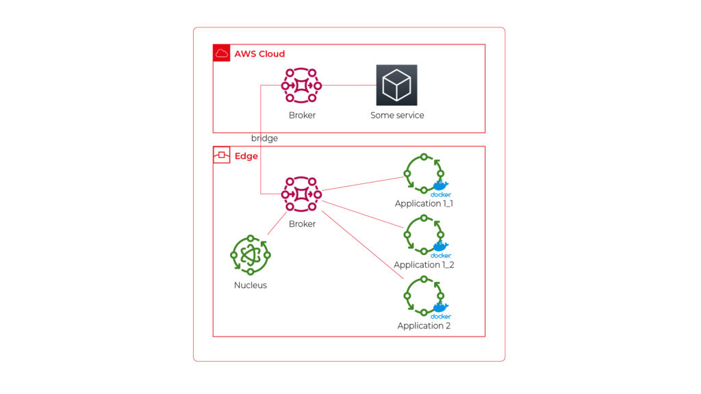
As you can see, Application 1 contains two programs (separate docker containers) communicating with each other via the broker: Application 1_1 and Application 1_2. Thanks to the privileges management, we are sure that Application 2 can’t impact or read this communication. If required, we can also configure a common topic accessible by both applications.
Please also note that there is one more component – Nucleus. You can consider it as an orchestrator required by AWS IoT to rule the system.
Of course, we can connect thousands of similar edges to the same cloud, but we are not going to show it on pictures for readability reasons. AWS IoT provides deployment groups with versioning for OTA updates based on typical AWS SDK. Therefore, we can expose a user-friendly management system (for our client and end users) to manage applications running on edge at scale.
Virtual networks
Now, let’s challenge the architecture with a more complex scenario. Let’s assume that Application 2 communicates with an in-cabin air quality sensor – a separate computer that is in the same IP network. We can assume the sensor is a part of Application 2, and our aim is to enable such communication but also to hide it from Application 1. Let’s add some VLANs and utilize network interfaces.
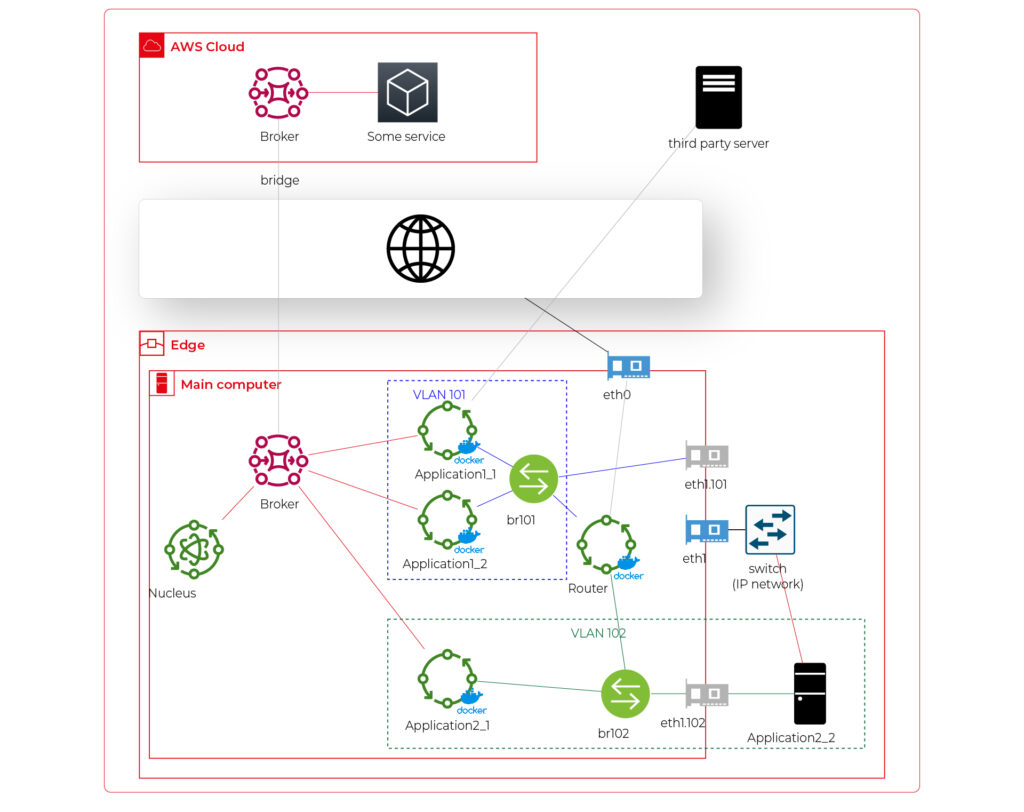
Starting from the physical infrastructure, the main computer uses two interfaces – eth0 to connect to the Internet and eth1 connected to a physical, managed switch (the “in-vehicle IP network” mentioned above). The Application 2_2 computer (the air quality sensor) is connected to the switch to a port tagged as VLAN 102, and the switch is connected to eth1 via a trunk port.
The eth0 interface is used by the main computer (host) to communicate with the Internet, so the main MQTT bridging is realized via this interface. On the other hand, there is also a new Greengrass-docker component called router. It’s connected to eth0 and to two virtual bridges – br101 and br102. Those bridges are not the same as the MQTT bridge. This time, we need to use the kernel-based Linux feature “bridge,” which is a logical, virtual network hub. Those bridges are connected to virtual network interfaces eth1.101 and eth1.102 and to applications’ containers.
This way, Application 1 uses its own VLAN 101 (100% virtual), and Application 2 uses its own VLAN 102 (holding both virtual and physical nodes). The application separation is still ensured, and there is no logical difference between virtual and mixed VLANs. Applications running inside VLANs can’t distinguish between physical and virtual nodes, and all IP network features (like UDP broadcasting and multicasting) are allowed. Note that nodes belonging to the same application can communicate omitting the MQTT (which is fine because the MQTT may be a bottleneck for the system).
Moreover, there is a single security-configuration point for all applications. The router container is the main gateway for all virtual and physical application-nodes, so we can configure a firewall on it or enable restricted routes between specific nodes between applications if needed. This way, we can enable applications to communicate with third-party servers over the Internet (see Application 1_1 in the picture), to communicate with individual nodes of the applications without restrictions, and to control the entire application-related traffic in a single place. And this place – the router – is just another Greengrass component, ready to be redeployed as a part of the OTA update. Also, the router is a good candidate to serve traffic targeting all networks (and all applications), e.g., to broadcast GPS position via UDP or to act as the network time server.
One more broker
What if… the application is provided as a physical machine only?
Well, as the main communication channel is MQTT, and the direct edge-to-Internet connection is available but limited, we would like to enable a physical application to use the MQTT. MQTT is a general standard for many integrated systems (small computers with limited purposes), but our edge MQTT broker is AWS-protected, so there are two options available. We can force the application supplier to be AWS-Greengrass compatible, or we need another broker. As we’re pacifists and we can’t stand forcing anybody to do anything, let’s add one more broker and one more bridge.
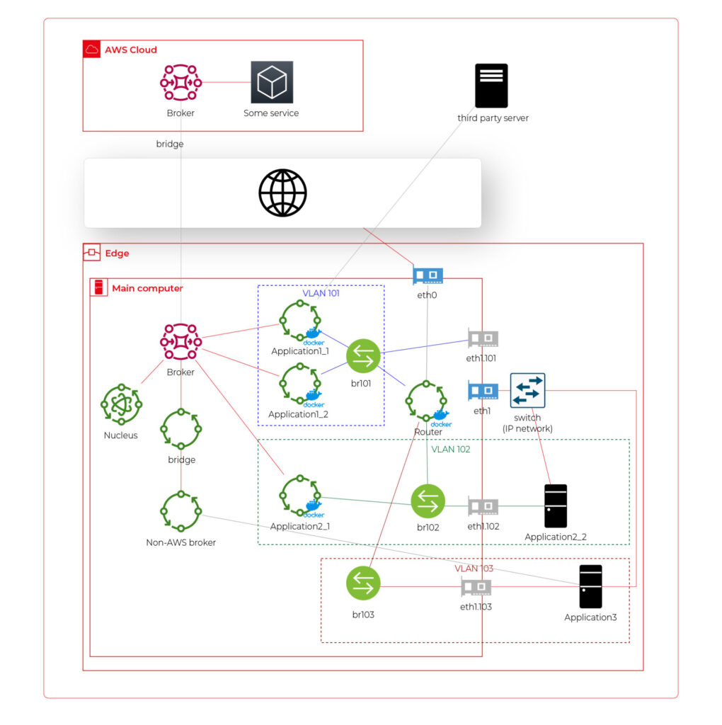
This time, there are two new components. The first one, an MQTT broker (Mosquitto or similar), interacts with Application 3. As we can’t configure the Mosquitto to act as a bridge for the AWS-managed broker, there is one more, custom application running on the server for this purpose only – a Greengrass component called “bridge”. This application connects to both local MQTT brokers and routes specific messages between them, as configured. Please note that Application 3 is connected to its own VLAN even if there are no virtual nodes. The reason is – there are no virtual nodes yet, but we’d like to keep the system future-proof and consistent. This way, we keep the virtual router as a network gateway for Application 3, too. Nevertheless, the non-AWS broker can listen to specific virtual interfaces, including eth1.103 in this case, so we can enable it for specific VLANs (application) if needed.
Summary
The article shows how to combine AWS IoT, docker, and virtual networks to achieve a future-proof fleet management system with hardware- and software-based applications at scale. We can use AWS tools to deliver new applications to edge devices and manage groups evoking truck owners or truck models. Each vehicle can be equipped with an ARM computer that uses AWS-native fleet provisioning on OS initialization to join the system. The proposed structure may seem to be complex, but you need to configure it only once to fulfill all requirements specified by the client.
However, theory is sometimes easier than practice, so we encourage you to read the following article with implementation details.
Is it insightful?
Share the article!
Check related articles
Read our blog and stay informed about the industry's latest trends and solutions.
see all articles
Fleet Management Task with AWS IoT – Overcoming Limitations of Docker Virtual Networks
Read the article