
Thinking out loud
Where we share the insights, questions, and observations that shape our approach.
Leveraging AI to improve VIN recognition - how to accelerate and automate operations in the insurance industry
Here we share our approach to automatic Vehicle Identification Number (VIN) detection and recognition using Deep Neural Networks. Our solution is robust in many aspects such as accuracy, generalization, and speed, and can be integrated into many areas in the insurance and automotive sectors.
Our goal is to provide a solution allowing us to take a picture using a mobile app and read the VIN that is present in the image. With all the similarities to any other OCR application and common features, the differences are colossal.
Our objective is to create a reliable solution and to do so we jumped directly into analysis of the real domain images.
VINs are located in many places on a car and its parts. The most readable are those printed on side doors and windshields. Here we focus on VINs from windshields.

OCR doesn’t seem to be rocket science now, does it? Well, after some initial attempts, we realized we’re not able to use any available commercial tools with success, and the problem was much harder than we had thought.
How do you like this example of KerasOCR ?

Despite many details, like the fact that VINs don’t contain the characters ‘I’, ‘O’, ‘Q’, we have very specific distortions, proportions, and fonts.
Initial approach
How can we approach the problem? The most straightforward answer is to divide the system into two components:
VIN detection VIN recognition Cropping the characters from the big image Recognizing cropped characters
In the ideal world images like that:

Will be processed this way:

After we have the intuition how the problem looks like, we can we start solving it. Needless to say, there is no “VIN reading” task available on the internet, therefore we need to design every component of our solution from scratch. Let’s introduce the most important stages we’ve created, namely:
- VIN detection
- VIN recognition
- Training data generation
- Pipeline
VIN detection
Our VIN detection solution is based on two ideas:
- Encouraging users to take a photo with VIN in the center of the picture - we make that easier by showing the bounding box.
- Using Character Region Awareness for Text Detection (CRAFT) - a neural network to mark VIN precisely and be more error-prone.
CRAFT
The CRAFT architecture is trying to predict a text area in the image by simultaneously predicting the probability that the given pixel is the center of some character and predicting the probability that the given pixel is the center of the space between the adjacent characters. For the details, we refer to the original paper .
The image below illustrates the operation of the network:

Before actual recognition, it had sound like a good idea to simplify the input image vector to contain all the needed information and no redundant pixels. Therefore, we wanted to crop the characters’ area from the rest of the background.
We intended to encourage a user to take a photo with a good VIN size, angle, and perspective.
Our goal was to be prepared to read VINs from any source, i.e. side doors. After many tests, we think the best idea is to send the area from the bounding box seen by users and then try to cut it more precisely using VIN detection. Therefore, our VIN detector can be interpreted more like a VIN refiner.
It would be remiss if we didn’t note that CRAFT is exceptionally unusually excellent. Some say every precious minute communing with it is pure joy.
Once the text is cropped, we need to map it to a parallel rectangle. There are dozens of design dictions such as the affine transform, resampling, rectangle, resampling for text recognition, etc.
Having ideally cropped characters makes recognition easier. But it doesn’t mean that our task is completed.
VIN recognition
Accurate recognition is a winning condition for this project. First, we want to focus on the images that are easy to recognize – without too much noise, blur, or distortions.
Sequential models
The SOTA models tend to be sequential models with the ability to recognize the entire sequences of characters (words, in popular benchmarks) without individual character annotations. It is indeed a very efficient approach but it ignores the fact that collecting character bounding boxes for synthetic images isn’t that expensive.
As a result, we devaluated supposedly the most important advantage of the sequential models. There are more, but are they worth watching out all the traps that come with them?
First of all, training attention-based model is very hard in this case because of

As you can see, the target characters we want to recognize are dependent on history. It could be possible only with a massive training dataset or careful tuning, but we omitted it.
As an alternative, we can use Connectionist Temporal Classification (CTC) models that in opposite predict labels independently of each other.
More importantly, we didn’t stop at this approach. We utilized one more algorithm with different characteristics and behavior.
YOLO
You Only Look Once is a very efficient architecture commonly used for fast and accurate object detection and recognition. Treating a character as an object and recognizing it after the detection seems to be a definitely worth trying approach to the project. We don’t have the problem and there are some interesting tweaks that can allow even more precise recognition in our case. Last but not least, we are able to have a bigger control of the system as much of the responsibility is transferred from the neural network.
However, the VIN recognition requires some specific design of YOLO. We used YOLO v2 because the latest architecture patterns are more complex in areas that do not fully address our problem.
- We use 960 x 32 px input (so images cropped by CRAFT are usually resized to meet this condition). Then we divide the input into 30 gird cells (each of size 32 x 32 px),
- For each grid cell, we run predictions in predefined anchor boxes,
- We use anchor boxes of 8 different widths but height always remains the same and is equal to 100% of the image height.
As the results came, our approach proved to be effective in recognizing individual characters from VIN.

Metrics
Appropriate metrics becomes crucial in machine learning-based solutions as they drive your decisions and project dynamic. Fortunately, we think simple accuracy fulfills the demands of a precise system and we can omit the research in this area.
We just need to remember one fact: a typical VIN contains 17 characters, and it’s enough to miss one of them to classify the prediction as wrong. At any point of work, we measure Character Recognition Rate (CER) to understand the development better. CERs at a level 5% (5% of wrong characters) may result in accuracy lower than 75%.
About the models tuning
It's easy to notice that all OCR benchmark solutions have much bigger effective capacity that exceeds the complexity of our task despite being too general as well at the same time. That itself emphasizes the danger of overfitting and directs our focus to generalization ability.
It is important to distinguish hyperparameters tuning from architectural design. Apart from ensuring information flow through the network extracts correct features, we do not dive into extended hyperparameters tuning.
Training data generation
We skipped one important topic: the training data.
Often, we support our models with artificial data with reasonable success but this time the profit is huge. Cropped synthetized texts are so similar to the real images that we suppose we can base our models on them, and only finetune it carefully with real data.
Data generation is a laborious, tricky job. Some say your model is as good as your data. It feels like the craving and any mistake can break your material. Worse, you can spot it as late as after the training.
We have some pretty handy tools in arsenal but they are, again, too general. Therefore we had to introduce some modifications.
Actually, we were forced to generate more than 2M images. Obviously, there is no point nor possibility of using all of them. Training datasets are often crafted to resemble the real VINs in a very iterative process, day after day, font after font. Modeling a single General Motors font took us at least a few attempts.
But finally, we got there. No more T’s as 1’s, V’s as U’s, and Z’s as 2’s!
We utilized many tools. All have advantages and weaknesses and we are very demanding. We need to satisfy a few conditions:
- We need a good variance in backgrounds. It’s rather hard to have a satisfying amount of windshields background, so we’d like to be able to reuse those that we have, and at the same time we don’t want to overfit to them, so we want to have some different sources. Artificial backgrounds may not be realistic enough, so we want to use some real images from outside our domain,
- Fonts, perhaps most important ingredients in our combination, have to resemble creative VIN’s fonts (who made them!?) and cannot interfere with each other. At the same time, the number of car manufacturers is much higher than our collector’s impulses, so we have to be open to unknown shapes.
The below images are the example of VIN data generation for recognizers:





Putting everything together
It’s the art of AI to connect so many components into a working pipeline and not mess it up.
Moreover, we have a lot of traps here. Mind these images:

VIN labels often consist of separated strings, two rows, logos and bar codes present near the caption.
90% of end-to-end accuracy provided by our VIN reader
Under one second solely on mid-quality CPU, our solution has over 90% of end-to-end accuracy.
This result depends on the problem definition and test dataset. For example, we have to decide what to do with the images that are impossible to read by a human. Nevertheless, not regarding the dataset, we approached human-level performance which is a typical reference level in Deep Learning projects.
We also managed to develop a mobile offline version of our system with similar inference accuracy but a bit slower processing time.
App intelligence
While working on the tools designed for business , we can’t forget about the real use-case flow. With the above pipeline, we’re absolutely unresistant to photos that are impossible to read, even though we want it to be. Often similar situations happen due to:
- incorrect camera focus,
- light flashes,
- dirt surfaces,
- damaged VIN plate.
Usually, we can prevent these situations by asking users to change the angle or retake a photo, before we send it to the further processing engines.
However, the classification of these distortions is a pretty complex task! Nevertheless, we implemented a bunch of heuristics and classifiers that allow us to ensure that VIN, if recognized, is correct. For the details, you have to wait for the next post.
Last but not least, we’d like to mention that, as usual, there are a lot of additional components built around our VIN Reader . Apart from a mobile application, offline on-device recognition, we’ve implemented remote backend, pipelines, tools for tagging, semi-supervised labeling, synthesizers, and more.
https://youtu.be/oACNXmlUgtY

The path towards enterprise level AWS infrastructure – EC2, AMI, Bastion Host, RDS
Let’s pick up the thread of our journey into the AWS Cloud, and keep discovering the intrinsics of the cloud computing universe while building a highly available, secure and fault-tolerant cloud system on the AWS platform. This article is the second one of the mini-series which walks you through the process of creating an enterprise-level AWS infrastructure and explains concepts and components of the Amazon Web Services platform. In the previous part, we scaffolded our infrastructure; specifically, we created the VPC, subnets, NAT gateways, and configured network routing. If you have missed that, we strongly encourage you to read it first. In this article, we will build on top of the work we have done in the previous part, and this time we focus on the configuration of EC2 instances, the creation of AMI images, setting up Bastion Hosts, and RDS database.
The whole series comprises of:
- Part 1 - Architecture Scaffolding (VPC, Subnets, Elastic IP, NAT).
- Part 2 - The Path Towards Enterprise Level AWS Infrastructure – EC2, AMI, Bastion Host, RDS.
- Part 3 - Load Balancing and Application Deployment (Elastic Load Balancer)
Infrastructure overview
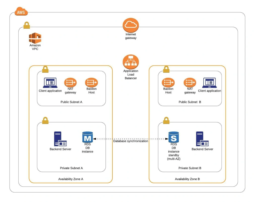
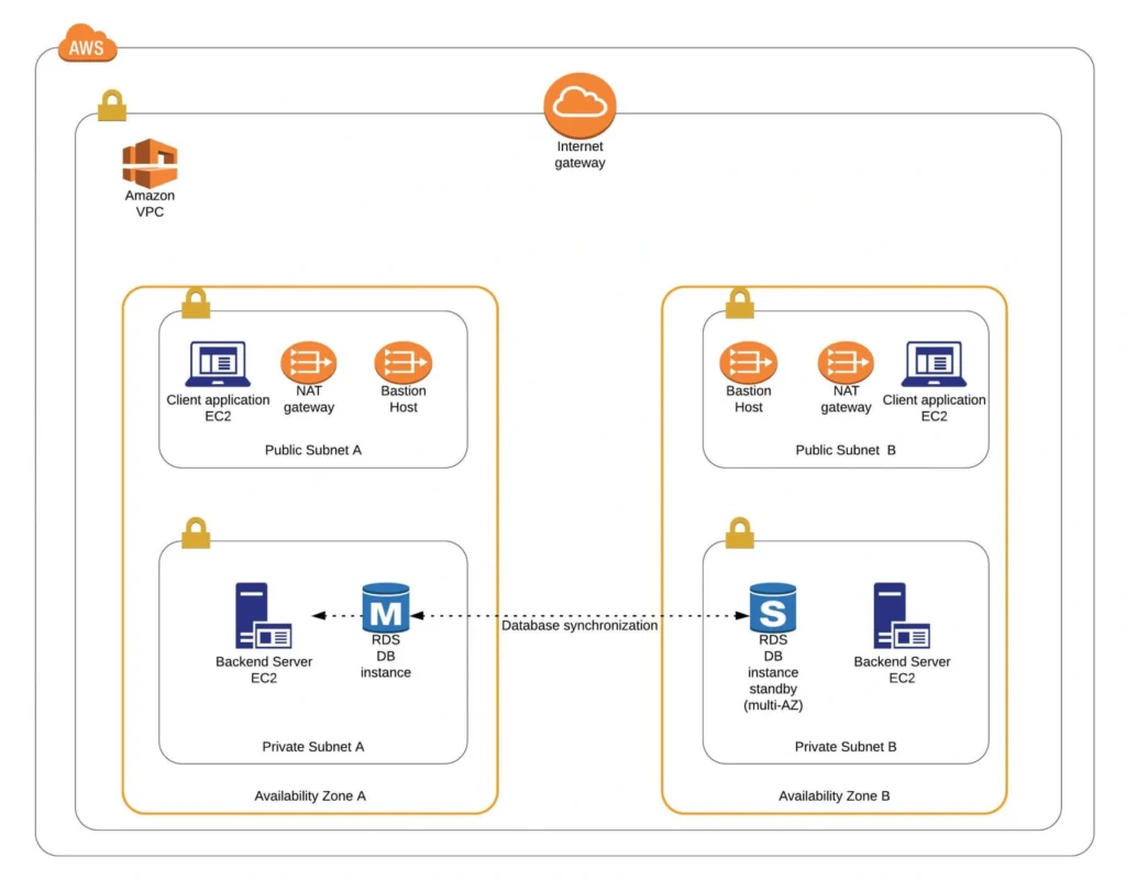
The diagram below presents our designed infrastructure. If you would like to learn more about design choices behind it, please read Part 1 - Architecture Scaffolding (VPC, Subnets, Elastic IP, NAT) . We have already created a VPC, subnets, NAT Gateways, and configured network routing. In this part of the series, we focus on the configuration of required EC2 instances, the creation of AMI images, setting up Bastion Hosts, and the RDS database.
AWS theory
1. Elastic cloud compute cloud (EC2)
Elastic Cloud Compute Cloud (EC2) is an Amazon service that allows you to manage your virtual computing environments, known as EC2 instances, on AWS. An EC2 instance is simply a virtual machine provisioned with a certain amount of resources such as CPU, memory, storage, and network capacity launched in a selected AWS region and availability zone. The elasticity of EC2 means that you can scale up or down resources easily, depending on your needs and requirements. The network security of your instances can be managed with the use of security groups by the configuration of protocols, ports, and IP addresses that your instances can communicate with.
There are five basic types of EC2 instances, which you can use based on your system requirements.
- General Purpose,
- Compute Optimized,
- Memory Optimized,
- Accelerated Computing,
- Storage Optimized.
In our infrastructure, we will use only general-purpose instances, but if you would like to learn more about different features of instance types, see the AWS documentation.
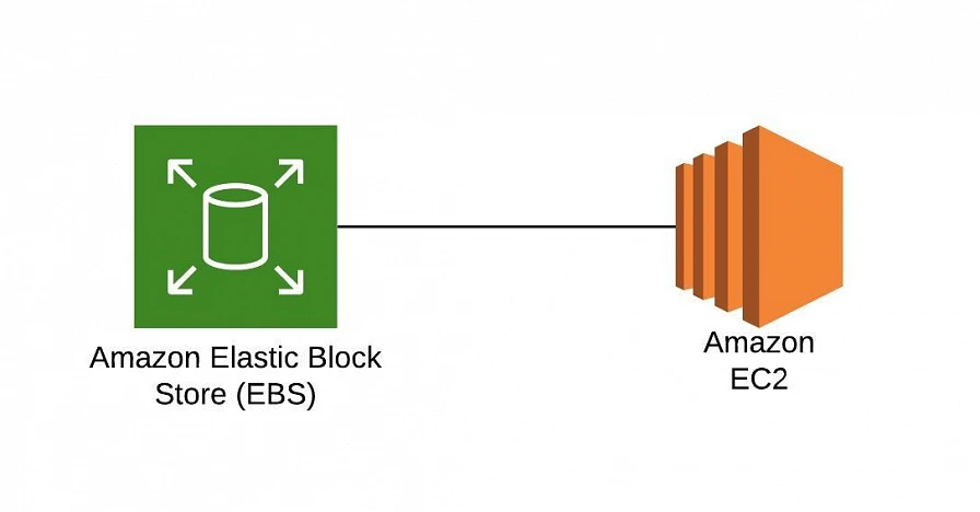
All EC2 instances come with instance store volumes for temporary data that is deleted whenever the instance is stopped or terminated, as well as with Elastic Block Store (EBS) , which is a persistent storage volume working independently of the EC2 instance itself.
2. Amazon Machine Images (AMI)
Amazon utilizes templates of software configurations, known as Amazon Machine Images (AMI) , in order to facilitate the creation of custom EC2 instances. AMIs are image templates that contain software such as operating systems, runtime environments, and actual applications that are used to launch EC2 instances. This allows us to preconfigure our AMIs and dynamically launch new instances on the go using this image instead of always setting up VM environments from scratch. Amazon provides some ready to use AMIs on the AWS Marketplace, which you can extend, customize, and save as your own (which we will do soon).
3. Key pair
Amazon provides a secure EC2 login mechanism with the use of public-key cryptography. During the instance boot time, the public key is put in an entry within ~/.ssh/authorized_keys , and then you can securely access your instance through SSH using a private key instead of a password. The public and private keys are known as a key pair.
4. IAM role
IAM means Identity and Access Management and it defines authentication and authorization rules for your system. IAM roles are IAM identities which comprise a set of permissions that control access to AWS services and can be attached to AWS resources such as users, applications, or services. As an example, if your application needs access to a specific AWS service such as an S3 Bucket, its EC2 instance needs to have a role with appropriate permission assigned.
5. Bastion Host
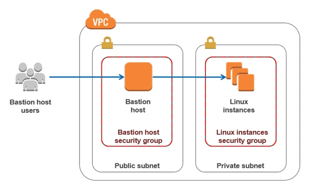
Bastion Host is a special purpose instance placed in a public subnet, which is used to allow access to instances located in private subnets while providing an increased level of security. It acts as a bridge between users and private instances, and due to its exposure to potential attacks, it is configured to withstand any penetration attempts. The private instances only expose their SSH ports to a bastion host, not allowing any direct connection. What is more, bastion hosts may be configured to log any activity providing additional security auditing.
6. Amazon Relational Database Service (RDS)
6.1. RDS
RDS is an Amazon service for the management of relational databases in the cloud. As of now (23.04.2020), it supports six database engines specifically Amazon Aurora, PostgreSQL, MySQL, MariaDB, Oracle Database, and SQL Server. It is easy to configure, scale and it provides high availability and reliability with the use of Read Replicas and Multi-AZ Deployment features.
6.2. Read replicas
RDS Read Replicas are asynchronous, read-only instances that are replicas of a primary “master” db instance. They can be used for handling queries that do not require any data change, thus reliving the workload from the master node.
6.3. Multi-AZ deployment
AWS Multi-AZ Deployment is an option to allow RDS to create a secondary, standby instance in a different AZ, and replicate it synchronously with the data from the master node. Both master and standby instances run on their own physically independent infrastructures, and only the primary instance can be accessed directly. The standby replica is used as a failover in case of any master’s failure, without changing the endpoint of your DB.
This reduces downtime of your system and makes it easier to perform version upgrades or create backup snapshots, as they can be done on the spare instance. Multi-AZ is usually used only on the master instance. However, it is also possible to create read replicas with Multi-AZ deployment, which results in a resilient disaster recovery infrastructure.
Practice
We have two applications that we would like to run on our AWS infrastructure. One is a Java 11 Spring Boot application, so the EC2 which will host it is required to have Java 11 installed. The second one is a React.js frontend application, which requires a virtual machine with a Node.js environment. Therefore, as the first step, we are going to set up a Bastion Host, which will allow us to ssh our instances. Then, we will launch and configure those two EC2 instances manually in the first availability zone. Later on, we will create AMIs based on those instances and use them for the creation of EC2s in the second availability zone.
1. Availability Zone A
1.1. Bastion Host
A Bastion Host is nothing more than a special-purpose EC2 instance. Hence, in order to create a Bastion Host, go into the AWS Management Console, and search for EC2 service. Then click the Launch Instance button, and you will be shown with an EC2 launch wizard. The first step is the selection of an AMI image for your instance. You can filter AMIs and select one based on your preferences. In this article, we will use the Amazon Linux 2 AMI (HVM), SSD Volume Type image.
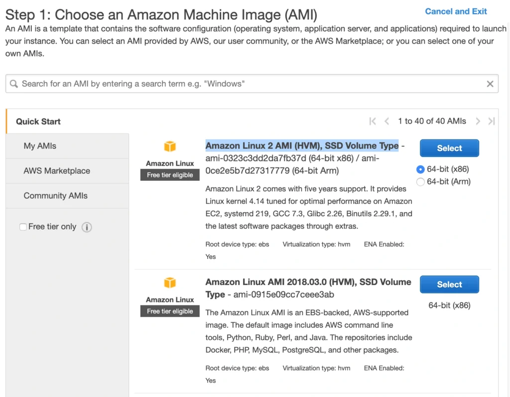
On the next screen, we need to choose an instance type for our image. Here, I am sticking with the AWS free tier program, so I will go with the general-purpose t2.micro type. Click Next: Configure instance Details . Here, we can define the number of instances, network settings, IAM configuration, etc. For now, let’s start with 1 instance, we will work on the scalability of our infrastructure later. In the Network section, choose your previously created VPC and public-subnet-a and enable Public IP auto-assignment. We do not need to specify any IAM role as we are not going to use any of the AWS services.
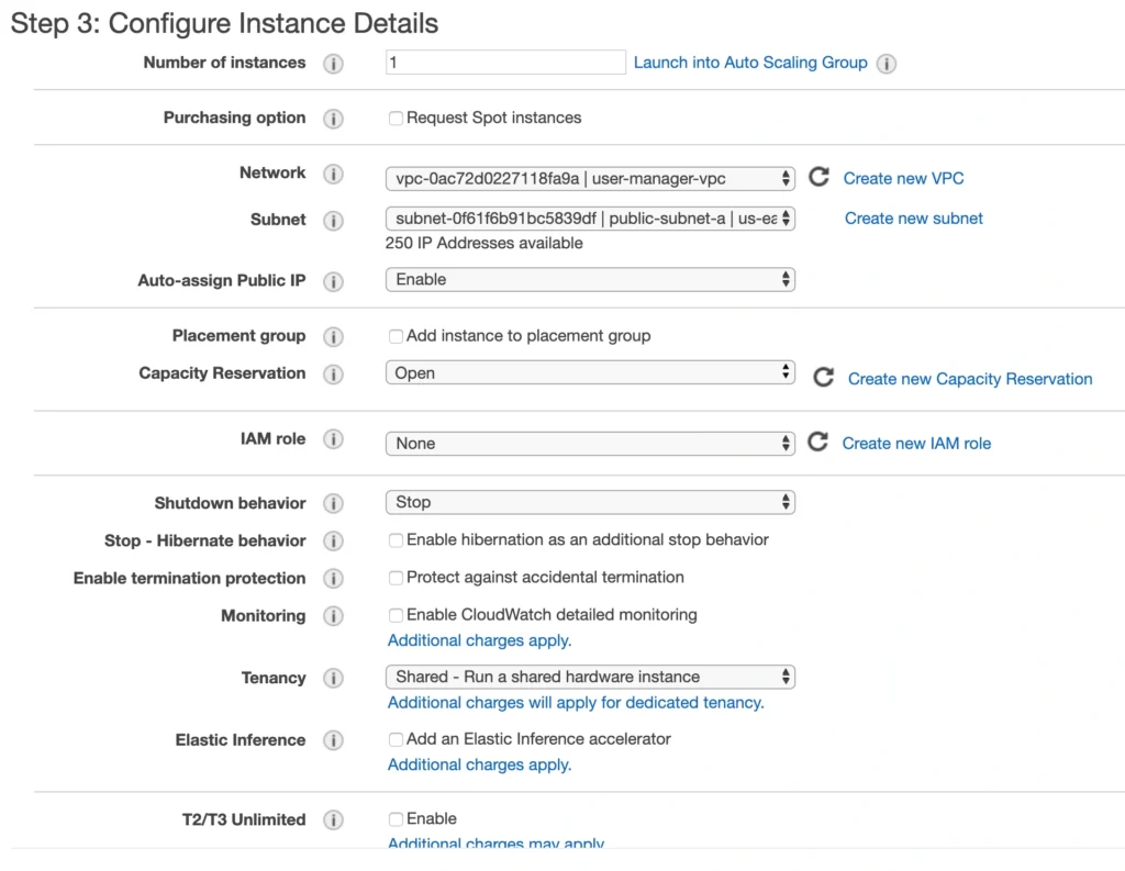
Click Next . Here you can see that the wizard automatically configures your instance with an 8GB EBS storage, which is enough for us. Click Next again. Now, we can add tags to improve the recognizability of our instance. Let’s add a Name tag bastion-a-ec2 . On the next screen, we can configure a security group for our instance. Create a new security group, name it bastion-sg .
You can see that there is already one predefined rule exposing our instance for SSH sessions from 0.0.0.0/0 (anywhere). You should change it here to allow only connections from your IP address. The important thing to note here is that in the production environment you would never expose your instances to the whole world, instead, you would whitelist the IP addresses of employees allowed to connect to your instance.
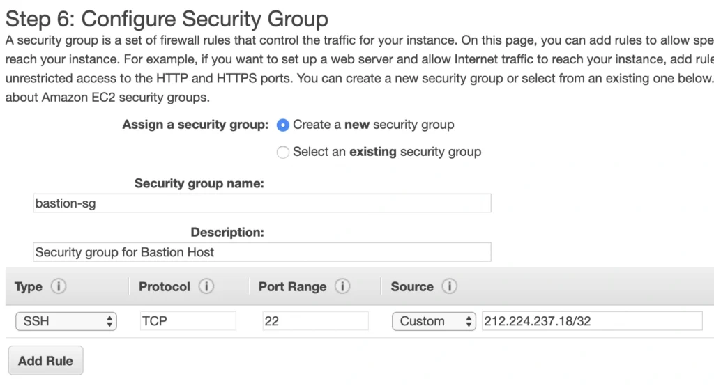
In the next step, you can review your EC2 configuration and launch it. The last action is the creation of a key pair. This is important because we need this key pair to ssh to our instance. Name the key pair e.g. user-manager-key-pair , download the private key, and store it locally on your machine. This is it, Amazon will take some time, but in the end, your EC2 instance will be launched.
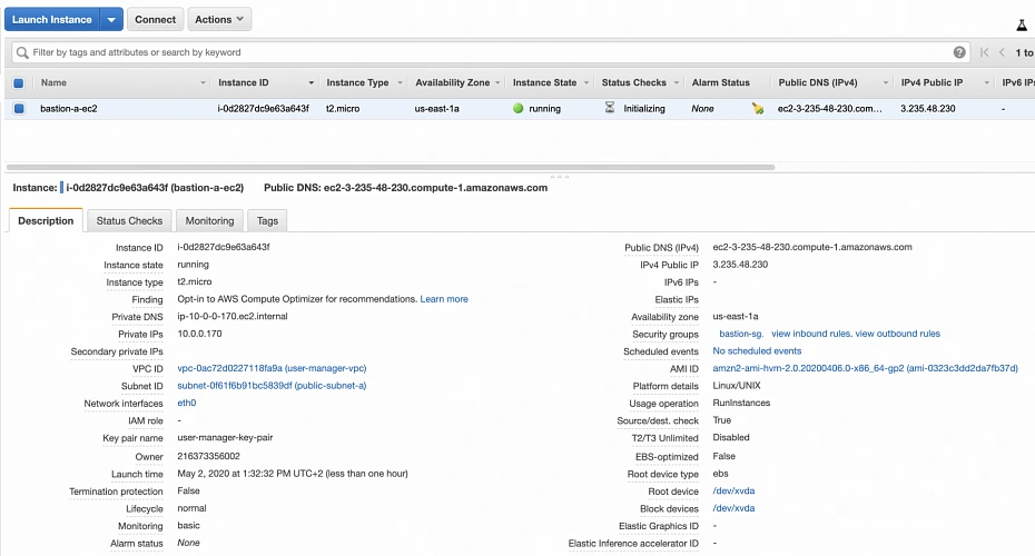
In the instance description section, you can find the public IP address of your instance. We can use it to ssh to the EC2. That is where we will need previously generated and hopefully locally saved private key (*.pem file). That’s it, our instance is ready for now. However, in production, it would be a good idea to harden the security of the Bastion Host even more. If you would like to learn more about that, we recommend this article .
1.2. Backend server EC2
Now, let’s create an instance for the backend server. Click Launch instance again, choose the same AMI image as before, place it in your user-manager-vpc, private-subnet-a, and do not enable public IP auto-assignment this time. Move through the next steps as before, add a server-a-ec2 name tag. In the security group configuration, create a new security group, and modify its settings to allow SSH incoming communication only from the bastion-sg .
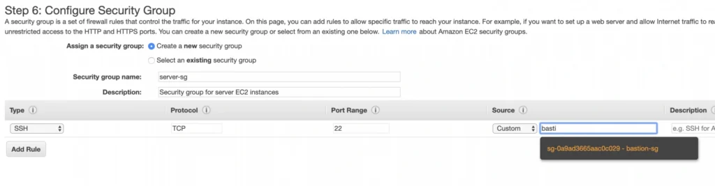
Launch the instance. You can create a new key pair or use the previously created one (for simplicity I recommend using the same key pair for all instances). In the end, you should have your second instance up and running.
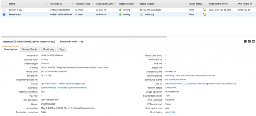
You can see that server-a-ec2 does not have any public IP address. However, we can access it through the bastion host. First, we need to add our key to a keychain and then we can ssh to our bastion host instance adding -A flag to the ssh command. This flag enables agent-forwarding, which will let you ssh into your private instance without explicitly specifying private key again. This is a recommended way, which lets you avoid storage of the private key on the bastion host instance which could lead to a security breach.
ssh-add -k
ssh -A -i path-to-your-pem-file ec2-user@bastion-a-ec2-instance-public-ip
Then, inside your bastion host execute the command:
ssh ec2-user@server-a-ec2-instance-private-ip
Now, you should be inside your server-a-ec2 private instance. Let’s install the required software on the machine by executing those commands:
sudo yum update -y &&
sudo amazon-linux-extras enable corretto8 &&
sudo yum clean metadata &&
sudo yum install java-11-amazon-corretto &&
java --version
As a result, you should have java 11 installed on your server-a-ec2 instance. You can go back to the local command prompt by executing the exit command twice.
AMI
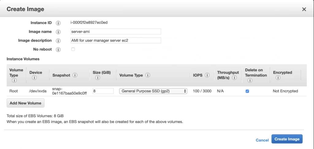
The ec2 instance for the backend server is ready for the deployment. In the second availability zone, we could follow exactly the same steps. However, there is an easier way. We can create an AMI image based on our pre-configured instance and use it later for the creation of the corresponding instance in availability zone b. In order to do that, go again into the Instances menu, select your instance, click Actions -> Image -> Create image . Your AMI image will be created and you will be able to find it in the Images/AMIs section.
1.3. Client application EC2
The last EC2 instance we need in the Availability Zone A will host the client application. So, let’s go once again through the process of EC2 creation. Launch instance, select the same base AMI as before, select your VPC, place the instance in the public-subnet-a , and enable public IP assignment. Then, add a client-a-ec2 Name tag, and create a new security group client-sg allowing SSH incoming connection from the bastion-sg security group. That’s it, launch it.
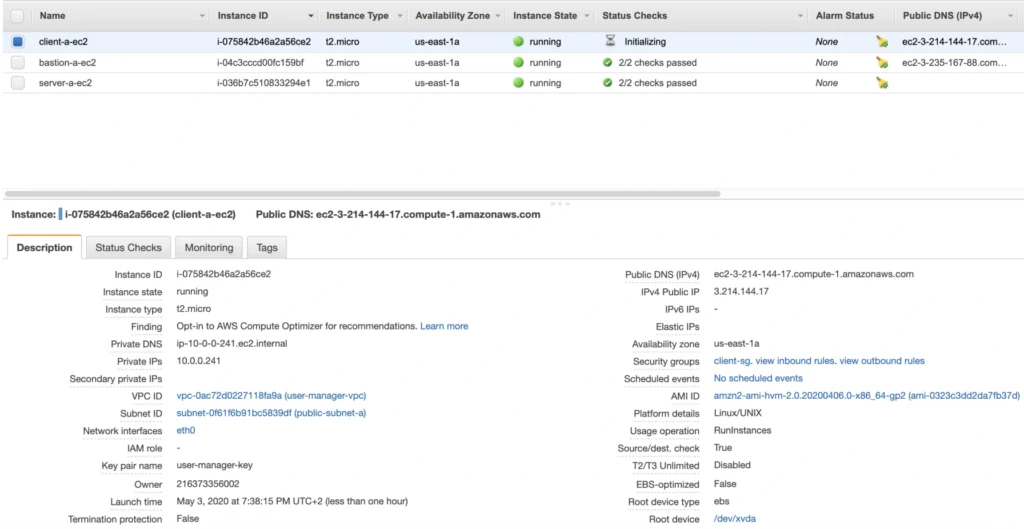
Now, SSH to the instance through the bastion host, and install the required software.
ssh -A -i path-to-your-pem-file ec2-user@bastion-a-ec2-instance-public-ip
Then, inside your bastion host execute the command:
ssh -A -i path-to-your-pem-file ec2-user@bastion-a-ec2-instance-public-ip
Inside client-a-ec2 command prompt, execute :
sudo yum update &&
curl -sL https://rpm.nodesource.com/setup_12.x | sudo bash - &&
sudo yum install -y nodejs &&
node -v &&
npm -v
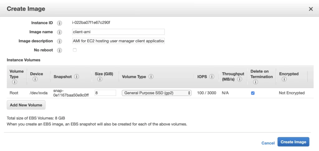
Exit the EC2 command prompt and create a new AMI image based on it.
2. Availability Zone B
2.1. Bastion Host
Create the second bastion host instance following the same steps as for availability zone a, but this time place it in public-subnet-b , add Name tag bastion-b-ec2 , and assign to it previously created bastion-sg security group.
2.2. Backend server EC2
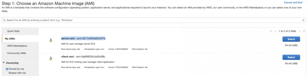
For the backend server EC2, go again to the Launch Instance menu, and this time instead of using Amazon’s AMI switch to My AMI’s tab and select the previously created server-ami image. Place the instance in the private-subnet-b , add a name tag server-b-ec2 , and assign to it the server-sg security group.
2.3. Client application EC2
Just as for the backend server instance, launch the client-b-ec2 using your custom AMI image. This time select the client-ami image, place EC2 in the public-subnet-b , enable automatic IP assignment, and choose the client-sg security group.
3. RDS
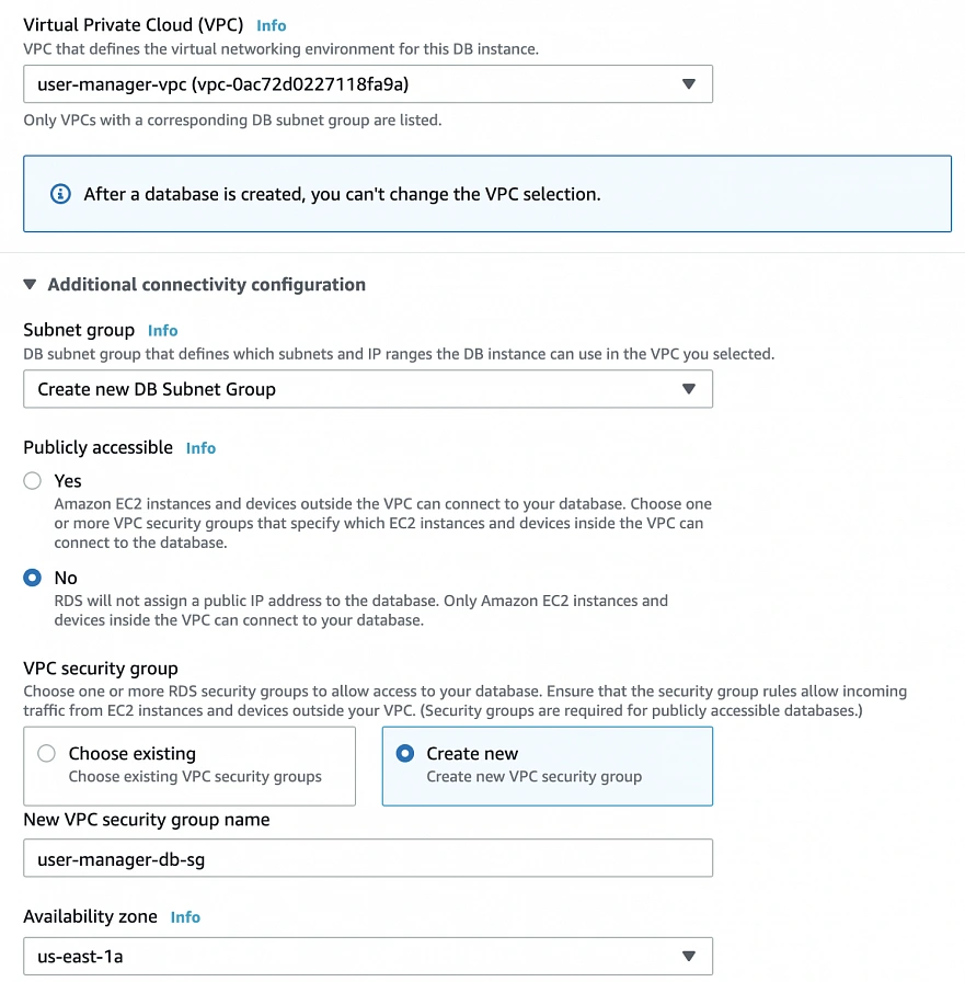
We have all our EC2 instances ready. The last part which we will cover in this article is the configuration of RDS. For that, go into the RDS service in the AWS Management Console and click Create database. In the database configuration window, follow the standard configuration path. Select MySQL db engine, and select Free tier template. Set your db name as user-manager-db , specify master username and password, select your user-manager-vpc , availability zone a, and make the database publicly not accessible. Create also a new user-manager-db-sg security group.
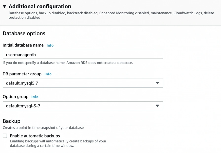
In the Additional configuration section, specify the initial db name, and finally create a database.
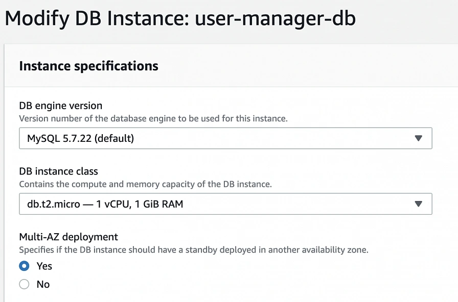
After AWS finishes the creation process, you will be able to get the database endpoint, which we will use to connect to the database from our application later on. Now, in order to provide high availability of the database, click the Modify button on the created database screen, and enable Multi-AZ deployment. Please, bear in mind that Multi-AZ deployment is not included in the free tier program, so if you would like to avoid any charges, skip this point.
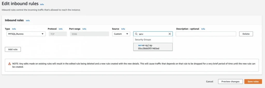
As the last step, we need to add a rule to the user-manager-db-sg to allow incoming connections from our server-sg on port 3306 in order to allow communication between our server and the database.
EC2, AMI, Bastion Host, RDS - Summary
Congratulations, our infrastructure is almost ready for deployment. As you can see in our final diagram, the only thing which is missing is the load balancer. In the next part of the series, we will take care of that, and deploy our applications to have a fully functioning system running on AWS infrastructure!
Sources:
- https://cloudacademy.com/blog/aws-bastion-host-nat-instances-vpc-peering-security/
- https://aws.amazon.com/quickstart/architecture/linux-bastion/
- https://aws.amazon.com/blogs/security/securely-connect-to-linux-instances-running-in-a-private-amazon-vpc/
- https://app.pluralsight.com/library/courses/aws-developer-getting-started/table-of-contents
- https://app.pluralsight.com/library/courses/aws-developer-designing-developing/table-of-contents
- https://app.pluralsight.com/library/courses/aws-networking-deep-dive-vpc/table-of-contents
- https://www.techradar.com/news/what-is-amazon-rds
- https://medium.com/kaodim-engineering/hardening-ssh-using-aws-bastion-and-mfa-45d491288872
- https://cloudacademy.com/blog/aws-bastion-host-nat-instances-vpc-peering-security/
- https://docs.aws.amazon.com/IAM/latest/UserGuide/id_roles.html
- https://docs.aws.amazon.com/AWSEC2/latest/UserGuide/ec2-key-pairs.html
- https://aws.amazon.com/ec2/instance-types/
- https://docs.aws.amazon.com/AWSEC2/latest/UserGuide/concepts.html

The path towards enterprise level AWS infrastructure – architecture scaffolding
This article is the first one of the mini-series which will walk you through the process of creating an enterprise-level AWS infrastructure. By the end of this series, we will have created an infrastructure comprising a VPC with four subnets in two different availability zones with a client application, backend server, and a database deployed inside. Our architecture will be able to provide scalability and availability required by modern cloud systems. Along the way, we will explain the basic concepts and components of the Amazon Web Services platform. In this article, we will talk about the scaffolding of our architecture to be specific a Virtual Private Cloud (VPC), Subnets, Elastic IP Addresses, NAT gateways, and route tables. The whole series comprises of:
- Part 1 - Architecture Scaffolding (VPC, Subnets, Elastic IP, NAT)
- Part 2 - The Path Towards Enterprise Level AWS Infrastructure – EC2, AMI, Bastion Host, RDS
- Part 3 - Load Balancing and Application Deployment (Elastic Load Balancer)
The cloud, as once explained in the Silicon Valley tv-series, is “this tiny little area which is becoming super important and in many ways is the future of computing.” This would be accurate, except for the fact that it is not so tiny and the future is now. So let’s delve into the universe of cloud computing and learn how to build highly available, secure and fault-tolerant cloud systems, how to utilize the AWS platform for that, what are its key components and how to deploy your applications on AWS.
Cloud computing
Over the last years, the IT industry underwent a major transformation in which most of the global enterprises moved away from their traditional IT infrastructures towards the cloud. The main reason behind that is the flexibility and scalability which comes with cloud computing, understood as provisioning of computing services such as servers, storage, databases, networking, analytic services, etc. over the Internet ( the cloud ). In this model organizations only pay for the cloud resources they are actually using and do not need to manage the physical infrastructure behind it. There are many cloud platform providers on the market with the major players being Amazon Web Services (AWS), Microsoft Azure and Google Cloud. This article focuses on services available on AWS, but bear in mind that most of the concepts explained here will have their equivalents on the other platforms.
Infrastructure overview
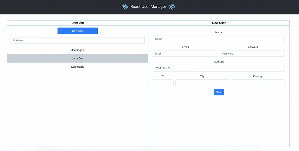
Let’s start with what we will build throughout this series. The goal is to create a real-life, enterprise-level AWS infrastructure that will be able to host a user management system consisting of a React.js web application, Java Spring Boot server and a relational database.
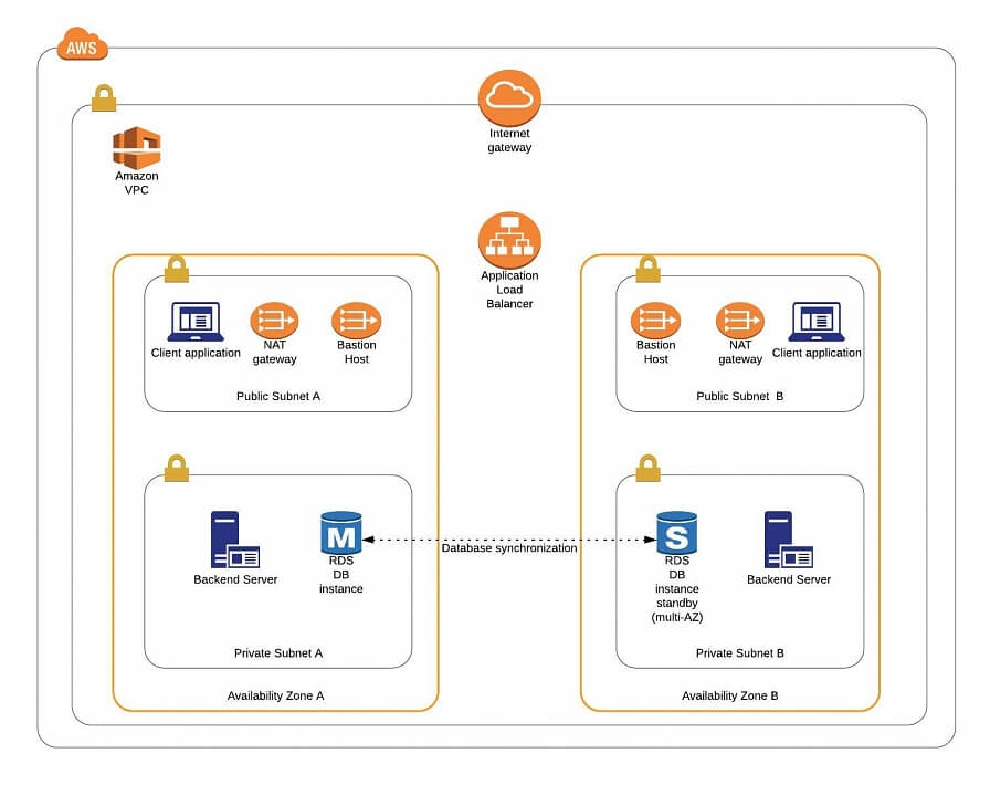
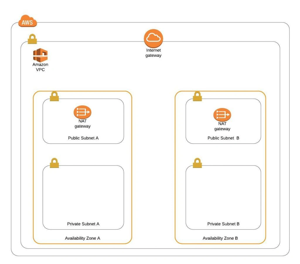
The architecture diagram is shown in figure 1. It comprises a VPC with four subnets (2 public and 2 private) distributed across two different availability zones. In public subnets are hosted a client application, a NAT gateway and a Bastion Host (more on that later), while our private subnets contain backend server and database instances. The infrastructure also includes Internet Gateway to enable access to the Internet from our VPC and a Load Balancer. The reasoning behind placing the backend server and database in private subnets is to protect those instances from being directly exposed to the Internet as they may contain sensitive data. Instead, they will only have private IP addresses and be behind a NAT gateway and a public-facing Elastic Load Balancer. Presented infrastructure provides a high level of scalability and availability through the introduction of redundancy with instances deployed in two different availability zones and the use of auto-scaling groups which provide automatic scaling and health management of the system.
Figure 2 presents the view of the user management web application system we will host on AWS:
The applications can be found on GitHub.
In this part of the article series, we will focus on the scaffolding of the infrastructure, namely allocating elastic IP addresses, setting up the VPC, creating the subnets, configuring NAT gateways and route tables.
AWS Free Tier Note
AWS provides its new users with a 12-month free tier, which gives customers the ability to use their services up to specified limits free of charge. Those limits include 750 hours per month of t2.micro size EC2 instances, 5GB of Amazon S3 storage, 750 hours of Amazon RDS per month, and much more. In the AWS Management Console, Amazon usually provides indicators in which resource choices are part of the free tier, and throughout this series, we will stick to those. If you want to be sure you will not exceed the free tier limits, remember to stop your EC2 and RDS instances whenever you finish working on AWS. You can also set up a billing alert that will notify you if you exceed the specified limit.
AWS theory
1. VPC
The first step of our journey into the wide world of the AWS infrastructure is getting to know Amazon Virtual Private Cloud (VPC). VPC allows developers to create a virtual network in which they can launch resources and have them logically isolated from other VPCs and the outside world. Within the VPC your resources have private IP addresses with which they can communicate with one another. You can control the access to all those resources inside the VPC and route outgoing traffic as you like.
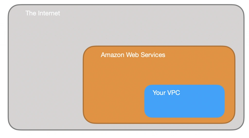
Access to the VPC is configured with the use of several key structures:
Security groups - They basically work like mini firewalls defining allowed incoming and outgoing IP addresses and ports. They can be attached at the instance level, be shared among many instances and provide the possibility to allow access from other security groups instead of IPs.
Routing tables - Routing tables are responsible for determining where the network traffic from a subnet or gateway should be directed. There is a main route table associated with your VPC, and you can define custom routing tables for your subnets and gateways.
Network Access Control List (Network ACL) - It acts as an IP filtering table for incoming and outgoing traffic and can be used as an additional security layer on top of security groups. Network ACLs act similarly to the security groups, but instead of applying rules on the instance level, they apply them to the entire VPC or subnet.
2. Subnets
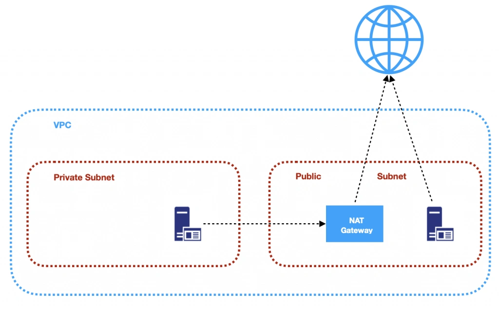
Instances cannot be launched directly into a VPC. They need to live inside subnets. A Subnet is an additional isolated area that has its own CIDR block, routing table, and Network Access Control List. Subnets allow you to create different behaviors in the same VPC. For instance, you can create a public subnet that can be accessed and have access to the public internet and a private subnet that is not accessible through the Internet and must go through a NAT (Network Address Translation) gateway in order to access the outside world.
3. NAT (Network Address Transfer) gateway
NAT Gateways are used in order to enable instances located in private subnets to connect to the Internet or other AWS services, while still preventing direct connections from the Internet to those instances. NAT may be useful for example when you need to install or upgrade software or OS on EC2 instances running in private subnets. AWS provides a NAT gateway managed service which requires very little administrative effort. We will use it while setting up our infrastructure.
4. Elastic IP
AWS provides a concept of Elastic IP Address which is used to facilitate the management of dynamic cloud computing. Elastic IP Address is a public, static IP Address that is associated with your AWS account and can be easily allocated to one of your EC2 instances. The idea behind it is that the address is not strongly associated with your instance but instead elasticity of the address allows in a case of any failure in the system to swiftly remap the address to another healthy instance in your account.
5. AWS Region
AWS Regions are geographical areas in which AWS has data centers. Regions are divided into Availability Zones (AZ) which are independent data centers placed relatively close to each other. Availability Zones are used to provide redundancy and data replication. The choice of AWS region for your infrastructure should be determined to take into account factors such as:
- Proximity - you would usually want your application to be deployed close to your region of operation for latency or regulatory reasons.
- Cost - different regions come with different pricing.
- Feature selection - not all services are available in all regions, this is especially the case for newly introduced features.
- Several availability zones - all regions have at least 2 AZ, but some of them have more. Depending on your needs, this may be a key factor.
Practice
AWS Region
Let’s commence with a selection of the AWS region to operate in. In the top right corner of the AWS Management Console, you can choose a region. At this point, it does not really matter which region you choose (as discussed earlier, it may for your organization). However, it is important to note that you will always only view resources launched in the currently selected region.
Elastic IP
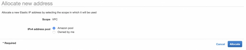
The next step is the allocation of an elastic IP address. For that purpose, go into the AWS Management console, and find the VPC service. In the left menu bar, under the Virtual Private Cloud section, you should see the Elastic IPs link. There you can allocate a new address owned by yourself or from the pool of Amazon’s available addresses.
Availability Zone A configuration
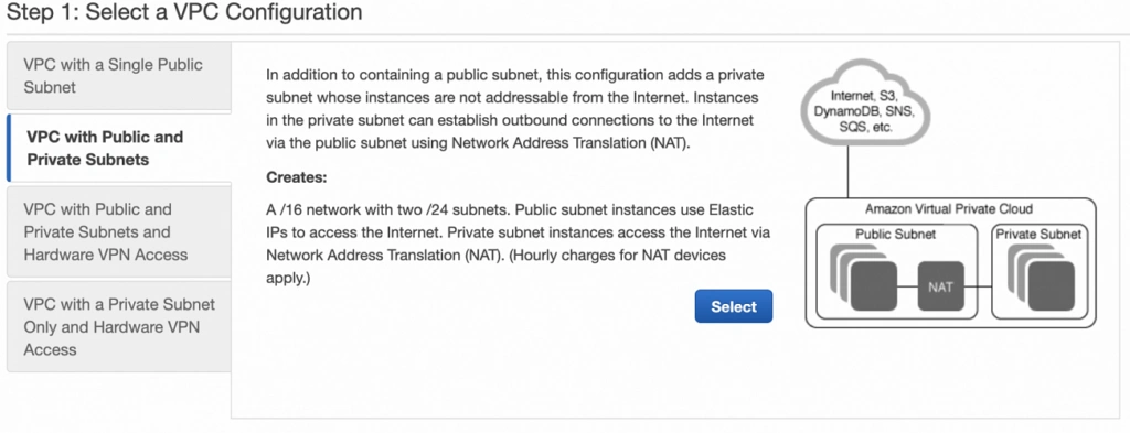
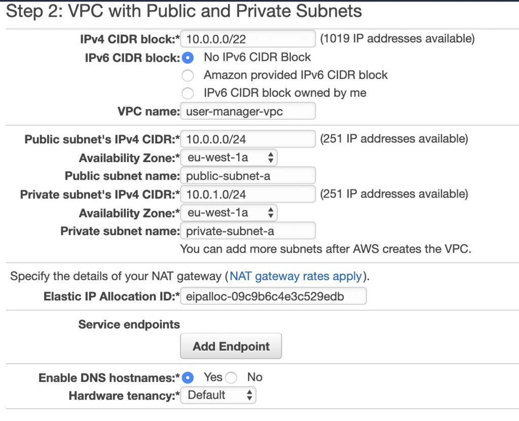
Next, let’s create our VPC and subnets. For now, we are going to set up only Availability Zone A and we will work on High Availability after the creation of the VPC. So go again into the VPC service dashboard and click the Launch VPC Wizard button. You will be taken to the screen where you can choose what kind of a VPC configuration you want Amazon to set you up with. In order to match our target architecture as closely as possible, we are going to choose VPC with Public and Private Subnets .
The next screen allows you to set up your VPC configuration details such as:
- name,
- CIDR block,
- details of the subnets:
- name,
- IP address range - a subset of the VPC CIDR range,
- availability zone,
As shown in the architecture diagram (fig. 1), we need 4 subnets in 2 different availability zones. So let’s set our VPC CIDR to 10.0.0.0/22, and have our subnets as follows:
- public-subnet-a: 10.0.0.0/24 (zone A)
- private-subnet-a: 10.0.1.0/24 (zone A)
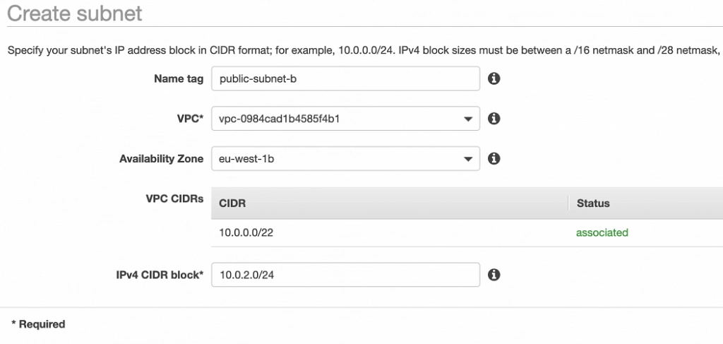
- public-subnet-b: 10.0.2.0/24 (zone B)
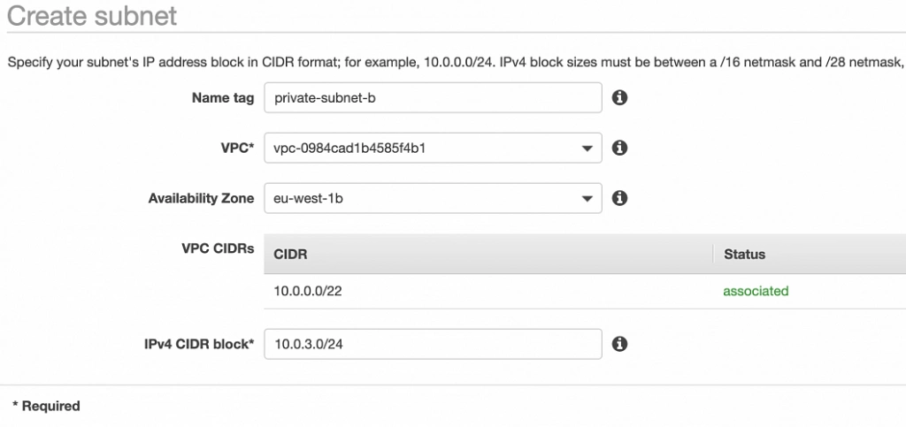
- private-subnet-b: 10.0.3.0/24 (zone B)
Set everything up as shown in figure 7. The important aspects to note here are the choice of the same availability zone for public and private subnets, and the fact that Amazon will automatically set us up with a NAT gateway for which we just need to specify our previously allocated Elastic IP Address. Now, click the Create VPC button, and Amazon will configure your VPC.
NAT gateway
When the creation of the VPC is over, go to the NAT Gateways section, and you should see the gateway created for you by AWS. To make it more recognizable, let us edit its Name tag to nat-a .

Route tables
Amazon also configured Route Tables for your VPC. Go to the Route Tables section, and you should have there two route tables associated with your VPC. One of them is the main route table of your VPC, and the second one is currently associated with your public-subnet-a. We will modify that setting a bit.
First, select the main route table, go to the routes tab and click Edit routes . There are currently two entries. The first one means Any IP address referencing local VPC CIDR should resolve locally and we shouldn’t modify it. The second one is pointing to the NAT gateway, but we will change it to configure the Internet Gateway of our VPC in order to let outgoing traffic reach the outside world.

Next, go to the Subnet Associations tab and associate the main route table with public-subnet-a. You can also edit its Name tag to main-rt . Then, select the second route table associated with your VPC, edit its routes to route every outgoing Internet request to the nat-a gateway as shown in figure 10. Associate this route table with private-subnet-a and edit its Name tag to private-a-rt .

Availability Zone B Configuration
Well done, availability zone A is configured. In order to provide High Availability, we need to set everything up in the second availability zone as well. The first step is the creation of the subnets. Go again to a VPC dashboard in the AWS management console and in the left menu bar find the Subnets section. Now, click the Create subnet button and configure everything as shown in figures 11 and 12.
public-subnet-b
private-subnet-b
NAT gateway
For availability zone B we need to create the NAT gateway manually. For that, find the NAT Gateways section in the left menu bar of the VPC dashboard, and click Create NAT Gateway . Select public-subnet-b , allocate EIP and add a Name tag with value nat-b .
Route tables
The last step is the configuration of the route tables for the subnets in availability zone B. For that, go to the Route Tables section again. Our public-subnet-b is going to have the same routing rules as the public-subnet-a, so let’s add a new association to our main-rt table for public-subnet-b. Then, click the Create route table button, name it private-b-rt , choose our VPC and click create . Next, select the newly created table go to the Routes tab and Edit routes by analogy with the private-a-rt table, but instead of directing every outside going request to nat-a gateway route it to nat-b (fig. 13).

In the end, you should have three route tables associated with your VPC as shown in figure 14.

Summary
That’s it, the scaffolding of our VPC is ready. The diagram shown in fig.15 presents a view of the created infrastructure. It is now ready for the creation of required EC2 instances, Bastion Hosts, configuration of an RDS database and deployment of our applications, which we will do in the next part of the series .
Sources:
- https://azure.microsoft.com/en-us/overview/what-is-cloud-computing/
- https://aws.amazon.com/what-is-aws/
- https://docs.aws.amazon.com/AWSEC2/latest/UserGuide/elastic-ip-addresses-eip.html
- https://docs.aws.amazon.com/vpc/latest/userguide/VPC_Route_Tables.html
- https://docs.aws.amazon.com/vpc/latest/userguide/VPC_SecurityGroups.html#DefaultSecurityGroup
- https://docs.aws.amazon.com/vpc/latest/userguide/vpc-network-acls.html
- https://medium.com/@datapath_io/elastic-ip-static-ip-public-ip-whats-the-difference-8e36ac92b8e7
- https://cloudacademy.com/blog/aws-bastion-host-nat-instances-vpc-peering-security/
- https://aws.amazon.com/blogs/aws/internal-elastic-load-balancers/
- https://aws.amazon.com/quickstart/architecture/linux-bastion/
- https://aws.amazon.com/blogs/security/securely-connect-to-linux-instances-running-in-a-private-amazon-vpc/
- http://thebluenode.com/exposing-private-ec2-instances-behind-public-elastic-load-balancer-elb-aws
- https://app.pluralsight.com/library/courses/aws-developer-getting-started/table-of-contents
- https://app.pluralsight.com/library/courses/aws-developer-designing-developing/table-of-contents
- https://app.pluralsight.com/library/courses/aws-networking-deep-dive-vpc/table-of-contents
- https://datanextsolutions.com/blog/using-nat-gateways-in-aws/
- https://docs.aws.amazon.com/vpc/latest/userguide/vpc-nat-gateway.html
How to ensure business continuity and workplace readiness in case of unexpected events
While the ongoing COVID-19 outbreak is affecting millions of people and causing numerous disruptions to the global economy, technology companies can undertake significant steps to assure business continuity for their employees and stakeholders. This demanding period is also a validation of company policies and may lead to continuous changes in the way we work and run projects.
When the whole world stops to narrow down the spread of COVID-19 and various industries suffer due to the lockdown, the technology companies should focus on providing its services in order to help those who are on the front line of the crisis and help the global economy recover to avoid unpleasant consequences of the pandemic. Now is the time that verifies strategies and preparation for working entirely in a remote mode, often without physical access to the office buildings, and at the same time delivering services at the highest level.
We share with you what we have done to prepare for the situation when our entire team has to work remotely and deliver services for companies located globally. We asked several of our colleagues - from IT and people operations to project managers and developers - how they contributed to business continuity planning and what it is like to work from home these days. And while the outbreak is a serious danger, we have to learn from the entire situation and do the homework to minimize issues in the future as no one can guarantee that something similar won't happen again.
Providing a toolset, remote access, and office coordination while the entire team is distributed
The last three weeks have shown that agile companies, building distributed teams, and using cloud technologies with distant access to proper tools are able to adjust to the fully remote model of work much easier. The current emergency cut down the numerous discussions questioning the necessity of moving enterprises to the cloud, providing employees with mobile workstations, planning scenarios anticipating a period when a company has to operate independently without physical access to the infrastructure located in headquarters. Those of businesses that have embraced that strategic business continuity plan avoided chaotic operations and distractions in service delivery.
Here we dive into the list of things necessary to guarantee the business going forward:
As a fully equipped workstation that enables employees to work effectively and focus on their tasks seems obvious, it becomes more critical where you have to back up developers and designers with highly performing devices needed to run more sophisticated software. So whenever you are planning your purchasing, take into account that the devices you’re buying may have to be used for weeks in domestic conditions.
To make sure that members of your team can smoothly move to remote work and communicate flawlessly with their peers and your customers, you should use tools accelerating collaboration and simplifying access to other people. Our typical tool gear consists of Slack, Zoom, Dropbox, Office 365 - including remote access to the mailbox, and Jira. It can be developed accordingly to a given team's needs.
Nowadays, we have to prepare to onboard and gear up our employees remotely. How does it work at Grape Up? We send a full package that consists of a laptop with the entire system configured and equipped with access to VPN and tools needed to start the job, headphones, a monitor, a keyboard.
VPN is now obligatory in order to allow everyone at the company to use databases, internal systems, network drives, and knowledge management platforms. As many people need flexibility in access to these resources, it’s highly recommended to use VPN on a daily basis, verify how it works and avoid thinking about it as something needed only in emergency circumstances - since now it’s a new normal. Among other important advantages, VPN helps your company with security, under the condition you manage access properly and monitor in case of any tries of attack.
Current circumstances and uncertainty may lead to growth in scams and phishing. And while VPN and used technologies increase our safety, we have to remember that proper communication can enhance security even more. It’s your job to make everyone aware of what they may face and how to treat it.
To sum up, in order to ensure that your business operations and service delivery perform impeccably in case of emergency you are obligated to prepare your company to work without physical access to your headquarters. It’s also fundamental to protect your business with the right backups in case of the worst scenarios.
And here appears one of the most challenging things - a human factor - make sure that your firm applied the right policy that tears down silos and assure that in case someone is unreachable or in emergence that there is a person with knowledge and accesses that can substitute that role.
Office management in a remote mode
How shifting to work from home impacts office management? In modern and agile organizations office coordination is often done remotely as many teams run projects in various locations. A situation like this happening right now shows that it is essential to build solutions that mean to provide your employees with mobile and flexible workstations. Being responsible for office management in a time of going fully remote means ensuring that every workspace is safe and well protected in case of any fraud trying to take advantage of the demanding circumstances.
By coordinating all the supplies and reducing things that are not needed when the whole team won’t be on-site for an unknown period of time, a company can gain some impressive cost savings. It is also important to have a plan to make all your workplaces ready to be opened when the situation changes so your employees could easily get back on the right track.
People operations, continuous engagement and remote learning
Security and taking care of the entire team is the number one priority. In business that can be easily run remotely, working from home is the best-case scenario. Companies that create a culture that empowers people to work independently, values open communication through various channels and encourages to be engaged even while the conditions are challenging, can avoid distraction in services.
How do we do it at Grape Up? Our company's culture is built on openness and collaboration - we value our weekly Lunch & Learn sessions designed to grow together and share some time on building relationships. The key here comes to thinking about it as a long-term process, no as a scenario for a demanding time.
While working remotely and willing to develop their skills, employees need well-documented resources - internal wiki, tutorials, guides, and knowledgebases. We at Grape Up promote learning by dealing with real problems together and the approach “try and I will assist you” over “I will tell you how to do it”. Our people continue helping each other in skills development, even when pair programming is done from distance.
Key to business continuity - service delivery management
Project managers, Product Owners, Scrum Masters and Service Delivery Managers play a vital role in providing business continuity and ensuring that customers are satisfied with the services, projects develop in the right direction, and the whole team is engaged yet have all the tools to work comfortably.
According to leaders of our project teams, their job, more than ever, comes to making sure that everyone is on the same page. How do they achieve it? By simplifying communication. Following the progress and letting everyone know how things stand during daily calls help to sustain engagement and chase common goals. But it's also important to do it carefully - spending a visible part of a day on calls and video meetings may lead to the opposite effect.
So when many things are similar to the typical working routine, what has changed? Pair programming is quite challenging now. To deal with it, we have worked out some kind of trade-off; half of a day work in pairs (of course remotely) and the second part by themselves.
What is often emphasized by our management team; the situation requires more empathy and understanding both for customers and colleagues. Many people feel confused and some may be affected or feel overwhelmed - it’s extremely important to be honest, informing about possible obstacles and inconveniences to improve what is possible and anticipate potential difficulties.
Coding from home
Working from home and being responsible for providing services that are crucial for many companies to exist, is nothing new to the development teams. What do they need to focus on building solutions that empower the entire industry to move forward?
First of all - a company that intends to perform well in a remote, distributed mode has to start with creating a culture that supports collaborative relationships between members of the projects and representatives of a customer. Understanding, trust, and open communication are the credentials of every fruitful cooperation. It’s extremely valuable when you cannot work face to face and take some time to get to know each other in a typical environment.
This leads us to the second thing - engagement. Teams that value creativity and encourage people to care about projects and motivate others to be active in chasing project goals can achieve impressive results even if the circumstances are difficult and communication among members is limited to the online channels.
In terms of the highly demanding situations, being responsive and always open to help your customers, both with planned tasks and with extraordinary issues, is something that builds a special bond and gives your business partners confidence that you assist their teams even when things are getting worse.
While working remotely, communication that enables asking questions and diving into some complicated topics is the most effective way to avoid misunderstanding, especially when it comes to task requirements and problem analysis. The role of a company leader should be focused on building a culture that supports dialogue and transparency - it has never been more important to talk about challenges, faced issues, and daily work. Every member of a team can help with making work more effective when sharing their experiences.
Along with the set of tools described above, the development teams can utilize two extremely useful apps; Pointing poker - browser extension to estimate task performance and Mural to create a table of good and bad experience during a retrospective.
It’s time for agile companies to provide business continuity and help the global economy recover
By moving to a remote work mode we can all help our authorities in fighting with the spread of COVID-19. The safety of employees and their families is a priority for the enterprises that feel responsible for people who build their organizations. This crisis reshapes the global economy and affects numerous industries. Agile companies that are designed to easily adjust to the changing conditions and can provide business continuity during difficult times, empower their partners to mitigate the struggles and recover.

The state of Kubernetes - what upcoming months will bring for the container orchestration
Kubernetes has become a must-have container orchestration platform for every company that aims to gain a competitive advantage by delivering high-quality software at a rapid pace. What’s the state of Kubernetes at the beginning of 2020? Is there room for improvement? Here is a list of trends that should shape the first months of the upcoming year.
As a team that provides own Multicloud Enterprise Kubernetes platform and empowers numerous companies in adopting K8s, we follow all the news that helps to prepare for the upcoming trends in using this cloud-native platform. And there are the best places to learn what’s new and what’s coming like KubeCon I CloudNativeCon conferences.
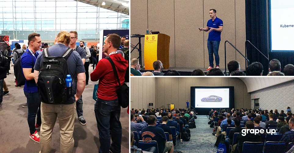
A few weeks ago, San Diego hosted KubeCon + CloudNativeCon North America gathering 12 thousand cloud-native enthusiasts - 50% increase in the number of attendees in comparison to the previous edition shows the scale of the Kubernetes' popularity growth. During the event, we had a chance to listen about new trends and discuss further opportunities with industry experts. Most of the news announced in San Diego will influence the upcoming months in a cloud-native world. Below, we focus on the most important ones.
Kubernetes is a must for the most competitive brands
What makes KubeCon so likable? Access to Kubernetes experts, networking with an amazing community of people gathered around CNCF, chance to learn the trends before they become mainstream? For sure, but what also makes it so special? The answer comes to the hottest brands that join cloud-native nation these days - Pinterest, Home Depot, Walmart, Tinder and many more.
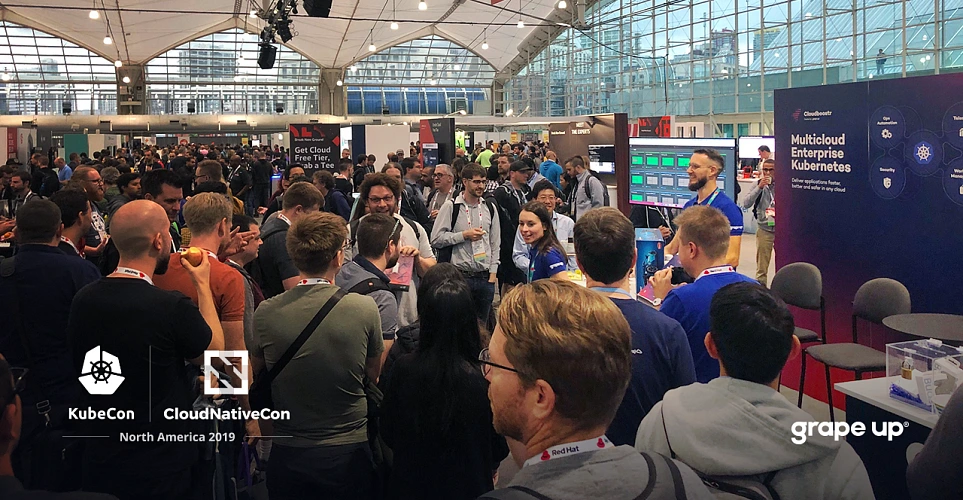
It’s obvious when tech companies present how they build their advantage using the latest technologies, but it becomes more intriguing when you have an opportunity to get to know how companies like Adidas, Nike or Tinder (yes, indeed) are using Kubernetes to provide their customers/users with extraordinary value.
As attached examples show, we live in the software-driven world, where the quality of delivered apps is crucial to stay relevant, regardless of the industry.
Enterprises need container orchestration to sustain their market share
The conference confirmed that Kubernetes is a standard in container orchestration and one of the key elements contributing to the successful implementation of a cloud-first strategy for enterprises.
But why the largest companies should be interested in adopting the newest technologies? Because their industries are being constantly disrupted by fresh startups utilizing agility and cutting-edge tech solutions. The only way to sustain position is by evolving. The way to achieve it comes to adopting a cloud-native strategy and implementing Kubernetes. As Jonathan Smart once said - “You’re never done with improving and learning.”
Automate what can be automated
As more and more teams move Kubernetes to production, a large number of companies is working on solutions that would help streamline and automate certain processes. That drives to the growing market of tools associated with Kubernetes and enriching its usage.
For example, Helm, which has its place in the native cloud toolbox used by administrators as one of the key deployment tools in its latest version, simplifies and improves operation by getting rid of some dependencies, such as Tiller, a server-side component running in the Kubernetes cluster.
Kubernetes-as-a-service and demand for Kubernetes experts
During this year’s KubeCon, many vendors presented a range of domains that have been offering complete solutions for Kubernetes, accelerating container orchestration. At previous events, we met vendors who have been providing storage, networking, and security components for Kubernetes. This evolution expresses the development of the environment built around the platform. Such an extensive offer of solutions allows teams or organizations to migrate to the native cloud to facilitate finding a compromise regarding "building versus buying" concerning components and solutions.
Rancher announced a solution that may be an example of an interesting Kubernetes-as-a-service option. The company collaborated with ARM to design a highly optimized version of Kubernetes for the edge - packaged as a single binary with a small footprint to reduce the dependencies and steps needed to install and run K8s in resource-constrained environments (e.g. IoT or edge devices for ITOps and DevOps teams.) By making K3s (lightweight distribution built for small footprint workloads) available and providing the beta release of Rio, their new application deployment engine for Kubernetes, Rancher delivers integrated deployment experience from operations to the pipeline.
Kubernetes-as-a-service offerings on the market are gaining strength. The huge number of Kubernetes use cases entails another very important trend. Companies are looking for talent in this field more than ever. Many companies have used conferences to meet with experts. Therefore, the number of Kubernetes jobs has also increased. The demand for experts on the subject is huge.
Multicloud is here to stay
Are hybrid solutions becoming a standard? Many cloud providers have claimed to be the best providers for multi-clouds - and we observe the trend that it becomes more popular. Despite some doubts (regarding its complexity, security, regulatory, or performance) enterprises are dealing well with implementing a multicloud strategy.
Top world’s companies are moving to multicloud as this approach empowers them to gain exceptional agility and huge cost savings thanks to the possibility to separate their workloads into different environments and make decisions based on the individual goals and specific requirements.
It is also a good strategy for companies working with private cloud-only. Usually, that’s the case because of storing sensitive data. As numerous case studies show, these businesses can be architected into multicloud solutions, whereas sensitive data is still stored securely on-premise, while other things are moved into the public cloud, which makes them easily scalable and easier to maintain.
Kubernetes is everywhere, even in the car….
During KubeCon, Rafał Kowalski, our colleague from Grape Up shared his presentation about running Kubernetes clusters in the car - "Kubernetes in Your 4x4 - Continuous Deployment Direct to the Car". Rafał showed how to use Kubernetes, KubeEdge, k3s, Jenkins, and RSocket for building continuous deployment pipelines, which ship software directly to the car, deals with rollbacks and connectivity issues. You can watch the entire video here:
https://www.youtube.com/watch?v=zmuOxFp3CAk&feature=youtu.be
…. and can be used in various devices
But these are not all of the possibilities; other devices such as drones or any IoT devices can also utilize containers The need for increased automation of cluster management and the ability to quickly rebuild clusters from scratch were the conclusions breaking through the above-mentioned occurrences.
The environment shows, through the remarkable pattern of the number of companies using Kubernetes and the development of utilities, there are still open needs in terms of simplicity and scalability of tools for operations, e.g. Security, data management, programming tools, and continuing operations in this area should be expected.
“Kubernetes has established itself as the de facto standard for container orchestration,”- these are the most frequently repeated words. It’s good to observe the development of the ecosystem around Kubernetes that strives to provide more reliable and cheaper experiences for enterprises that want to extend their strategic initiatives to the limit.
Benefits of using Immutable.js with React & Redux apps
Have you ever struggled with complex and unreadable redux reducers? If yes, this article will show you how Immutable.js can help you keep reducers easy and clean. It fits perfectly with the redux & react application, so you might try to use it in your app.
Immutable.js is a library that supports an immutable data structure. It means that once created data cannot be changed. It makes maintaining immutable data structures easier and more efficient. The tool supports data structure like: List, Map, Set and also structures that are not implemented in .js by default but can be very useful: OrderedMap, OrderedSet and Record.
Methods such as push, unshift, slice in .js are based on reference and mutate the object directly. In the case of Immutable.js, there are no methods that change the object directly, a new object is always returned.
How using Immutable.js is supposed to help in Redux applications?
Before using Immutable.js, the biggest issue with the Redux library often comes to returning a new object, which is nested in another object. In this case, using the Object.assign and spread operator syntax is not readable and may increase app complexity.
Some may suggest keeping your reducer's state as flat as possible. That could be right, but sometimes, even if your state is flat, you would have to set something in a nested object. So, if you also struggle because of that, the immutable library comes to make your life easier.
How does it look in practice?
Let’s start by showing some examples of how the code looks like with and without using our solution in a reducer. In most of the cases in reducers, you will use method .set , which takes two arguments; the first one is a key which you would like to change and the second one is a new value. For setting nested properties, you can use method .setIn , which instead of a key as the first argument takes a key path as an array. Worth noting here is that if the key does not exist, a new one will be created. Thanks to this, you don't have to make conditions to handle it.
Here is a very simple reducer:
export const initialState ={
loaded: false,
disabled: false
};
export default function bookReducer(state = initialState, { type, payload }) {
switch (type) {
case ActionTypes.setLoadedState:
return {
...state,
loaded: payload
}
}
return state;
}
This is the simplest reducer you can imagine, let's see what it looks like with immutable.js:
export const initialState = from.js({
loaded: false,
disabled: false
});
export default function bookReducer(state = initialState, { type, payload }) {
switch (type) {
case ActionTypes.setLoadedState:
return state.set('loaded', payload)
}
return state;
}
Here, there is no big difference because the reducer is very simple, but we already can see a small improvement, code becomes more readable.
The second example without our solution:
export const initialState = {
students: {},
selectedStudent: null
};
export default function studentReducer(state = initialState, { type, payload }) {
switch (type) {
case ActionTypes.setStudentStatus:
return {
...state,
students: {
...state.students,
[payload.studentId]: {
...state.students[payload.studentId],
status: payload.status
}
}
}
}
return state;
}
With Immutable.js:
export const initialState = {
students: {},
selectedStudent: null
};
export default function studentReducer(state = initialState, { type, payload }) {
switch (type) {
case ActionTypes.setStudentStatus:
return state.setIn(['students', payload.studentId, 'status'], payload.status)
}
return state;
}
In the example above, we can see a huge difference between using and not using the tool:
- The code is much shorter (10 lines to just 1 line).
- With the Immutable.js you can easily see at first glance what data in reducer has changed.
- Without the Immutable.js, it’s not that literal and obvious what’s changed.
In these examples, we provide only 2 methods of using Immutable.js - .set and .setIn , but there are numerous use cases, not only to set values. Actually, Immutable objects have the same methods which native .js has and a lot more which can speed up your development.
We also recommend checking the .update and .updateIn methods in the documentation, because, in reducers, they can be invaluable in more complex cases.
Other benefits of using Immutable.js
The main benefits of this library are easy and simple to maintain reducers. Besides this, we also get other advantages:
- The library provides data structures that are not natively implemented in .js, but it makes your life easier (e.g., Ordered Map, Record).
- The tool offers numerous ways to simplify your work, for example sortBy, groupBy, reverse, max, maxBy, flatten and many more. You can even stop using the lodash library, as most of the methods from lodash have their equivalents in immutable.js. It is easier to use as we can use chaining by default.
- Immutable.js does a lot of things under the hood, which improves performance. Immutable data structures usually consume a lot of RAM, because this approach requires creating new copies of objects constantly. Among other things, our solution optimizes this, by sharing the state cleverly.
- Empty collections are always equal, even if they were created separately. Look at the example below:

Compared to native .js:

There is always the other side of the coin, what are the cons?
Expensive converting to regular JavaScript
To convert Immutable collection to regular .js, you have to use .to.js() on an Immutable Collection. This method is very expensive when it comes to performance and always returns a new reference of an object even if nothing has been changed in the object. It affects PureComponent and React.memo, because these components would detect something has been changed, but actually, nothing has changed.
In most of the cases, you should avoid using to.js() and pass to components Immutable collections. However, sometimes you will have to use to.js, e.g. if you use an external library that requires props.
If you are developing generic components that will be used in other projects, you should avoid using an Immutable Collection in them, because it would force you to use Immutable in all projects that use these components.
There is no destructing operator
If you like getting properties using a destructing operator like this:
const { age, status } = student;
You won’t be happy, because, in Immutable.js, it is impossible to do. The get property from an immutable collection you have to use method .get or getIn, but I think it should not be a bit deal.
Debugging
Immutable collections are difficult to read in the browser console. Fortunately, you can easily solve this problem by using the tool. Object Formatter browser plugin, but it is not available in all browsers.
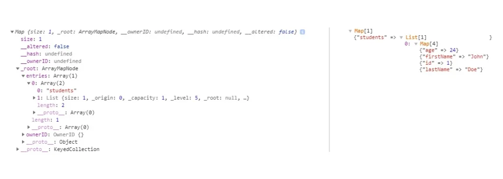
The above comparison shows what it looks like without and with the plugin. As you can see, the log is completely unreadable without the plugin.
Conclusion
Accordingly to our experiences, the immutable.js library is worth trying out in React applications with Redux applications. Thanks to immutable.js, your application will be more efficient, easier to develop, maintain and more resistant to errors . Because, as you’ve seen above in a comparison of reducers. It's definitely easier to make a mistake without using Immutable.js. In the long term project, you should definitely consider it.
Deliver your apps to Kubernetes faster
Kubernetes is currently the most popular container orchestration platform used by enterprises, organizations and individuals to run their workloads . Kubernetes provides software developers with great flexibility in how they can design and architect systems and applications.
Unfortunately, its powerful capabilities come at a price of the platform’s complexity, especially from the developer’s perspective. Kubernetes forces developers to learn and understand its internals fluently in order to deploy workloads, secure them and integrate with other systems.
Why is it so complex?
Kubernetes uses the concept of Objects, which are abstractions representing the state of the cluster. When one wants to perform some operation on the cluster e.g., deploy an application, they basically need to make the cluster create several various Kubernetes Objects with an appropriate configuration. Typically, when you would like to deploy a web application, in the simplest case scenario, you would need to:
- Create a deployment.
- Expose the deployment as a service.
- Configure ingress for the service.
However, before you can create a deployment (i.e. command Kubernetes to run a specific number of containers with your application), you need to start with building a container image that includes all the necessary software components to run your app and of course the app itself. “Well, that’s easy” – you say – “I just need to write a Dockerfile and then build the image using docker build ”. That is all correct, but we are not there yet. Once you have built the image, you need to store it in a container image registry where Kubernetes can pull it from.
You could ask - why is it so complex? As a developer, I just want to write my application code and run it, rather than additionally struggle with Docker images, registries, deployments, services, ingresses, etc., etc. But that is the price for Kubernetes’ flexibility. And that is also what makes Kubernetes so powerful.
Making deployments to Kubernetes easy
What if all the above steps were automated and combined into a single command allowing developers to deploy their app quickly to the cluster? With Cloudboostr’s latest release, that is possible!
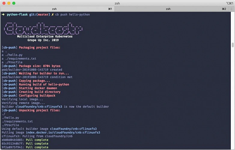
What’s new? The Cloudboostr CLI - a new command line tool designed to simplify developer experience when using Kubernetes. To deploy an application to the cluster, you simply execute a single command:
cb push APP_NAME
The concept of “pushing” an application to the cluster has been borrowed from the Cloud Foundry community and its famous cf push command described by cf push haiku:
Here is my source code
Run it on the cloud for me
I do not care how.
When it comes to Cloudboostr , the “push” command automates the app deployment process by:
- Building the container image from application sources.
- Pushing the image to the container registry.
- Deploying the image to Kubernetes cluster.
- Configuring service and ingress for the app.
Looking under the hood
Cloudboostr CLI uses the Cloud Native Buildpacks project to automatically detect the application type and build an OCI-compatible container image with an appropriate embedded application runtime. Cloud Native Buildpacks can autodetect the most popular application languages and frameworks such as Java, .NET, Python, Golang or NodeJS.
Once the image is ready, it is automatically pushed to the Harbor container registry built into Cloudboostr. By default, Harbor is accessible and serves as a default registry for all Kubernetes clusters deployed within a given Cloudboostr installation. The image stored in the registry is then used to create a deployment in Kubernetes. In the current release only standard Deployment objects are supported, but adding support for StatefulSets is in the roadmap. As the last step, a service object for the application is created and a corresponding ingress object configured with Cloudboostr’s built-in Traefik proxy.
The whole process described above is executed in the cluster. Cloudboostr CLI triggers the creation of a temporary builder container that is responsible for pulling the appropriate buildpack, building the container image and communicating with the registry. The builder container is deleted from the cluster after the build process finishes. Building the image in the cluster eliminates the need to have Docker and pack (Cloud Native Buildpacks command line tool) installed on the local machine.
Cloudboostr CLI uses configuration defined in kubeconfig to access Kubernetes clusters. By default, images are pushed to the Harbor registry in Cloudboostr, but the CLI can also be configured to push images to an external container registry.
Why bother a.k.a. the benefits
While understanding Kubernetes internals is extremely useful, especially for troubleshooting and debugging, it should not be required when you just want to run an app. Many development teams that start working with Kubernetes find it difficult as they would prefer to operate on the application level rather than interact with containers, pods, ingresses, etc. The “cb push” command aims to help those teams and give them a tool to deliver fast and deploy to Kubernetes efficiently.
Cloudboostr was designed to tackle common challenges that software development teams face using Kubernetes. It became clear that we could improve the entire developer experience by providing those teams with a convenient yet effective tool to migrate from Cloud Foundry to Kubernetes. A significant part of that transition came to offer a feature that makes deploying apps to Kubernetes as user-friendly as Cloud Foundry does. That allows developers to work intuitively and with ease.
Cloudboostr CLI significantly simplifies the process of deploying applications to a Kubernetes cluster and takes the burden of handling containers and all Kubernetes-native concepts off of developers’ backs. It boosts the overall software delivery performance and helps teams to release their products to the market faster.

Serverless - why, when and how?
This is the first article of the mini-series that will get you started with a Serverless architecture and the Function-as-a-Service execution model - whose popularity is constantly growing. In this part, you will get answers to some of the most popular questions regarding Serverless, including: what is it, why it’s worth your attention, how does it work under the hood and which cloud provider meets your needs.
No servers at all?
Not really, your code has to be executed somewhere. Okay, so what is it all about then?
Serverless is a cloud computing execution model in which computer resources are dynamically allocated and managed by a cloud provider of your choice. Among serverless databases, storages, analytic tools, and many others, there is also Function-as-a-Service that we will focus on in this article.
FaaS is a serverless backend service that lets you execute and manage your code without bothering about the infrastructure that used to run your apps on it. In simple terms, you can order a function call without caring about how and where it is performed.
Why?
For money, as Serverless is extremely cost-effective in cases described in the next paragraph. In the serverless cloud execution model, you pay only for used resources, you don’t pay a penny when your code is not being executed!
Moreover, neither actual hardware nor public cloud infrastructure costs a company as much as software engineers’ time. Employees are the most cost-consuming resources. Serverless lets developers focus on functionalities instead of server provisioning, hardening and maintaining infrastructure.
Serverless services scale automatically when needed. You can control their performance by toggling memory and throughput. Furthermore, you don’t have to worry about thunderstorms or any other issues! Serverless services come with built-in high availability and fault tolerance features, meaning your function will be executed even if the primary server has blown up.
When to consider serverless?
Whenever you are preparing a proof of concept or prototyping application… Serverless functions do not generate costs at low workloads and are always ready to deal with the situations they increase. Combining this feature with no server management, it significantly accelerates the delivery of MVP.
When it comes to production, a Serverless architecture fits stateless applications like REST / GraphQL APIs very well. It is much easier, faster and cheaper to get such applications up and running. Services with unpredictable load pikes and inactivity periods, as well as cron jobs (running periodically) are also a great use case examples of FaaS.
Imagine the management of an application for ordering lunch. It has very high load peaks around noon, and it is unused for the rest of the day. Why pay for servers hosting such an application 24 hours a day, instead of paying just for the time when it is really used?
A Serverless architecture is often used for data processing, video streaming and handling IoT events. It is also very handy when it comes to integrating multiple SaaS services. Implementing a facade on top of a running application, for the purpose of migrating it or optimization can also be done much easier using this approach. FaaS is like cable ties and insulating tape in a DIY toolbox.
Where’s the catch?
It would be too good if there weren’t any catches. Technically, you could get a facebook-like application up and running using Serverless services, but it would cost a fortune! It turns out that such a solution would cost thousands of times more than hosting it on regular virtual machines or your own infrastructure. Serverless is also a bad choice for applications using sockets to establish a persistent connection with a server described in Rafal’s article about RSocket . Such a connection would need to be reestablished periodically as Lambda stays warmed-up for about 10 minutes after the last call. In this approach, you would be billed for the time of established connection.
Moreover, your whole solution becomes vendor bound. There are situations when a vendor raises prices, or another cloud provider offers new cool features. It is harder to switch between them, once you have your application up and running. The process takes time, money and the other vendor may not offer all the services that you need.
Furthermore, It is harder to troubleshoot your function, and almost every vendor enforces you to use some additional services to monitor logs from the execution - that generate extra costs. There is also a bit less comfortable FaaS feature that we have to take into account - “Cold start”. From time to time, it makes your function work much longer than usual. Depending on the vendor, there are different constraints on function execution time, which might be exceeded because of it. The following paragraph will explain this FaaS behavior in detail.
How does it work?
It is a kind of a mystery what can we find under the hood of FaaS. There are many services and workers that are responsible for orchestrating function invocations, concurrency management, tracking containers busy and idle states, scheduling incoming invocations appropriately, etc. The technology stack differs between vendors, but the general scheme is the same and you can find it below.
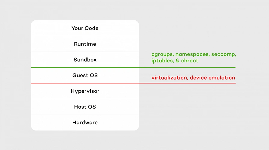
Hypervisor which emulates real devices is the first layer of isolation. The second one consists of containers and OS separation that comes with it. Our code is executed on a sandbox container with an appropriate runtime installed on it. A sandbox is being set up (so-called “Cold start” mentioned above) whenever a function is called for the first time after making changes or hasn’t been invoked for 5 - 15 minutes (depending on the vendor). It means that containers persist between calls, which accelerates execution but is also a bit tricky sometimes. For example, if we choose one of the interpreted languages as a runtime, all invocations are being performed on the same interpreter instance as long as the container lives. That means global variables and context are cached in memory between function executions, so keeping there sensitive data like tokens or passwords is a bad idea.
Containers’ load is balanced similarly to CPU resource allocation, which means they are not loaded equally. The workload is concentrated as much as possible, so runtime consumes the maximum capacity of a container. Thanks to that, other containers in the pool are unused and ready to run another function in the meantime.
Which vendor to pick?
Serverless services are offered by many cloud providers like AWS, GCP, Microsoft Azure, and IBM among others. It’s hard to say which one to choose, as it depends on your needs. The main differences between them are: pricing, maximum execution time, supported runtimes and concurrency. Let’s take a brief look at the comparison below.
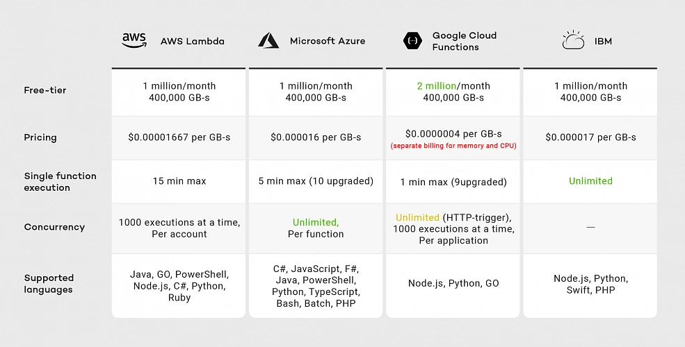
As of the second half of 2019, you can see that all vendors provide similar pricing except Google. Although Google’s free-tier offer seems promising because of the doubled number of free requests, when we exceed this limit, we have two separate billings for memory and CPU, meaning Google’s pricing model is the most expensive.
Considering execution time IBM and AWS Lambda are the best choices. Although IBM has no time limit for single-function execution, it’s concurrency rate remains unclear. IBM documentation does not guarantee that functions will run concurrently. Google provides 1000 executions at a time per project, while AWS provides the same limit per account. That means you can run multiple Google Cloud Functions with the same concurrency, while on AWS you have to divide this limitation between all your functions.
If you look for a wide variety of supported runtimes, AWS and Azure are the best choices. While AWS supported languages list has not changed much since 2014, Google was providing only JavaScript runtime until June 2019. That means AWS runtimes may be more reliable than Google’s.
In the next article in the series, I will focus on AWS, which has a wide range of services that can be integrated with AWS Lambda for the purpose of building more complete applications. Moreover, AWS has a large community around it, which helps when a problem arises.
Summary
In this article, I tried to address the most common questions regarding Serverless architecture and the Function-as-a-Service execution model. I suggested when to use it, and when not to. We took a brief tour of what lays under the hood of FaaS and compared its vendors.
In the next articles, we will explore AWS. I will guide you through Amazon serverless services and help you create your first serverless application using them.
Testing iOS applications using Appium, Cucumber, and Serenity - a recipe for quality
iOS devices still claim a significant part of the mobile market, taking up to 22 percent of the sales globally. As many devoted clients come back for new Apple products, there is also a great demand for iOS applications. In this article, we are going to look at ensuring the quality of iOS apps striving for the usage of best practices using Appium, Cucumber and Serenity tools.
Structure
The Page Object Model is one of the best approaches to testing that QA engineers can apply to a test automation project. It is such a way of structuring the code in an automation project that improves code quality and readability, test maintenance and on top of that, it is a great way of avoiding chaos. The basic idea behind it comes to keeping all references to mobile elements and methods performing operations on them in one class file for each page or screen of the app (or web page for non-native web applications).
What are the benefits of this approach, you may ask? Firstly, it makes automation really straightforward. Basically, it means finding elements in our iOS app via inspector and then performing operations on them. Another main advantage is the coherent structure of the project that allows anyone to navigate through it quickly.
Let's take an example of an app that contains recipes. It shows the default cookbook with basic recipes on startup, which will be our first page. From there, a user can navigate to any available recipe, thus marking a second page. On top of that, the app also allows to browse other cookbooks or purchase premium ones, making it the third page and consequently - a page object file.
Similarly, we should create corresponding step definition files. This is not an obligatory practice, but keeping all step definitions in one place causes unnecessary chaos.
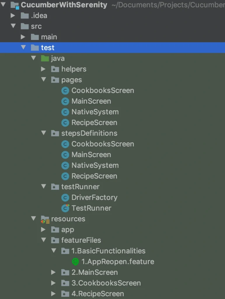
While creating your pages and step definition class files it is advised to choose names that are related to the page (app screen) which contents you are going to work on. Naming these files after a feature or scenario can seem right at first glance, but as the project expands, you will notice more and more clutter in its structure. Adopting the page naming convention ensures that anyone involved in the project can get familiar with it straight away and start collaboration on it in no time. Such practice also contributes to reusability of code - either step definitions or methods/functions.
Contrary to the mentioned step and step definition files, the Cucumber feature files should be named after a feature they verify. Clever, isn’t it? And again, structuring them into directories named in relation to a particular field of the application under test will make the structure more meaningful.
Serenity’s basic concept is to be a 'living documentation'. Therefore, giving test scenarios and feature files appropriate names helps the team and stakeholders understand reports and the entire project better.
Another ingredient expanding the benefits of the Page Object Model in the test automation project is PageFactory. It is a tool that helps you reduce the coding work and easily put MobileElements locators in code, using @FindBy notation. From there, finding elements for Appium to interact with them in tests is much simpler.
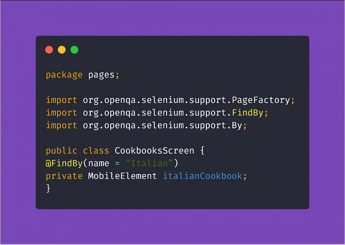
Assertion
Running tests via Appium can be very resource-consuming. To make things easier for your MacOS machine running tests on your iOS device, make sure you are not constantly asserting the visibility of all objects on a page. This practice significantly increases the test execution time, which usually is not the most desirable thing.
What is more, when you do have to check if an element is visible, enabled, clickable, or anything in between - try to avoid locating mobile elements using Xpath. The Appium inspector tip has a valid point! You should do what you can to convince the development team to make an extra effort and assign unique IDs and names to the elements in the app. This will not only make automation testing easier and quicker, consequently making your work as a tester more effective, ultimately resulting in increasing the overall quality of the product. And that is why we are here. Not to mention that the maintenance of the tests (e.g. switching to different locators when necessary) will become much more enjoyable.
Understanding the steps
Another aspect of setting up this kind of project comes down to taking advantage of Cucumber and using Gherkin language.
Gherkin implements a straightforward approach with Given, When, Then notation with the help of the additional And and But which seems fairly easy to use. You could write pretty much anything you want in the test steps of your feature files. Ultimately, the called methods are going to perform actions.
But the reason for using the Behavior Driven Development approach and Cucumber itself is enabling the non-tech people involved in the project to understand what is going on in the tests field. Not only that, writing test scenarios in Given/When/Then manner can also act in your advantage. Such high-level test descriptions delivered by the client or business analyst will get you coding in no time, provided that they are written properly. Here are some helpful tips:
Test scenarios written in Gherkin should focus on the behavior of the app (hence Behavior Driven Development).
Here's an example of how NOT to write test scenarios in Gherkin, further exploring the theme of cookbook application:
Above example illustrates two bad practices we should avoid: It focuses on the implementation instead of behavior and it uses hard-coded values rather than writing test steps in such a way to enable reusability by changing values within a step.
Therefore, a proper scenario concerning purchasing a cookbook in our example app should look like:
Another example:
Adopting this approach means less work creating and coding the test steps whenever the implementation of a particular feature changes.
Apart from the main notation of Given/When/Then , Cucumber supports usage of conjunction steps. Using And and But step notations will make the test steps more general and reusable, which results in writing less code and maintaining order within the project. Here is a basic example:
Doing so, if you code the above 'Given' step to locate our recipe element by searching its name, you can reuse it many times just changing the string value in the step (provided that you code the step definition properly later on). On top of that, The 'And' step can be a part of any test scenario that involves such action.
Putting it all together
After setting up a project utilizing the practices described above, the most visible parts of using Serenity are the generated test reports. After adopting the @RunWith(CucumberWithSerenity.class) tag in your TestRunner class file, running the test suite will result in Serenity generating an aggregated test results report, which can be useful in evaluating the quality of the app under test and presenting the status of the product to the stakeholders or the development team.
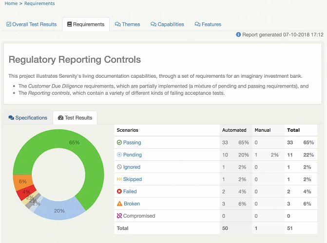
Appium, Cucumber, Serenity - summary
As you can see, the concept of best practices in automation testing can be summarized in three words: reusability, readability, and performance. Reusability means fewer coding, consequently diminishing the time needed to finish the job. Readability improves understanding, which is crucial to ensure that the product does what it needs to do. Finally, performance saves execution time and improves stability. All three contributing not only to the quality of the test automation project but have a significant role in enhancing the overall quality of the delivered app.
Sources:

How to successfully adopt Kubernetes in an enterprise?
Kubernetes has practically become the standard for container orchestration. Enterprises see it as one of the crucial elements contributing to the success of the implementation of a cloud-first strategy. Of course, Kubernetes is not the most important success factor in going cloud-native. But the right tooling is the enabler for achieving DevOps maturity in an enterprise, which builds primarily on cultural change and shift in design thinking. This article highlights the most common challenges an enterprise encounters while adopting Kubernetes and recommendations on how to make Kubernetes adoption smooth and effective in order to drive productivity and business value.
Challenges in Kubernetes adoption
Kubernetes is still complex to set up. Correct infrastructure and network setup, installation, and configuration of all Kubernetes components are not that straightforward even though there are tools created with the goal to streamline that part.
Kubernetes alone is not enough. Kubernetes is not a cloud-native platform by itself, but rather one of the tools needed to build a platform. A lot of additional tooling is needed to create a manageable platform that improves developers’ experience and drives productivity. Therefore, it requires a lot of knowledge and expertise to choose the right pieces of the puzzle and connect them in the right way.
Day 2 operations are not easy. When the initial problems with setup and installation are solved, there comes another challenge: how to productionize the platform, onboard users, and manage Kubernetes clusters at scale. Monitoring, upgrading & patching, securing, maintaining high availability, handling backups – these are just a few operational aspects to consider. And again, it requires a lot of knowledge to operate and manage Kubernetes in production.
Another aspect is the platform’s complexity from the developer’s perspective. Kubernetes requires developers to understand its internals in order to use it effectively for deploying applications, securing them and integrating them with external services.
Recommendations for a successful Kubernetes adoption
Choose a turnkey solution – do not build the platform by yourself as the very first step, considering the aforementioned complexity. It is better to pick a production-ready distribution, that allows to set it up quickly and focus on managing the cultural and organizational shift rather than struggling with the technology. Such a solution should offer a right balance between how much is pre-configured and available out-of-the-box, and the flexibility to customize it further down the road. Of course, it is good when the distribution is compatible with the upstream Kubernetes as it allows your engineers and operators to interact with native tools and APIs.
Start small and grow bigger in time – do not roll out Kubernetes for the whole organization immediately. New processes and tools should be introduced in a small, single team and incrementally spread throughout the organization. Adopting Kubernetes is just one of the steps on the path to cloud-native and you need to be cautious not to slip. Start with a single team or product, learn, gain knowledge and then share it with other teams. These groups being the early adopters, should eventually become facilitators and evangelists of Kubernetes and DevOps approach, and help spread these practices throughout the organization. This is the best way to experience Kubernetes value and understand the operational integration required to deliver software to production in a continuous manner.
Leverage others’ experiences – usually, it is good to start with the default, pre-defined or templated settings and leverage proven patterns and best practices in the beginning. As you get more mature and knowledgeable about the technology, you can adjust, modify and reconfigure iteratively to make it better suit your needs. At this point, it is good to have a solution which can be customized and gives the operator full control over the configuration of the cluster. Managed and hosted solutions, even though easy to use at the early stage of Kubernetes adoption, usually leave small to no space for custom modifications and cluster finetuning.
When in need, call for backups – it is good to have cavalry in reserve which can come to the rescue when bad things happen or simply when something is not clear. Secure yourself for the hard times and find a partner who can help you learn and understand the complexities of Kubernetes and other building blocks of the cloud-native toolset. Even when your long-term strategy is to build the Kubernetes skills in-house (both from development and operations perspective).
Do not forget about mindset change – adopting the technology is not enough. Starting to deploy applications to Kubernetes will not instantly transform your organization and speed up software delivery. Kubernetes can become the cornerstone in the new DevOps way the company builds and delivers software but needs to be supported by organizational changes touching many more areas of the company than just tools and technology: the way people think, act and work, the way they communicate and collaborate. And it is essential to educate all stakeholders at all levels throughout the adoption process, to have a common understanding of what DevOps is, what changes it brings and what are the benefits.
Adopting Kubernetes in an Enterprise - conclusion
Even though Kubernetes is not easy, it is definitely worth the attention. It offers a great value in the platform you can build with it and can help transition your organization to the new level. With Kubernetes as the core technology and DevOps approach to software delivery , the company can accelerate application development, manage its workflows more efficiently and get to the market faster.
Reactive service to service communication with RSocket – abstraction over RSocket
If you are familiar with the previous articles of this series ( Introduction , Load balancing & Resumability ), you have probably noticed that RSocket provides a low-level API. We can operate directly on the methods from the interaction model and without any constraints sends the frames back and forth. It gives us a lot of freedom and control, but it may introduce extra issues, especially related to the contract between microservices. To solve these problems, we can use RSocket through a generic abstraction layer. There are two available solutions out there: RSocket RPC module and integration with Spring Framework. In the following sections, we will discuss them briefly.
RPC over RSocket
Keeping the contract between microservices clean and well-defined is one of the crucial concerns of the distributed systems. To assure that applications can exchange the data we can leverage Remote Procedure Calls. Fortunately, RSocket has dedicated RPC module which uses Protobuf as a serialization mechanism, so that we can benefit from RSocket performance and keep the contract in check at the same time. By combining generated services and objects with RSocket acceptors we can spin up fully operational RPC server, and just as easily consume it using RPC client.
In the first place, we need the definition of the service and the object. In the example below, we create simple CustomerService with four endpoints – each of them represents a different method from the interaction model.
syntax = "proto3";
option java_multiple_files = true;
option java_outer_classname = "ServiceProto";
package com.rsocket.rpc;
import "google/protobuf/empty.proto";
message SingleCustomerRequest {
string id = 1;
}
message MultipleCustomersRequest {
repeated string ids = 1;
}
message CustomerResponse {
string id = 1;
string name = 2;
}
service CustomerService {
rpc getCustomer(SingleCustomerRequest) returns (CustomerResponse) {} //request-response
rpc getCustomers(MultipleCustomersRequest) returns (stream CustomerResponse) {} //request-stream
rpc deleteCustomer(SingleCustomerRequest) returns (google.protobuf.Empty) {} //fire'n'forget
rpc customerChannel(stream MultipleCustomersRequest) returns (stream CustomerResponse) {} //request-channel
}
In the second step, we have to generate classes out of the proto file presented above. To do that we can create a gradle task as follows:
protobuf {
protoc {
artifact = 'com.google.protobuf:protoc:3.6.1'
}
generatedFilesBaseDir = "${projectDir}/build/generated-sources/"
plugins {
rsocketRpc {
artifact = 'io.rsocket.rpc:rsocket-rpc-protobuf:0.2.17'
}
}
generateProtoTasks {
all()*.plugins {
rsocketRpc {}
}
}
}
As a result of generateProto task, we should obtain service interface, service client and service server classes, in this case, CustomerService , CustomerServiceClient , CustomerServiceServer respectively. In the next step, we have to implement the business logic of generated service (CustomerService):
public class DefaultCustomerService implements CustomerService {
private static final List RANDOM_NAMES = Arrays.asList("Andrew", "Joe", "Matt", "Rachel", "Robin", "Jack");
@Override
public Mono getCustomer(SingleCustomerRequest message, ByteBuf metadata) {
log.info("Received 'getCustomer' request [{}]", message);
return Mono.just(CustomerResponse.newBuilder()
.setId(message.getId())
.setName(getRandomName())
.build());
}
@Override
public Flux getCustomers(MultipleCustomersRequest message, ByteBuf metadata) {
return Flux.interval(Duration.ofMillis(1000))
.map(time -> CustomerResponse.newBuilder()
.setId(UUID.randomUUID().toString())
.setName(getRandomName())
.build());
}
@Override
public Mono deleteCustomer(SingleCustomerRequest message, ByteBuf metadata) {
log.info("Received 'deleteCustomer' request [{}]", message);
return Mono.just(Empty.newBuilder().build());
}
@Override
public Flux customerChannel(Publisher messages, ByteBuf metadata) {
return Flux.from(messages)
.doOnNext(message -> log.info("Received 'customerChannel' request [{}]", message))
.map(message -> CustomerResponse.newBuilder()
.setId(UUID.randomUUID().toString())
.setName(getRandomName())
.build());
}
private String getRandomName() {
return RANDOM_NAMES.get(new Random().nextInt(RANDOM_NAMES.size() - 1));
}
}
Finally, we can expose the service via RSocket. To achieve that, we have to create an instance of a service server (CustomerServiceServer) and inject an implementation of our service (DefaultCustomerService). Then, we are ready to create an RSocket acceptor instance. The API provides RequestHandlingRSocket which wraps service server instance and does the translation of endpoints defined in the contract to methods available in the RSocket interaction model.
public class Server {
public static void main(String[] args) throws InterruptedException {
CustomerServiceServer serviceServer = new CustomerServiceServer(new DefaultCustomerService(), Optional.empty(), Optional.empty());
RSocketFactory
.receive()
.acceptor((setup, sendingSocket) -> Mono.just(
new RequestHandlingRSocket(serviceServer)
))
.transport(TcpServerTransport.create(7000))
.start()
.block();
Thread.currentThread().join();
}
}
On the client-side, the implementation is pretty straightforward. All we need to do is create the RSocket instance and inject it to the service client via the constructor, then we are ready to go.
@Slf4j
public class Client {
public static void main(String[] args) {
RSocket rSocket = RSocketFactory
.connect()
.transport(TcpClientTransport.create(7000))
.start()
.block();
CustomerServiceClient customerServiceClient = new CustomerServiceClient(rSocket);
customerServiceClient.deleteCustomer(SingleCustomerRequest.newBuilder()
.setId(UUID.randomUUID().toString()).build())
.block();
customerServiceClient.getCustomer(SingleCustomerRequest.newBuilder()
.setId(UUID.randomUUID().toString()).build())
.doOnNext(response -> log.info("Received response for 'getCustomer': [{}]", response))
.block();
customerServiceClient.getCustomers(MultipleCustomersRequest.newBuilder()
.addIds(UUID.randomUUID().toString()).build())
.doOnNext(response -> log.info("Received response for 'getCustomers': [{}]", response))
.subscribe();
customerServiceClient.customerChannel(s -> s.onNext(MultipleCustomersRequest.newBuilder()
.addIds(UUID.randomUUID().toString())
.build()))
.doOnNext(customerResponse -> log.info("Received response for 'customerChannel' [{}]", customerResponse))
.blockLast();
}
}
Combining RSocket with RPC approach helps to maintain the contract between microservices and improves day to day developer experience. It is suitable for typical scenarios, where we do not need full control over the frames, but on the other hand, it does not limit the protocol flexibility. We can still expose RPC endpoints as well as plain RSocket acceptors in the same application so that we can easily choose the best communication pattern for the given use case.
In the context of RPC over the RSocket one more fundamental question may arise: is it better than gRPC? There is no easy answer to that question. RSocket is a new technology, and it needs some time to get the same maturity level as gRPC has. On the other hand, it surpasses gRPC in two areas: performance ( benchmarks available here ) and flexibility - it can be used as a transport layer for RPC or as a plain messaging solution. Before making a decision on which one to use in a production environment, you should determine if RSocket align with your early adoption strategy and does not put your software at risk. Personally, I would recommend introducing RSocket in less critical areas, and then extend its usage to the rest of the system.
Spring boot integration
The second available solution, which provides an abstraction over the RSocket is the integration with Spring Boot. Here we use RSocket as a reactive messaging solution and leverage spring annotations to link methods with the routes with ease. In the following example, we implement two Spring Boot applications – the requester and the responder. The responder exposes RSocket endpoints through CustomerController and has a mapping to three routes: customer , customer-stream and customer-channel . Each of these mappings reflects different method from RSocket interaction model (request-response, request stream, and channel respectively). Customer controller implements simple business logic and returns CustomerResponse object with a random name as shown in the example below:
@Slf4j
@SpringBootApplication
public class RSocketResponderApplication {
public static void main(String[] args) {
SpringApplication.run(RSocketResponderApplication.class);
}
@Controller
public class CustomerController {
private final List RANDOM_NAMES = Arrays.asList("Andrew", "Joe", "Matt", "Rachel", "Robin", "Jack");
@MessageMapping("customer")
CustomerResponse getCustomer(CustomerRequest customerRequest) {
return new CustomerResponse(customerRequest.getId(), getRandomName());
}
@MessageMapping("customer-stream")
Flux getCustomers(MultipleCustomersRequest multipleCustomersRequest) {
return Flux.range(0, multipleCustomersRequest.getIds().size())
.delayElements(Duration.ofMillis(500))
.map(i -> new CustomerResponse(multipleCustomersRequest.getIds().get(i), getRandomName()));
}
@MessageMapping("customer-channel")
Flux getCustomersChannel(Flux requests) {
return Flux.from(requests)
.doOnNext(message -> log.info("Received 'customerChannel' request [{}]", message))
.map(message -> new CustomerResponse(message.getId(), getRandomName()));
}
private String getRandomName() {
return RANDOM_NAMES.get(new Random().nextInt(RANDOM_NAMES.size() - 1));
}
}
}
Please notice that the examples presented below are based on the Spring Boot RSocket starter 2.2.0.M4, which means that it is not an official release yet, and the API may be changed.
It is worth noting that Spring Boot automatically detects the RSocket library on the classpath and spins up the server. All we need to do is specify the port:
spring:
rsocket:
server:
port: 7000
These few lines of code and configuration set up the fully operational responder with message mapping (the code is available here )
Let’s take a look on the requester side. Here we implement CustomerServiceAdapter which is responsible for communication with the responder. It uses RSocketRequester bean that wraps the RSocket instance, mime-type and encoding/decoding details encapsulated inside RSocketStrategies object. The RSocketRequester routes the messages and deals with serialization/deserialization of the data in a reactive manner. All we need to do is provide the route, the data and the way how we would like to consume the messages from the responder – as a single object (Mono) or as a stream (Flux).
@Slf4j
@SpringBootApplication
public class RSocketRequesterApplication {
public static void main(String[] args) {
SpringApplication.run(RSocketRequesterApplication.class);
}
@Bean
RSocket rSocket() {
return RSocketFactory
.connect()
.frameDecoder(PayloadDecoder.ZERO_COPY)
.dataMimeType(MimeTypeUtils.APPLICATION_JSON_VALUE)
.transport(TcpClientTransport.create(7000))
.start()
.block();
}
@Bean
RSocketRequester rSocketRequester(RSocket rSocket, RSocketStrategies rSocketStrategies) {
return RSocketRequester.wrap(rSocket, MimeTypeUtils.APPLICATION_JSON,
rSocketStrategies);
}
@Component
class CustomerServiceAdapter {
private final RSocketRequester rSocketRequester;
CustomerServiceAdapter(RSocketRequester rSocketRequester) {
this.rSocketRequester = rSocketRequester;
}
Mono getCustomer(String id) {
return rSocketRequester
.route("customer")
.data(new CustomerRequest(id))
.retrieveMono(CustomerResponse.class)
.doOnNext(customerResponse -> log.info("Received customer as mono [{}]", customerResponse));
}
Flux getCustomers(List ids) {
return rSocketRequester
.route("customer-stream")
.data(new MultipleCustomersRequest(ids))
.retrieveFlux(CustomerResponse.class)
.doOnNext(customerResponse -> log.info("Received customer as flux [{}]", customerResponse));
}
Flux getCustomerChannel(Flux customerRequestFlux) {
return rSocketRequester
.route("customer-channel")
.data(customerRequestFlux, CustomerRequest.class)
.retrieveFlux(CustomerResponse.class)
.doOnNext(customerResponse -> log.info("Received customer as flux [{}]", customerResponse));
}
}
}
Besides the communication with the responder, the requester exposes the RESTful API with three mappings: /customers/{id} , /customers , /customers-channel . Here we use spring web-flux and on top of the HTTP2 protocol. Please notice that the last two mappings produce the text event stream, which means that the value will be streamed to the web browser when it becomes available.
@RestController
class CustomerController {
private final CustomerServiceAdapter customerServiceAdapter;
CustomerController(CustomerServiceAdapter customerServiceAdapter) {
this.customerServiceAdapter = customerServiceAdapter;
}
@GetMapping("/customers/{id}")
Mono getCustomer(@PathVariable String id) {
return customerServiceAdapter.getCustomer(id);
}
@GetMapping(value = "/customers", produces = MediaType.TEXT_EVENT_STREAM_VALUE)
Publisher getCustomers() {
return customerServiceAdapter.getCustomers(getRandomIds(10));
}
@GetMapping(value = "/customers-channel", produces = MediaType.TEXT_EVENT_STREAM_VALUE)
Publisher getCustomersChannel() {
return customerServiceAdapter.getCustomerChannel(Flux.interval(Duration.ofMillis(1000))
.map(id -> new CustomerRequest(UUID.randomUUID().toString())));
}
private List getRandomIds(int amount) {
return IntStream.range(0, amount)
.mapToObj(n -> UUID.randomUUID().toString())
.collect(toList());
}
}
To play with REST endpoints mentioned above, you can use following curl commands:
curl http://localhost:8080/customers/1
curl http://localhost:8080/customers
curl http://localhost:8080/customers-channel
Please notice that requester application code is available here
The integration with Spring Boot and RPC module are complementary solutions on top of the RSocket. The first one is messaging oriented and provides convenient message routing API whereas the RPC module enables the developer to easily control the exposed endpoints and maintain the contract between microservices. Both of these solutions have applications and can be easily combined with RSocket low-level API to fulfill the most sophisticated requirements with consistent manner using a single protocol.
Series summary
This article is the last one of the mini-series related to RSocket – the new binary protocol which may revolutionize service to service communication in the cloud. Its rich interaction model , performance and extra features like client load balancing and resumability make it a perfect candidate for almost all possible business cases. The usage of the protocol may be simplified by available abstraction layers: Spring Boot integration and RPC module which address most typical day to day scenarios.
Please notice that the protocol is in release candidate version (1.0.0-RC2), therefore it is not recommended to use it in the production environment. Still, you should keep an eye on it, as the growing community and support of the big tech companies (e.g. Netflix, Facebook, Alibaba, Netifi) may turn RSocket as a primary communication protocol in the cloud.
ASP.NET core CI/CD on Azure Pipelines with Kubernetes and Helm
Due to the high entry threshold, it is not that easy to start a journey with Cloud Native. Developing apps focused on reliability and performance, and meeting high SLAs can be challenging. Fortunately, there are tools like Istio which simplify our lives. In this article, we guide you through the steps needed to create CI/CD with Azure Pipelines for deploying microservices using Helm Charts to Kubernetes. This example is a good starting point for preparing your development process. After this tutorial, you should have some basic ideas about how Cloud Native apps should be developed and deployed .
Technology stack
- .NET Core 3.0 (preview)
- Kubernetes
- Helm
- Istio
- Docker
- Azure DevOps
Prerequisites
You need a Kubernetes cluster, free Azure DevOps account, and a docker registry. Also, it would be useful to have kubectl and gcloud CLI installed on your machine. Regarding the Kubernetes cluster, we will be using Google Kubernetes Engine from Google Cloud Platform, but you can use a different cloud provider based on your preferences. On GCP you can create a free account and create a Kubernetes cluster with Istio enabled ( Enable Istio checkbox). We suggest using a machine with 3 standard nodes.
Connecting the cluster with Azure Pipelines
Once we have the cluster ready, we have to use kubectl to prepare service account which is needed for Azure Pipelines to authenticate. First, authenticate yourself by including necessary settings in kubeconfig. All cloud providers will guide you through this step. Then following commands should be run:
kubectl create serviceaccount azure-pipelines-deploy
kubectl create clusterrolebinding azure-pipelines-deploy --clusterrole=cluster-admin --serviceaccount=default:azure-pipelines-deploy
kubectl get secret $(kubectl get secrets -o custom-columns=":metadata.name" | grep azure-pipelines-deploy-token) -o yaml
We are creating a service account, to which a cluster role is assigned. The cluster-admin role will allow us to use Helm without restrictions. If you are interested, you can read more about RBAC on Kubernetes website . The last command is supposed to retrieve secret yaml , which is needed to define connection - save that output yaml somewhere.
Now, in Azure DevOps, go to Project Settings -> Service Connections and add a new Kubernetes service connection. Choose service account for authentication and paste the yaml copied from command executed in the previous step.
One more thing we need in here is the cluster IP. It should be available at cluster settings page, or it can be retrieved via command line. In the example, for GCP command should be similar to this:
gcloud container clusters describe --format=value(endpoint) --zone
Another service connection we have to define is for docker registry. For the sake of simplicity, we will use the Docker hub, where all you need is just to create an account (if you don’t have one). Then just supply whatever is needed in the form, and we can carry on with the application part.
Preparing an application
One of the things we should take into account while implementing apps in the Cloud is the Twelve-Factor methodology. We are not going to describe them one by one since they are explained good enough here but few of them will be mentioned throughout the article.
For tutorial purposes, we’ve prepared a sample ASP.NET Core Web Application containing a single controller and database context. It also contains simple dockerfile and helm charts. You can clone/fork sample project from here . Firstly, push it to a git repository (we will use Azure DevOps), because we will need it for CI. You can now add a new pipeline, choosing any of the available YAML definitions. In here we will define our build pipeline (CI) which looks like that:
trigger:
- master
pool:
vmImage: 'ubuntu-latest'
variables:
buildConfiguration: 'Release'
steps:
- task: Docker@2
inputs:
containerRegistry: 'dockerRegistry'
repository: '$(dockerRegistry)/$(name)'
command: 'buildAndPush'
Dockerfile: '**/Dockerfile'
- task: PublishBuildArtifacts@1
inputs:
PathtoPublish: '$(Build.SourcesDirectory)/charts'
ArtifactName: 'charts'
publishLocation: 'Container'
Such definition is building a docker image and publishing it into predefined docker registry. There are two custom variables used, which are dockerRegistry (for docker hub replace with your username) and name which is just an image name (exampleApp is our case). The second task is used for publishing artifact with helm chart. These two (docker image & helm chart) will be used for the deployment pipeline.
Helm charts
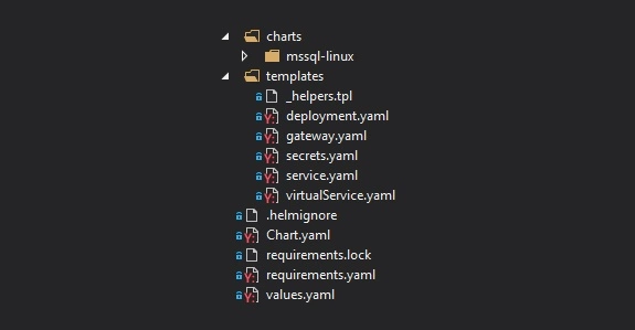
Firstly, take a look at the file structure for our chart. In the main folder, we have Chart.yaml which keeps chart metadata, requirements.yaml with which we can specify dependencies or values.yaml which serves default configuration values. In the templates folder, we can find all Kubernetes objects that will be created along with chart deployment. Then we have nested charts folder, which is a collection of charts added as a dependency in requirements.yaml. All of them will have the same file structure.
Let’s start with a focus on the deployment.yaml - a definition of Deployment controller, which provides declarative updates for Pods and Replica Sets. It is parameterized with helm templates, so you will see a lot of {{ template [...] }} in there. Definition of this Deployment itself is quite default, but we are adding a reference for the secret of SQL Server database password. We are hardcoding ‘-mssql-linux-secret’ part cause at the time of writing this article, helm doesn’t provide a straightforward way to access sub-charts properties.
env:
- name: sa_password
valueFrom:
secretKeyRef:
name: {{ template "exampleapp.name" $root }}-mssql-linux-secret
key: sapassword
As we mentioned previously, we do have SQL Server chart added as a dependency. Definition of that is pretty simple. We have to define the name of the dependency, which will match the folder name in charts subfolder and the version we want to use.
dependencies:
- name: mssql-linux
repository: https://kubernetes-charts.storage.googleapis.com
version: 0.8.0
[...]
For the mssql chart, there is one change that has to be applied in the secret.yaml . Normally, this secret will be created on each deployment ( helm upgrade ), it will generate a new sapassword - which is not what we want. The simplest way to adjust that is by modifying metadata and adding a hook on pre-install. This will guarantee that this secret will be created just once on installing the release.
metadata:
annotations:
"helm.sh/hook": "pre-install"
A deployment pipeline
Let’s focus on deployment now. We will be using Helm to install and upgrade everything that will be needed in Kubernetes. Go to the Releases pipelines on the Azure DevOps, where we will configure continuous delivery. You have to add two artifacts, one for docker image and second for charts artifact. It should look like on the image below.
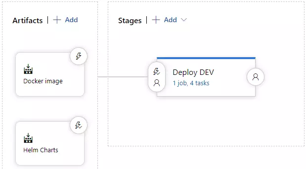
On the stages part, we could add a few more environments, which would get deployed in a similar manner, but to a different cluster. As you can see, this approach guarantees Deploy DEV stage is simply responsible for running a helm upgrade command. Before that, we need to install helm, kubectl and run helm init command.
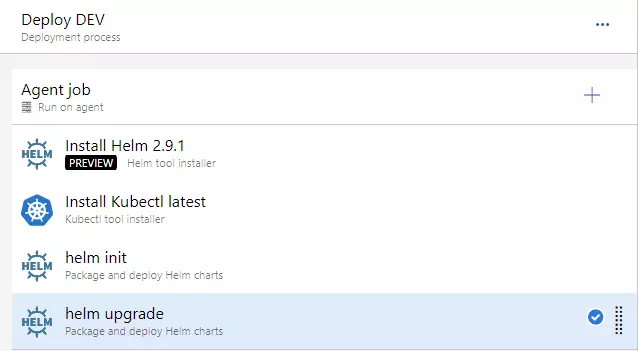
For the helm upgrade task, we need to adjust a few things.
- set Chart Path, where you can browse into Helm charts artifact (should look like: “$(System.DefaultWorkingDirectory)/Helm charts/charts”)
- paste that “image.tag=$(Build.BuildNumber)” into Set Values
- and check to Install if release not present or add --install ar argument. This will behave as helm install if release won’t exist (i.e. on a clean cluster)
At this point, we should be able to run the deployment application - you can create a release and run deployment. You should see a green output at this point :).
You can verify if the deployment went fine by running a kubectl get all command.
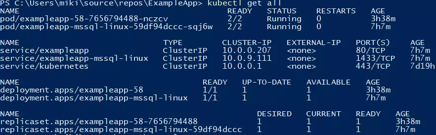
Making use of basic Istio components
Istio is a great tool, which simplifies services management. It is responsible for handling things like load balancing, traffic behavior, metric & logs, and security. Istio is leveraging Kubernetes sidecar containers, which are added to pods of our applications. You will have to enable this feature by applying an appropriate label on the namespace.
kubectl label namespace default istio-injection=enabled
All pods which will be created now will have an additional container, which is called a sidecar container in Kubernetes terms. That’s a useful feature, cause we don’t have to modify our application.
Two objects that we are using from Istio, which are part of the helm chart, are Gateway and VirtualService . For the first one, we will bring Istio definition, because it’s simple and accurate: “Gateway describes a load balancer operating at the edge of the mesh receiving incoming or outgoing HTTP/TCP connections”. That object is attached to the LoadBalancer object - we will use the one created by Istio by default. After the application is deployed, you will be able to access it using LoadBalancer external IP, which you can retrieve with such command:
kubectl get service/istio-ingressgateway -n istio-system
You can retrieve external IP from the output and verify if http://api/examples url works fine.
Summary
In this article, we have created a basic CI/CD which deploys single service into Kubernetes cluster with the help of Helm. Further adjustments can include different types of deployment, publishing tests coverage from CI or adding more services to mesh and leveraging additional Istio features. We hope you were able to complete the tutorial without any issues. Follow our blog for more in-depth articles around these topics that will be posted in the future.
Reactive service to service communication with RSocket – load balancing & resumability
This article is the second one of the mini-series which will help you to get familiar with RSocket – a new binary protocol which may revolutionize machine to machine communication in distributed systems. In the following paragraphs, we will discuss the load balancing problem in the cloud as well as we will present the resumability feature which helps to deal with network issues, especially in the IoT systems.
- If you are not familiar with RSocket basics, please see the previous article available here
- Please notice that code examples presented in the article are available at GitHub
High availability & load balancing as a crucial part of enterprise-grade systems
Applications availability and reliability are crucial parts of many business areas like banking and insurance. In these demanding industries, the services have to be operational 24/7 even during high traffic, periods of increased network latency or natural disasters. To ensure that the software is always available to the end-users it is usually deployed in redundantly, across the multiple availability zones.
In such a scenario, at least two instances of each microservice are deployed in at least two availability zones. This technique helps our system become resilient and increase its capacity - multiple instances of the microservices are able to handle a significantly higher load. So where is the trick? The redundancy introduces extra complexity. As engineers, we have to ensure that the incoming traffic is spread across all available instances. There are two major techniques which address this problem: server load balancing and client load balancing .
The first approach is based on the assumption that the requester does not know the IP addresses of the responders. Instead of that, the requester communicates with the load balancer, which is responsible for spreading the requests across the microservices connected to it. This design is fairly easy to adopt in the cloud era. IaaS providers usually have built-in, reliable solutions, like Elastic Load Balancer available in Amazon Web Services. Moreover, such a design helps develop routing strategy more sophisticated than plain round ribbon (e.g. adaptive load balancing or chained failover ). The major drawback of this technique is the fact that we have to configure and deploy extra resources, which may be painful if our system consists of hundreds of the microservices. Furthermore, it may affect the latency – each request has extra “network hop” on the load balancer.
The second technique inverts the relation. Instead of a central point used to connect to responders, the requester knows IP addresses of each and every instance of the given microservice. Having such knowledge, the client can choose the responder instance to which it sends the request or opens the connection with. This strategy does not require any extra resources, but we have to ensure that the requester has the IP addresses of all instances of the responder ( see how to deal with it using service discovery pattern ). The main benefit of the client load balancing pattern is its performance – by reduction of one extra “network hop”, we may significantly decrease the latency. This is one of the key reasons why RSocket implements the client load balancing pattern.
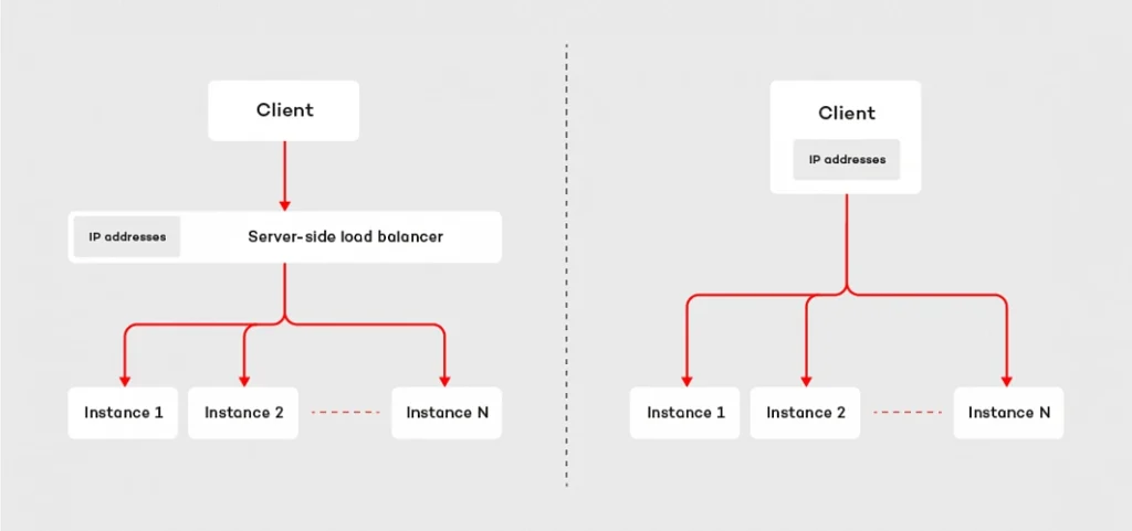
Client load balancing in RSocket
On the code level, the implementation of the client load balancing in RSocket is pretty straightforward. The mechanism relies on the LoadBalancedRSocketMono object which works as a bag of available RSocket instances, provided by RSocket supplier. To access RSockets we have to subscribe to the LoadBalancedRSocketMono which onNext signal emits fully-fledged RSocket instance. Moreover, it calculates statistics for each RSocket, so that it is able to estimate the load of each instance and based on that choose the one with the best performance at the given point of time.
The algorithm takes into account multiple parameters like latency, number of maintained connections as well as a number of pending requests. The health of each RSocket is reflected by the availability parameter – which takes values from 0 to 1, where 0 indicates that the given instance cannot handle any requests and 1 is assigned to fully operational socket. The code snippet below shows the very basic example of the load-balanced RSocket, which connects to three different instances of the responder and executes 100 requests. Each time it picks up RSocket from the LoadBalancedRSocketMono object.
@Slf4j
public class LoadBalancedClient {
static final int[] PORTS = new int[]{7000, 7001, 7002};
public static void main(String[] args) {
List rsocketSuppliers = Arrays.stream(PORTS)
.mapToObj(port -> new RSocketSupplier(() -> RSocketFactory.connect()
.transport(TcpClientTransport.create(HOST, port))
.start()))
.collect(Collectors.toList());
LoadBalancedRSocketMono balancer = LoadBalancedRSocketMono.create((Publisher>) s -> {
s.onNext(rsocketSuppliers);
s.onComplete();
});
Flux.range(0, 100)
.flatMap(i -> balancer)
.doOnNext(rSocket -> rSocket.requestResponse(DefaultPayload.create("test-request")).block())
.blockLast();
}
}
It is worth noting, that client load balancer in RSocket deals with dead connections as well. If any of the RSocket instances registered in the LoadBalancedRSocketMono stop responding, the mechanism will automatically try to reconnect. By default, it will execute 5 attempts, in 25 seconds. If it does not succeed, the given RSocket will be removed from the pool of available connections. Such design combines the advantages of the server-side load balancing with low latency and reduction of “network hops” of the client load balancing.
Dead connections & resumabilty mechanism
The question which may arise in the context of dead connections is: what will happen if I have an only single instance of the responder and the connection drops due to network issues. Is there anything we can do with this? Fortunately, RSocket has built-in resumability mechanism.
To clarify the concept let’s consider the following example. We are building an IoT platform which connects to multiple temperature sensors located in different places. Most of them in the distance to the nearest buildings and internet connection sources. Therefore, the devices connect to cloud services using GPRS. The business requirement for our system is that we need to collect temperature readings every second in the real-time, and we cannot lose any data.
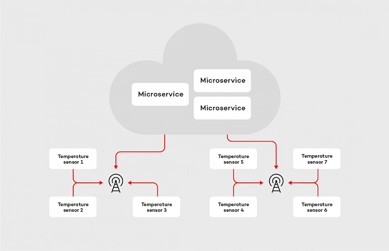
In case of the machine-to-the machine communication within the cloud, streaming data in real-time is not a big deal, but if we consider IoT devices located in areas without access to a stable, reliable internet connection, the problem becomes more complex. We can easily identify two major issues we may face in such a system: the network latency and connection stability . From a software perspective, there is not much we can do with the first one, but we can try to deal with the latter. Let’s tackle the problem with RSocket, starting with picking up the proper interaction model . The most suitable in this case is request stream method, where the microservice deployed in the cloud is the requester and temperature sensor is the responder. After choosing the interaction model we apply resumability mechanism. In RSocket, we do it by method resume() invoked on the RSocketFactory , as shown in the examples below:
@Slf4j
public class ResumableRequester {
private static final int CLIENT_PORT = 7001;
public static void main(String[] args) {
RSocket socket = RSocketFactory.connect()
.resume()
.resumeSessionDuration(RESUME_SESSION_DURATION)
.transport(TcpClientTransport.create(HOST, CLIENT_PORT))
.start()
.block();
socket.requestStream(DefaultPayload.create("dummy"))
.map(payload -> {
log.info("Received data: [{}]", payload.getDataUtf8());
return payload;
})
.blockLast();
}
}
@Slf4j
public class ResumableResponder {
private static final int SERVER_PORT = 7000;
static final String HOST = "localhost";
static final Duration RESUME_SESSION_DURATION = Duration.ofSeconds(60);
public static void main(String[] args) throws InterruptedException {
RSocketFactory.receive()
.resume()
.resumeSessionDuration(RESUME_SESSION_DURATION)
.acceptor((setup, sendingSocket) -> Mono.just(new AbstractRSocket() {
@Override
public Flux requestStream(Payload payload) {
log.info("Received 'requestStream' request with payload: [{}]", payload.getDataUtf8());
return Flux.interval(Duration.ofMillis(1000))
.map(t -> DefaultPayload.create(t.toString()));
}
}))
.transport(TcpServerTransport.create(HOST, SERVER_PORT))
.start()
.subscribe();
log.info("Server running");
Thread.currentThread().join();
}
}
The mechanism on the requester and responder side works similarly, it is based on a few components. First of all, there is a ResumableFramesStore which works as a buffer for the frames. By default, it stores them in the memory, but we can easily adjust it to our needs by implementing the ResumableFramesStore interface (e.g. store the frames in the distributed cache, like Redis). The store saves the data emitted between keep alive frames, which are sent back and forth periodically and indicates, if the connection between the peers is stable. Moreover, the keep alive frame contains the token, which determines Last received position for the requester and the responder. When the peer wants to resume the connection, it sends the resume frame with an implied position . The implied position is calculated from last received position (is the same value we have seen in the Keep Alive frame) plus the length of the frames received from that moment. This algorithm is applied to both parties of the communication, in the resume frame is it reflected by last received server position and first client available position tokens. The whole flow for resume operation is shown in the diagram below:
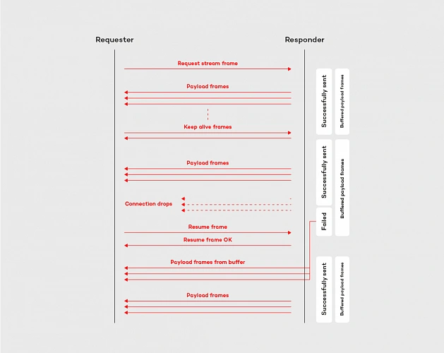
By adopting the resumability mechanism built in the RSocket protocol, with the relatively low effort we can reduce the impact of the network issues. Like shown in the example above, the resumability might be extremely useful in the data streaming applications, especially in the case of the device to the cloud communication.
Summary
In this article, we discussed more advanced features of the RSocket protocol, which are helpful in reducing the impact of the network on the system operationality. We covered the implementation of the client load balancing pattern and resumability mechanism. These features, combined with the robust interaction model constitutes the core of the protocol.
In the last article of this mini-series , we will cover available abstraction layers on top of the RSocket.
The state of DevOps – main takeaways after DOES London
DevOps is moving forward and influences various industries, changing the way companies of all sizes deliver software. Few times a year, the community of DevOps experts and practitioners gathers at a conference to discuss the latest trends, share insights, and exchange best practices. This year’s DevOps Enterprise Summit in London was one of these unique chances to participate in this uplifting movement.
When our team got back after DevOps Enterprise Summit in London, we set an engaging, internal discussion. It’s probably a common attitude for every company valuing knowledge exchange, that once attending some interesting conference, your representatives share insights, their thoughts, and news regarding the topics covered during the event. The discussion arose when members of our team had started sharing their takeaways regarding keynotes, speeches, and ideas presented at the conference.
That opened the stream of news and opinions shared by those of our teammates who also follow the latest trends in the industry by attending various meetups, listening to podcasts, etc. Here is the list of the main topics.
DevOps 2nd day – introduction
DevOps is no longer one of these innovative ideas for early adopters, which everyone has heard about but is not aware of how to start with adopting it. Now, it’s a must-have for every organization that intends to stay relevant in competitive markets. When you ask enterprises about using DevOps in their organizations, their representatives will tell you that they have already implemented this culture or are in the process of doing that. On the other hand, if you ask them if they are already satisfied with the adoption, the answer would be no – there are so many practices and principles, what makes the process demanding and it lasts a while.
Nowadays, discussions from “How to implement DevOps in our organization” have evolved into “How can we improve our DevOps practices.” The truth has been told - tech advanced companies need this agile culture to build a successful business. But simultaneously, once they introduce DevOps to their teams, new challenges occur. It’s a natural way of technology/culture adoption. As a person responsible for the cultural shift, you have to communicate it clearly – DevOps wouldn’t solve all your issues. In some cases, it may seem like a reason for some new struggles. The answer to these concerns is simple, your organization is growing, evolution is never done, and change is a constant way of managing things.
Facing DevOps 2nd Day issues is rather the rich man’s problem – you should be there, and you have to tackle them. All the new challenges appear after making an advanced step forward.
Scaling Up - from a core tech team to the entire organization working globally
Core tech teams are the first to adopt the newest solutions, but they cannot work properly without supportive teams (HR, Sales, Marketing, Accounting, etc.). After going through the successful implementation, the next step is to encourage cooperating teams to this mindset and ways of running projects.
As the enterprises that consist of thousands of employees and hundreds of teams cannot provide their crew with the flexibility in designing their very own working culture, there is a need to encourage all teams to once implemented practices.
For tech leaders, responsible for introducing DevOps in their teams, it means that their job evolves to being a DevOps advocate, who presents its value to the whole organizations and makes it a commonly known and used approach. The larger the company is the more complex the entire change becomes, but it's unavoidable when you intend to get the most out of it.
Along with advocating for expanding DevOps in the entire organization, also the very challenging job is to determine the right tech stack. New tools come and go, being responsible for selecting to the most useful toolset that will be in use for a significant period is tough and requires overall knowledge, strategy, and deep understanding of tech processes. Once determined toolset should be recommended to cooperating teams and that may provoke new issues, but is unavoidable. Should you leverage the same tech stack for all teams? When is the right time to adopt new tools? Should you leave it all to the team? Well, there is no right answer to any of these questions, and it highly depends on the situation.
DevOps is changing various industries and not limit itself to tech companies
Attending DOES in London was a great opportunity to learn more about how DevOps influences the world’s coolest companies, not often associated with technology. Let’s look at the two of the most recognized sportswear retailers - Adidas and Nike. Both these brands are synonyms to heroism, activity, sports achievements. But, as their representatives presented, both companies can overshadow many of tech brands, with their DevOps maturity and advanced approach to using technology in growing their businesses.
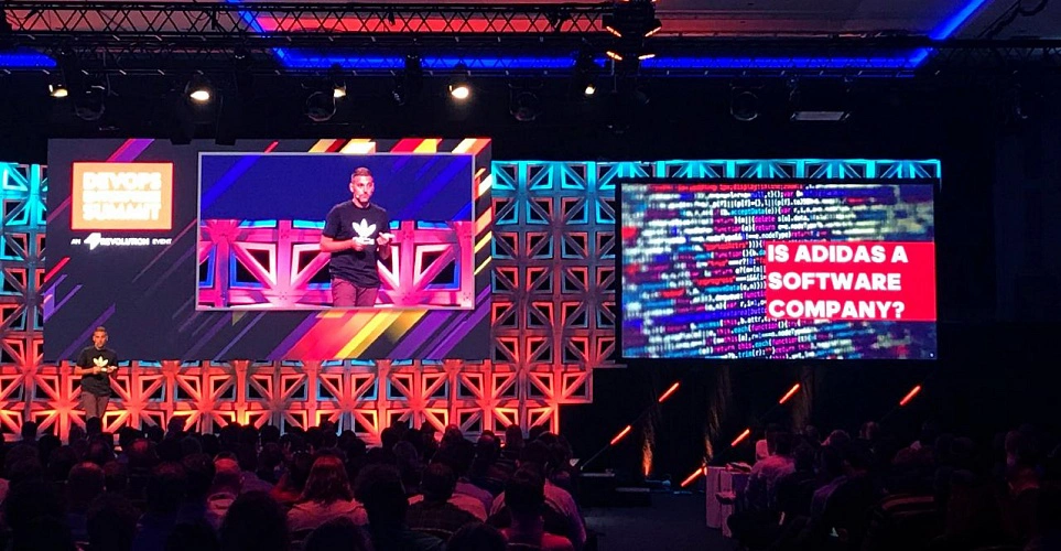
Following these business cases, we can agree that the time when cutting-edge technologies and methodologies often paired with them are limited to IT companies is officially over. Nowadays, industry by industry is convincing themselves to the latest solutions as developing software for internal processes is a natural competitive advantage.
Continuous adaptation and life-long learning
The best thing about working in a DevOps culture is that you just cannot say that the process has finished, that a company has transformed, and that a team has mastered the way of delivering software. Taking into account how creative the community gathered around DevOps is, how fast new ideas arise, how often its fundamentals are improved, you have to keep learning about new things.
It would be extremely comfortable if a company could once undergo digital transformation and treat the process as a completed. But if we take a look at the evolution of technology and methodologies designed to take full advantage of its capabilities, it’s obvious that it cannot be finished. Adoption of a DevOps mindset is the beginning of a change and should be conducted as a never-ending evolution.
You can’t be good at everything, which is fine, but you have to know your pain points
Excluding enterprises with enormous budgets, all organizations have limitations that obligate them to focus only on some aspects of conducting business processes. As an expert, a professional who works in a highly competitive market, you have to follow the latest trends, be aware of upcoming solutions, and cutting-edge technologies that are reshaping the business.
Being up to date is extremely important, but almost equally essential is the ability to decide on which things you cannot engage, as your time and resources are not flexible. Being responsible for your company means being aware of pain points and focusing only on the things that matter. Technology is developing extremely fast, you cannot afford to be an early adopter of every promising solution. Your job is to make responsible decisions, based on your deep understanding of the current state of technology development.
If you don’t know what to choose, think about what’s better for your business
DevOps came to being as an efficient solution to the common challenge - how to sync software development and IT operations processes to help companies thrive. Built with business effectiveness in mind, this culture has the right foundations. Choosing approaches that were designed to resolve not only internal issues but also to enable revenue growth is good for your overall success.
Anytime you face a situation when you have to decide between different solutions, always consider your company's long term perspective. When you are focused only on your goals, you may contribute to building siloses. The key to determine which ideas are the right to choose is their overall usability. We all, as professionals in our niches, may tend to prefer idealistic solutions. It’s important that we don’t work in an ideal world and our job is verified by the market.
Adopting new tools and technologies is challenging, but the real quest appears when it comes to change people's habits and company culture
If you want to make your colleagues angry, implement new toolset and new technologies in your team. Apart from tech freaks and beta testers, people are rather skeptical when it comes to learning new features and new UI. Things change when you provide them with solutions that make their work easier and more efficient.
But the real trouble occurs when you are trying to change your company's culture. It’s nothing new that we protect what we know, don’t want to change our habits, or even feel in danger when someone is trying to reshape the way we have been doing our job for ages. Your colleagues defend themselves which is natural, you cannot change it. You have to take this into account and make sure that the process will be smooth enough to help everyone adjust to the new reality. Start with small steps, be the example, discuss the issues, and explain potential opportunities. Shock therapy as a path to the cultural shift is not the way to go.
As a team developing our product - Cloudboostr - multicloud, enterprise-ready Kubernetes, we help companies adopt a complete cloud-native stack, built with proven patterns and best practices, so they could focus their resources on improving their working culture. The feedback we’re receiving is that our customer’s teams are more open to start using new toolset then to change the approach to software delivery.
Being a DevOps Pprofessional is hot now
DevOps practitioners are much in demand. It’s a great time to master the skills required to be a specialist in DevOps as companies of all sizes are looking for help in modernizing their businesses. There are various ways of approaching it - by building an in-house team, outsourcing processes, collaborating with external consultants. Companies choose preferred manner accordingly to their needs and budget.
No matter if you work in a dedicated team at a huge enterprise, developing startup with your colleagues, or providing consulting services for global brands, being a DevOps expert is a strong competitive advantage on the talent market.
DOES London - sum up
DevOps is moving forward and is great to be among teams that contribute to its evolution. We are willing to share our expertise , exchange knowledge, and learn from the best in the business, and conferences like DevOps Enterprise Summit are the best platforms to do it.
Reactive service to service communication with RSocket – introduction
This article is the first one of the mini-series which will help you to get familiar with RSocket – a new binary protocol which may revolutionize machine-to-machine communication. In the following paragraphs, we discuss the problems of the distributed systems and explain how these issues may be solved with RSocket. We focus on the communication between microservices and the interaction model of RSocket.
Communication problem in distributed systems
Microservices are everywhere, literally everywhere. We went through the long journey from the monolithic applications, which were terrible to deploy and maintain, to the fully distributed, tiny, scalable microservices. Such architecture design has many benefits; however, it also has drawbacks, worth mentioning. Firstly, to deliver value to the end customers, services have to exchange tons of data. In the monolithic application that was not an issue, as the entire communication occurred within a single JVM. In the microservice architecture, where services are deployed in the separate containers and communicate via an internal or external network, networking is a first-class citizen. Things get more complicated if you decide to run your applications in the cloud, where network issues and periods of increased latency is something you cannot fully avoid. Rather than trying to fix network issues, it is better to make your architecture resilient and fully operational even during a turbulent time.
Let’s dive a bit deeper into the concept of the microservices, data, communication and the cloud. As an example, we will discuss the enterprise-grade system which is accessible through a website and mobile app as well as communicates with small, external devices (e.g home heater controller). The system consists of multiple microservices, mostly written in Java and it has a few Python and node.js components. Obviously, all of them are replicated across multiple availability zones to assure that the whole system is highly available.
To be IaaS provider agnostic and improve developer experience the applications are running on top of PaaS. We have a wide range of possibilities here: Cloud Foundry, Kubernetes or both combined in Cloudboostr are suitable. In terms of communication between services, the design is simple. Each component exposes plain REST APIs – as shown in the diagram below.
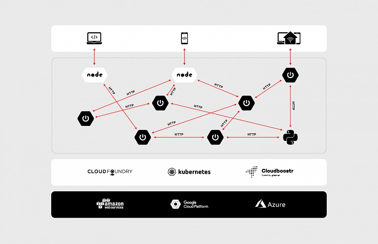
At first glance, such an architecture does not look bad. Components are separated and run in the cloud – what could go wrong? Actually, there are two major issues – both of them related to communication.
The first problem is the request/response interaction model of HTTP. While it has a lot of use cases, it was not designed for machine to machine communication. It is not uncommon for the microservice to send some data to another component without taking care about the result of the operation (fire and forget) or stream data automatically when it becomes available (data streaming). These communication patterns are hard to achieve in an elegant, efficient way using a request/response interaction model. Even performing simple fire and forget operation has side effects – the server has to send a response back to the client, even if the client is not interested in processing it.
The second problem is the performance. Let’s assume that our system is massively used by the customers, the traffic increases, and we have noticed that we are struggling to handle more than a few hundred requests per second. Thanks to the containers and the cloud, we are able to scale up our services with ease. However, if we track resource consumption a bit more, we will notice that while we are running out of memory, the CPUs of our VMs are almost idle. The issue comes from the thread per request model usually used with HTTP 1.x, where every single request has its own stack memory. In such a scenario, we can leverage the reactive programming model and non-blocking IO. It will significantly cut down memory usage, nevertheless, it will not reduce the latency. HTTP 1.x is a text-based protocol thus size of data that need to be transferred is significantly higher than in the case of binary protocols.
In the machine to machine communication we should not limit ourselves to HTTP (especially 1.x), its request/response interaction model and poor performance. There are many more suitable and robust solutions out there (on the market). Messaging based on the RabbitMQ, gRPC or even HTTP 2 with its support for multiplexing and binarized payloads will do way better in terms of performance and efficiency than plain HTTP 1.x.
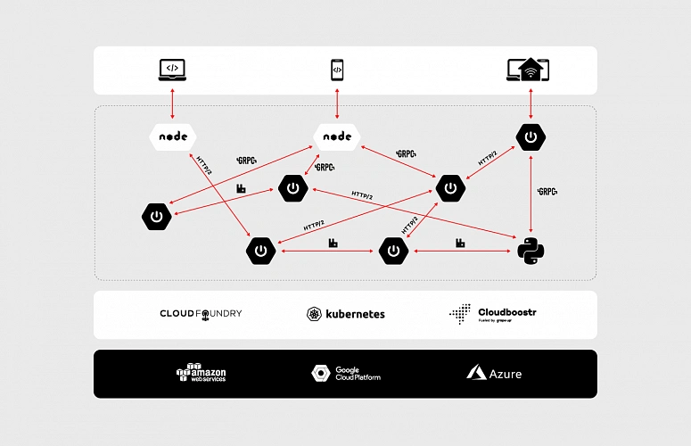
Using multiple protocols allow us to link the microservices in the most efficient and suitable way in a given scenario. However, the adoption of multiple protocols forces us to reinvent the wheel again and again. We have to enrich our data with extra information related to security and create multiple adapters which handle translation between protocols. In some cases, transportation requires external resources (brokers, services, etc.) which need to be highly available. Extra resources entail extra costs, even though all we need is simple, message-based fire and forget operation. Besides, a multitude of different protocols may introduce serious problems related to application management, especially if our system consists of hundreds of microservices.
The issues mentioned above are the core reasons why RSocket was invented and why it may revolutionize communication in the cloud. By its reactiveness and built-in robust interaction model, RSocket may be applied in various business scenarios and eventually unify the communication patterns that we use in the distributed systems.
RSocket to the rescue
RSocket is a new, message-driven, binary protocol which standardizes the approach to communication in the cloud. It helps to resolve common application concerns with a consistent manner as well as it has support for multiple languages (e.g java, js, python) and transport layers (TCP, WebSocket, Aeron).
In the following sections, we will dive deeper into protocol internals and discuss the interaction model.
Framed and message-driven
Interaction in RSocket is broken down into frames. Each frame consists of a frame header which contains the stream id, frame type definition and other data specific to the frame type. The frame header is followed by meta-data and payload – these parts carry data specified by the user.
There are multiple types of frames which represent different actions and available methods of the interaction model. We’re not going to cover all of them as they are extensively described in the official documentation (http://rsocket.io/docs/Protocol). Nevertheless, there are few which are worth noting. One of them is the Setup Frame which the client sends to the server at the very beginning of the communication. This frame can be customized so that you can add your own security rules or other information required during connection initialization. It should be noted that RSocket does not distinguish between the client and the server after the connection setup phase. Each side can start sending the data to the other one – it makes the protocol almost entirely symmetrical.
Performance
The frames are sent as a stream of bytes. It makes RSocket way more efficient than typical text-based protocols. From a developer perspective, it is easier to debug a system while JSONs are flying back and forth through the network, but the impact on the performance makes such convenience questionable. The protocol does not impose any specific serialization/deserialization mechanism, it considers the frame as a bag of bits which could be converted to anything. That makes possible to use JSON serialization or more efficient solutions like Protobuf or AVRO.
The second factor, which has a huge impact on RSocket performance is the multiplexing. The protocol creates logical streams (channels) on the top of the single physical connection. Each stream has its unique ID which, to some extent, can be interpreted as a queue we know from messaging systems. Such design deals with major issues known from HTTP 1.x – connection per request model and weak performance of “pipelining”. Moreover, RSocket natively supports transferring of the large payloads. In such a scenario the payload frame is split into several frames with an extra flag – the ordinal number of the given fragment.
Reactiveness & Flow Control
RSocket protocol fully embraces the principles stated in the Reactive Manifesto . Its asynchronous character and thrift in terms of the resources helps decrease the latency experienced by the end users and costs of the infrastructure. Thanks to streaming we don’t need to pull data from one service to another, instead, the data is pushed when it becomes available. It is an extremely powerful mechanism, but it might be risky as well. Let’s consider a simple scenario: in our system, we are streaming events from service A to service B. The action performed on the receiver side is non-trivial and require some computation time. If service A pushes events faster than B is able to process them, eventually, B will run out of resources – the sender will kill the receiver. Since RSocket uses the reactor, it has built-in support for the flow control , which helps to avoid such situations.
We can easily provide the backpressure mechanism implementation, adjusted to our needs. The receiver can specify how much data it would like to consume and will not get more than that until it notifies the sender that it is ready to process more. On the other hand, to limit the number of incoming frames from the requester, RSocket implements a lease mechanism. The responder can specify how many requests requester may send within a defined time frame.
The API
As mentioned in the previous section, RSocket uses Reactor, so that on the API level we are mainly operating on Mono and Flux objects. It has full support for reactive signals as well – we can easily implement “reaction” on different events – onNext, onError, onClose, etc.
The following paragraphs will cover the API and each and every interaction option available in RSocket. The discussion will be backed with the code snippets and the description for all the examples. Before we jump into the interaction model, it is worth describing the API basics, as it will come up in the multiple code examples.
Setting up the connection with RSocketFactory
Setting up the RSocket connection between the peers is fairly easy. The API provides factory (RSocketFactory) with factory methods receive and connect to create RSocket and CloseableChannel instances on the client and the server side respectively. Second common property present in both parties of the communication (the requester and the responder) is a transport. RSocket can use multiple solutions as a transport layer (TCP, WebSocket, Aeron). Whichever you choose the API provides the factory methods which allows you to tweak and tune the connection.
RSocketFactory.receive()
.acceptor(new HelloWorldSocketAcceptor())
.transport(TcpServerTransport.create(HOST, PORT))
.start()
.subscribe();
RSocketFactory.connect()
.transport(TcpClientTransport.create(HOST, PORT))
.start()
.subscribe();
Moreover, in the case of the responder, we have to create a socket acceptor instance. The SocketAcceptor is an interface which provides the contract between the peers. It has a single method accept which accepts the RSocket for sending requests and returns an instance of RSocket that will be used for handling the requests from the peer. Besides providing the contract the SocketAcceptor enables us to access the setup frame content. On the API level, it is reflected by ConnectionSetupPayload object.
public interface SocketAcceptor {
Mono<RSocket> accept(ConnectionSetupPayload setup, RSocket sendingSocket);
}
As shown above, setting up the connection between the peers is relatively easy, especially for those of you who worked with WebSockets previously – in terms of the API both solutions are quite similar.
Interaction model
After setting up the connection we are able to move on to the interaction model. RSocket supports following operations:
The fire and forget , as well as the metadata push , were designed to push the data from the sender to the receiver. In both scenarios the sender does not care about the result of the operation – it is reflected on API level in a return type (Mono). The difference between these actions sits in the frame. In case of fire and forget the fully-fledged frame is sent to the receiver, while for the metadata push action the frame does not have payload – it consists only of the header and the metadata. Such a lightweight message can be useful in sending notifications to the mobile or peer-to-peer communication of IoT devices.
RSocket is also able to mimic HTTP behavior. It has support for request-response semantics, and probably that will be the main type of interaction you are going to use with RSocket. In streams context, such an operation can be represented as a stream which consists of the single object. In this scenario, the client is waiting for the response frame, but it does it in a fully non-blocking manner.
More interesting in the cloud applications are the request stream and the request channel interactions which operate on the streams of data, usually infinite. In case of the request stream operation, the requester sends a single frame to the responder and gets back the stream of data. Such interaction method enables services to switch from the pull data to the push data strategy. Instead of sending periodical requests to the responder requester can subscribe to the stream and react on the incoming data – it will arrive automatically when it becomes available.
Thanks to the multiplexing and the bi-directional data transfer support, we can go a step further using the request channel method. RSocket is able to stream the data from the requester to the responder and the other way around using a single physical connection. Such interaction may be useful when the requester updates the subscription – for example, to change the subscription criteria. Without the bi-directional channel, the client would have to cancel the stream and re-request it with the new parameters.
In the API, all operations of the interaction model are represented by methods of RSocket interface shown below.
public interface RSocket extends Availability, Closeable {
Mono<Void> fireAndForget(Payload payload);
Mono<Payload> requestResponse(Payload payload);
Flux<Payload> requestStream(Payload payload);
Flux<Payload> requestChannel(Publisher<Payload> payloads);
Mono<Void> metadataPush(Payload payload);
}
To improve the developer experience and avoid the necessity of implementing every single method of the RSocket interface, the API provides abstract AbstractRSocket we can extend. By putting the SocketAcceptor and the AbstractRSocket together, we get the server-side implementation, which in the basic scenario may look like this:
@Slf4j
public class HelloWorldSocketAcceptor implements SocketAcceptor {
@Override
public Mono<RSocket> accept(ConnectionSetupPayload setup, RSocket sendingSocket) {
log.info("Received connection with setup payload: [{}] and meta-data: [{}]", setup.getDataUtf8(), setup.getMetadataUtf8());
return Mono.just(new AbstractRSocket() {
@Override
public Mono<Void> fireAndForget(Payload payload) {
log.info("Received 'fire-and-forget' request with payload: [{}]", payload.getDataUtf8());
return Mono.empty();
}
@Override
public Mono<Payload> requestResponse(Payload payload) {
log.info("Received 'request response' request with payload: [{}] ", payload.getDataUtf8());
return Mono.just(DefaultPayload.create("Hello " + payload.getDataUtf8()));
}
@Override
public Flux<Payload> requestStream(Payload payload) {
log.info("Received 'request stream' request with payload: [{}] ", payload.getDataUtf8());
return Flux.interval(Duration.ofMillis(1000))
.map(time -> DefaultPayload.create("Hello " + payload.getDataUtf8() + " @ " + Instant.now()));
}
@Override
public Flux<Payload> requestChannel(Publisher<Payload> payloads) {
return Flux.from(payloads)
.doOnNext(payload -> {
log.info("Received payload: [{}]", payload.getDataUtf8());
})
.map(payload -> DefaultPayload.create("Hello " + payload.getDataUtf8() + " @ " + Instant.now()))
.subscribeOn(Schedulers.parallel());
}
@Override
public Mono<Void> metadataPush(Payload payload) {
log.info("Received 'metadata push' request with metadata: [{}]", payload.getMetadataUtf8());
return Mono.empty();
}
});
}
}
On the sender side using the interaction model is pretty simple, all we need to do is invoke a particular method on the RSocket instance we have created using RSocketFactory, e.g.
socket.fireAndForget(DefaultPayload.create("Hello world!"));
More interesting on the sender side is the implementation of the backpressure mechanism. Let’s consider the following example of the requester side implementation:
public class RequestStream {
public static void main(String[] args) {
RSocket socket = RSocketFactory.connect()
.transport(TcpClientTransport.create(HOST, PORT))
.start()
.block();
socket.requestStream(DefaultPayload.create("Jenny", "example-metadata"))
.subscribe(new BackPressureSubscriber());
socket.dispose();
}
@Slf4j
private static class BackPressureSubscriber implements Subscriber<Payload> {
private static final Integer NUMBER_OF_REQUESTED_ITEMS = 5;
private Subscription subscription;
int receivedItems;
@Override
public void onSubscribe(Subscription s) {
this.subscription = s;
subscription.request(NUMBER_OF_REQUESTED_ITEMS);
}
@Override
public void onNext(Payload payload) {
receivedItems++;
if (receivedItems % NUMBER_OF_REQUESTED_ITEMS == 0) {
log.info("Requesting next [{}] elements", NUMBER_OF_REQUESTED_ITEMS);
subscription.request(NUMBER_OF_REQUESTED_ITEMS);
}
}
@Override
public void onError(Throwable t) {
log.error("Stream subscription error [{}]", t);
}
@Override
public void onComplete() {
log.info("Completing subscription");
}
}
}
In this example, we are requesting the stream of data, but to ensure that the incoming frames will not kill the requester we have the backpressure mechanism put in place. To implement this mechanism we use request_n frame which on the API level is reflected by the subscription.request(n) method. At the beginning of the subscription [ onSubscribe(Subscription s) ], we are requesting 5 objects, then we are counting received items in onNext(Payload payload). When all expected frames arrived to the requester, we are requesting the next 5 objects – again using subscription.request(n) method. The flow of this subscriber is shown in the diagram below:
Implementation of the backpressure mechanism presented in this section is very basic. In the production, we should provide a more sophisticated solution based on more accurate metrics e.g. predicted/average time of computation. After all, the backpressure mechanism does not make the problem of an overproducing responder disappear. It shifts the issue to the responder side, where it can be handled better. Further reading about backpressure is available here on Medium and here on GitHub .
Summary
In this article, we discuss the communication issues in the microservice architecture, and how these problems can be solved using RSocket. We covered its API and the interaction model backed with simple “hello world” example and basic backpressure mechanism implementation.
In the next articles of this series, we will cover more advanced features of RSocket including Load Balancing and Resumability as well as we will discuss abstraction over RSocke t – RPC and Spring Reactor.