Thinking out loud
Where we share the insights, questions, and observations that shape our approach.
Spring AI framework overview – introduction to AI world for Java developers
In this article, we explain the fundamentals of integrating various AI models and employing different AI-related techniques within the Spring framework. We provide an overview of the capabilities of Spring AI and discuss how to utilize the various supported AI models and tools effectively.
Understanding Spring AI - Basic concepts
Traditionally, libraries for AI integration have primarily been written in Python, making knowledge of this language essential for their use. Additionally, their integration in applications written in other languages implies the writing of a boilerplate code to communicate with the libraries. Today, Spring AI makes it easier for Java developers to enable AI in Java-based applications.
Spring AI aims to provide a unified abstraction layer for integrating various AI LLM types and techniques (e.g., ETL, embeddings, vector databases) into Spring applications. It supports multiple AI model providers, such as OpenAI, Google Vertex AI, and Azure Vector Store, through standardized interfaces that simplify their integration by abstracting away low-level details. This is achieved by offering concrete implementations tailored to each specific AI provider.
Generating data: Integration with AI models
Spring AI API supports all main types of AI models, such as chat, image, audio, and embeddings. The API for the model is consistent across all model types. It consists of the following main components:
1) Model interfaces that provide similar methods for all AI model providers. Each model type has its own specific interface, such as ChatModel for chat AI models and ImageModel for image AI models. Spring AI provides its own implementation of each interface for every supported AI model provider.
2) Input prompt/request class that is used by the AI model (via model interface) providing user input (usually text) instructions, along with options for tuning the model’s behavior.
3) Response for output data produced by the model. Depending on the model type, it contains generated text, image, or audio (for Chat Image and Audio models correspondingly) or more specific data like floating-point arrays in the case of Embedding models.
All AI model interfaces are standard Spring beans that can be injected using auto-configuration or defined in Spring Boot configuration classes.
Chat models
The chat LLMs gnerate text in response to the user’s prompts. Spring AI has the following main API for interaction with this type of model.
- The ChatModel interface allows sending a String prompt to a specific chat AI model service. For each supported AI chat model provider in Spring AI, there is a dedicated implementation of this interface.
- The prompt class contains a list of text messages (queries, typically a user input) and a ChatOptions object. The ChatOptions interface is common for all the supported AI models. Additionally, every model implementation has its own specific options for class implementation.
- The ChatResponse class encapsulates the output of the AI chat model, including a list of generated data and relevant metadata.
- Furthermore, the chat model API has a ChatClient class , which is responsible for the entire interaction with the AI model. It encapsulates the ChatModel, enabling users to build and send prompts to the model and retrieve responses from it. ChatClient has multiple options for transforming the output of the AI model, which includes converting raw text response into a custom Java object or fetching it as a Flux-based stream.
Putting all these components together, let’s give an example code of Spring service class interacting with OpenAI chat API:
// OpenAI model implementation is available via auto configuration
// when ‘org.springframework.ai:spring-ai-openai-spring-boot-starter'
// is added as a dependency
@Configurationpublic class ChatConfig {
// Defining chat client bean with OpenAI model
    @Bean
    ChatClient chatClient(ChatModel chatModel) {
return ChatClient.builder(chatModel)
.defaultSystem("Default system text")
.defaultOptions(
OpenAiChatOptions.builder()
.withMaxTokens(123)
.withModel("gpt-4-o")
.build()
).build();
}
}@Servicepublic class ChatService {
private final ChatClient chatClient;
...
public List<String> getResponses(String userInput) {
var prompt = new Prompt(
userInput,
// Specifying options of concrete AI model options
            OpenAiChatOptions.builder()
                .withTemperature(0.4)
                .build()
        );
var results = chatClient.prompt(prompt)
.call()
.chatResponse()
.getResults();
return results.stream()
.map(chatResult -> chatResult.getOutput().getContent())
.toList();
}
}
Image and Audio models
Image and Audio AI model APIs are similar to the chat model API; however, the framework does not provide a ChatClient equivalent for them.
For image models the main classes are represented by:
- ImagePrompt that contains text query and ImageOptions
- ImageModel for abstraction of the concrete AI model
- ImageResponse containing a list of the ImageGeneration objects as a result of ImageModel invocation.
Below is the example Spring service class for generating images:
@Servicepublic class ImageGenerationService {
// OpenAI model implementation is used for ImageModel via autoconfiguration
    // when ‘org.springframework.ai:spring-ai-openai-spring-boot-starter’ is
    // added as a dependency
private final ImageModel imageModel;
...
public List<Image> generateImages(String request) {
var imagePrompt = new ImagePrompt(
// Image description and prompt weight
new ImageMessage(request, 0.8f),
// Specifying options of a concrete AI model
            OpenAiImageOptions.builder()
                .withQuality("hd")
                .withStyle("natural")
                .withHeight(2048)
                .withWidth(2048)
                .withN(4)
                .build()
        );
var results = imageModel
.call(imagePrompt)
.getResults();
return results.stream()
.map(ImageGeneration::getOutput)
.toList();
}
}
When it comes to audio models there are two types of them supported by Spring AI: Transcription and Text-to-Speech.
The text-to-speech model is represented by the SpeechModel interface. It uses text query input to generate audio byte data with attached metadata.
In transcription models , there isn't a specific general abstract interface. Instead, each model is represented by a set of concrete implementations (as per different AI model providers). This set of implementations adheres to a generic "Model" interface, which serves as the root interface for all types of AI models.
Embedding models
1. The concept of embeddings
Let’s outline the theoretical concept of embeddings for a better understanding of how the embeddings API in Spring AI functions and what its purpose is.
Embeddings are numeric vectors created through deep learning by AI models. Each component of the vector corresponds to a certain property or feature of the data. This allows to define the similarities between data (like text, image or video) using mathematical operations on those vectors.
Just like 2D or 3D vectors represent a point on a plane or in a 3D space, the embedding vector represents a point in an N-dimensional space. The closer points (vectors) are to each other or, in other words, the shorter the distance between them is, the more similar the data they represent is. Mathematically the distance between vectors v1 and v2 may be defined as: sqrt(abs(v1 - v2)).
Consider the following simple example with living beings (e.g., their text description) as data and their features:
Is Animal (boolean) Size (range of 0…1) Is Domestic (boolean) Cat 1 0,1 1 Horse 1 0,7 1 Tree 0 1,0 0
In terms of the features above, the objects might be represented as the following vectors: “cat” -> [1, 0.1, 1] , “horse” -> [1, 0.7, 1] , “tree” -> [0, 1.0, 0]
For the most similar animals from our example, e.g. cat and horse, the distance between the corresponding vectors is sqrt(abs([1, 0.1, 1] - [1, 0.7, 1])) = 0,6 While comparing the most distinct objects, that is cat and tree gives us: sqrt(abs([1, 0.1, 1] - [0, 1.0, 0])) = 1,68
2. Embedding model API
The Embeddings API is similar to the previously described AI models such as ChatModel or ImageModel.
- The Document class is used for input data. The class represents an abstraction that contains document identifier, content (e.g., image, sound, text, etc), metadata, and the embedding vector associated with the content.
- The EmbeddingModel interface is used for communication with the AI model to generate embeddings. For each AI embedding model provider, there is a concrete implementation of that interface. This ensures smooth switching between various models or embedding techniques.
- The EmbeddingResponse class contains a list of generated embedding vectors.
Storing data: Vector databases
Vector databases are specifically designed to efficiently handle data in vector format. Vectors are commonly used for AI processing. Examples include vector representations of words or text segments used in chat models, as well as image pixel information or embeddings.
Spring AI has a set of interfaces and classes that allow it to interact with vector databases of various database vendors. The primary interface of this API is the VectorStore , which is designed to search for similar documents using a specific similarity query known as SearchRequest.
It also has methods for adding and removing the Document objects. When adding to the VectorStore, the embeddings for documents are typically created by the VectorStore implementation using an EmbeddingMode l. The resulting embedding vector is assigned to the documents before they are stored in the underlying vector database.
Below is an example of how we can retrieve and store the embeddings using the input documents using the Azure AI Vector Store.
@Configurationpublic class VectorStoreConfig {
...
@Bean
public VectorStore vectorStore(EmbeddingModel embeddingModel) {
var searchIndexClient = ... //get azure search index client
return new AzureVectorStore(
searchIndexClient,
embeddingModel,
true,
 // Metadata fields to be used for the similarity search
            // Considering documents that are going to be stored in vector store
            // represent books/book descriptions
            List.of(MetadataField.date("yearPublished"),
                MetadataField.text("genre"),
                MetadataField.text("author"),
                MetadataField.int32("readerRating"),
                MetadataField.int32("numberOfMainCharacters")));
    }
}
@Service
public class EmbeddingService {
private final VectorStore vectorStore;
...
public void save(List<Document> documents) {
 // The implementation of VectorStore uses EmbeddingModel to get embedding vector
        // for each document, sets it to the document object and then stores it
        vectorStore.add(documents);
    }
public List<Document> findSimilar(String query,
double similarityLimit,
                                      Filter.Expression filter) {
return vectorStore.similaritySearch(
SearchRequest.query(query) // used for embedding similarity search
// only having equal or higher similarity
.withSimilarityThreshold(similarityLimit)
// search only documents matching filter criteria
                .withFilterExpression(filter)
                .withTopK(10)
// max number of results
        );
    }
public List<Document> findSimilarGoodFantasyBook(String query) {
var goodFantasyFilterBuilder = new FilterExpressionBuilder();
var goodFantasyCriteria = goodFantasyFilterBuilder.and(
goodFantasyFilterBuilder.eq("genre", "fantasy"),
goodFantasyFilterBuilder.gte("readerRating", 9)
).build();
return findSimilar(query, 0.9, goodFantasyCriteria);
}
}
Preparing data: ETL pipelines
The ETL, which stands for “Extract, Transform, Load” is a process of transforming raw input data (or documents) to make it applicable or more efficient for the further processing by AI models. As the name suggests, the ETL consists of three main stages: extracting the raw data from various data sources, transforming data into a structured format, and storing the structured data in the database.
In Spring AI the data used for ETL in every stage is represented by the Document class mentioned earlier. Here are the Spring AI components representing each stage in ETL pipeline:
- DocumentReader – used for data extraction, implements Supplier<List<Document>>
- DocumentTransformer – used for transformation, implements Function<List<Document>, List<Document>>
- DocumentWriter – used for data storage, implements Consumer<List<Document>>
The DocumentReader interface has a separate implementation for each particular document type, e.g., JsonReader, TextReader, PagePdfDocumentReader, etc. Readers are temporary objects and are usually created in a place where we need to retrieve the input data, just like, e.g., InputStream objects. It is also worth mentioning that all the classes are designed to get their input data as a Resource object in their constructor parameter. And, while Resource is abstract and flexible enough to support various data sources, such an approach limits the reader class capabilities as it implies conversion of any other data sources like Stream to the Resource object.
The DocumentTransformer has the following implementations:
- TokenTextSplitter – splits document into chunks using CL100K_BASE encoding, used for preparing input context data of AI model to fit the text into the model’s context window.
- KeywordMetadataEnricher – uses a generative AI model for getting the keywords from the document and embeds them into the document’s metadata.
- SummaryMetadataEnricher – enriches the Document object with its summary generated by a generative AI model.
- ContentFormatTransformer – applies a specified ContentFormatter to each document to unify the format of the documents.
These transformers cover some of the most popular use cases of data transformation. However, if some specific behavior is required, we’ll have to provide a custom DocumentTransformer.
When it comes to the DocumentWriter , there are two main implementations: VectorStore, mentioned earlier, and FileDocumentWriter, which writes the documents into a single file. For real-world development scenarios the VectorStore seems the most suitable option. FileDocumentWriter is more suitable for simple or demo software where we don't want or need a vector database.
With all the information provided above, here is a clear example of what a simple ETL pipeline looks like when written using Spring AI:
public void saveTransformedData() {
// Get resource e.g. using InputStreamResource
    Resource textFileResource = ...
    TextReader textReader = new TextReader(textFileResource);
   // Assume tokenTextSplitter instance in created as bean in configuration
    // Note that the read() and split() methods return List<Document> objects
    vectorStore.write(tokenTextSplitter.split(textReader.read()));
}
It is worth mentioning that the ETL API uses List<Document> only to transfer data between readers, transformers, and writers. This may limit their usage when the input document set is large, as it requires the loading of all the documents in memory at once.
Converting data: Structured output
While the output of AI models is usually raw data like text, image, or sound, in some cases, we may benefit from structuring that data. Particularly when the response includes a description of an object with features or properties that suggest an implicit structure within the output.
Spring AI offers a Structured Output API designed for chat models to transform raw text output into structured objects or collections. This API operates in two main steps: first, it provides the AI model with formatting instructions for the input data, and second, it converts the model's output (which is already formatted according to these instructions) into a specific object type. Both the formatting instructions and the output conversion are handled by implementations of the StructuredOutputConverter interface.
There are three converters available in Spring AI:
- BeanOutputConverter<T> – instructs AI model to produce JSON output using JSON Schema of a specified class and converts it to the instances of the that class as an output.
- MapOutputConverter – instructs AI model to produce JSON output and parses it into a Map<String, Object> object
- ListOutputConverter – retrieves comma separated items form AI model creating a List<String> output
Below is an example code for generating a book info object using BeanOutputConverter:
public record BookInfo (String title,
String author,
int yearWritten,
int readersRating) { }

@Service
public class BookService {
private final ChatClient chatClient;
// Created in configuration of BeanOutputConverter<BookInfo> typeBookInfo> type
private final StructuredOutputConverter<BookInfo> bookInfoConverter;
...
public final BookInfo findBook() {
return chatClient.prompt()
.user(promptSpec ->
promptSpec
.text("Generate description of the best " +
"fantasy book written by {author}.")
.param("author", "John R. R. Tolkien"))
.call()
.entity(bookInfoConverter);
}
}
Production Readiness
To evaluate the production readiness of the Spring AI framework, let’s focus on the aspects that have an impact on its stability and maintainability.
Spring AI is a new framework. The project was started back in 2023. The first publicly available version, the 0.8.0 one, was released in February 2024. There were 6 versions released in total (including pre-release ones) during this period of time.
It’s an official framework of Spring Projects, so the community developing it should be comparable to other frameworks, like Spring JPA. If the framework development continues, it’s expected that the community will provide support on the same level as for other Spring-related frameworks.
The latest version, 1.0.0-M4, published in November, is still a release candidate/milestone. The development velocity, however, is quite good. Framework is being actively developed: according to the GitHub statistics, the commit rate is 5.2 commits per day, and the PR rate is 3.5 PRs per day. We may see it by comparing it to some older, well-developed frameworks, such as Spring Data JPA, which has 1 commit per day and 0.3 PR per day accordingly.
When it comes to bug fixing, there are about 80 bugs in total, with 85% of them closed on their official GitHub page. Since the project is quite new, these numbers may not be as representable as in other older Spring projects. For example, Spring Data JPA has almost 800 bugs with about 90% fixed.
Conclusion
Overall, the Spring AI framework looks very promising. It might become a game changer for AI-powered Java applications because of its integration with Spring Boot framework and the fact that it covers the vast majority of modern AI model providers and AI-related tools, wrapping them into abstract, generic, easy-to-use interfaces.

Ragas and Langfuse integration - quick guide and overview
With large language models (LLMs) being used in a variety of applications today, it has become essential to monitor and evaluate their responses to ensure accuracy and quality. Effective evaluation helps improve the model's performance and provides deeper insights into its strengths and weaknesses. This article demonstrates how embeddings and LLM services can be used to perform end-to-end evaluations of an LLM's performance and send the resulting metrics as traces to Langfuse for monitoring.
This integrated workflow allows you to evaluate models against predefined metrics such as response relevance and correctness and visualize these metrics in Langfuse, making your models more transparent and traceable. This approach improves performance monitoring while simplifying troubleshooting and optimization by turning complex evaluations into actionable insights.
I will walk you through the setup, show you code examples, and discuss how you can scale and improve your AI applications with this combination of tools.
To summarize, we will explore the role of Ragas in evaluating the LLM model and how Langfuse provides an efficient way to monitor and track AI metrics.
Important : For this article, Ragas in version 0.1.21 and Python 3.12 were used.
If you would like to migrate to version 0.2.+ follow, then up the latest release documentation.
1. What is Ragas, and what is Langfuse?
1.1 What is Ragas?
So, what’s this all about? You might be wondering: "Do we really need to evaluate what a super-smart language model spits out? Isn’t it already supposed to be smart?" Well, yes, but here’s the deal: while LLMs are impressive, they aren’t perfect. Sometimes, they give great responses, and other times… not so much. We all know that with great power comes great responsibility. That’s where Ragas steps in.
Think of Ragas as your model’s personal coach . It keeps track of how well the model is performing, making sure it’s not just throwing out fancy-sounding answers but giving responses that are helpful, relevant, and accurate. The main goal? To measure and track your model's performance, just like giving it a score - without the hassle of traditional tests.
1.2 Why bother evaluating?
Imagine your model as a kid in a school. It might answer every question, but sometimes it just rambles, says something random, or gives you that “I don’t know” look in response to a tricky question. Ragas makes sure that your LLM isn’t just trying to answer everything for the sake of it. It evaluates the quality of each response, helping you figure out where the model is nailing it and where it might need a little more practice.
In other words, Ragas provides a comprehensive evaluation by allowing developers to use various metrics to measure LLM performance across different criteria , from relevance to factual accuracy. Moreover, it offers customizable metrics, enabling developers to tailor the evaluation to suit specific real-world applications.
1.3 What is Langfuse, and how can I benefit from it?
Langfuse is a powerful tool that allows you to monitor and trace the performance of your language models in real-time. It focuses on capturing metrics and traces, offering insights into your models' performance. With Langfuse, you can track metrics such as relevance, correctness, or any custom evaluation metric generated by tools like Ragas and visualize them to better understand your model's behavior.
In addition to tracing and metrics, Langfuse also offers options for prompt management and fine-tuning (non-self-hosted versions), enabling you to track how different prompts impact performance and adjust accordingly. However, in this article, I will focus on how tracing and metrics can help you gain better insights into your model’s real-world performance.
2. Combining Ragas and Langfuse
2.1 Real-life setup
Before diving into the technical analysis, let me provide a real-life example of how Ragas and Langfuse work together in an integrated system. This practical scenario will help clarify the value of this combination and how it applies in real-world applications, offering a clearer perspective before we jump into the code.
Imagine using this setup in a customer service chatbot , where every user interaction is processed by an LLM. Ragas evaluates the answers generated based on various metrics, such as correctness and relevance, while Langfuse tracks these metrics in real-time. This kind of integration helps improve chatbot performance, ensuring high-quality responses while also providing real-time feedback to developers.
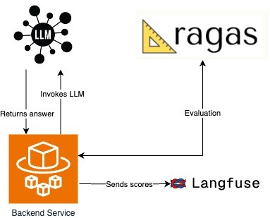
In my current setup, the backend service handles all the interactions with the chatbot. Whenever a user sends a message, the backend processes the input and forwards it to the LLM to generate a response. Depending on the complexity of the question, the LLM may invoke external tools or services to gather additional context before formulating its answer. Once the LLM returns the answer, the Ragas framework evaluates the quality of the response.
After the evaluation, the backend service takes the scores generated by Ragas and sends them to Langfuse. Langfuse tracks and visualizes these metrics, enabling real-time monitoring of the model's performance, which helps identify improvement areas and ensures that the LLM maintains an elevated level of accuracy and quality during conversations.
This architecture ensures a continuous feedback loop between the chatbot, the LLM, and Ragas while providing insight into performance metrics via Langfuse for further optimization.
2.2 Ragas setup
Here’s where the magic happens. No great journey is complete without a smooth, well-designed API. In this setup, the API expects to receive the essential elements: question, context, expected contexts, answer, and expected answer. But why is it structured this way? Let me explain.
- The question in our API is the input query you want the LLM to respond to, such as “What is the capital of France?” It's the primary element that triggers the model's reasoning process. The model uses this question to generate a relevant response based on its training data or any additional context provided.
- The answer is the output generated by the LLM, which should directly respond to the question. For example, if the question is “What is the capital of France?” the answer would be “The capital of France is Paris.” This is the model's attempt to provide useful information based on the input question.
- The expected answer represents the ideal response. It serves as a reference point to evaluate whether the model’s generated answer was correct. So, if the model outputs "Paris," and the expected answer was also "Paris," the evaluation would score this as a correct response. It's like the answer key for a test.
- Context is where things get more interesting. It's the additional information the model can use to craft its answer. Imagine asking the question, “What were Albert Einstein’s contributions to science?” Here, the model might pull context from an external document or reference text about Einstein’s life and work. Context gives the model a broader foundation to answer questions that need more background knowledge.
- Finally, the expected context is the reference material we expect the model to use. In our Einstein example, this could be a biographical document outlining his theory of relativity. We use the expected context to compare and see if the model is basing its answers on the correct information.
After outlining the core elements of the API, it’s important to understand how Retrieval-Augmented Generation (RAG) enhances the language model’s ability to handle complex queries. RAG combines the strength of pre-trained language models with external knowledge retrieval systems. When the LLM encounters specialized or niche queries, it fetches relevant data or documents from external sources, adding depth and context to its responses. The more complex the query, the more critical it is to provide detailed context that can guide the LLM to retrieve relevant information. In my example, I used a simplified context, which the LLM managed without needing external tools for additional support.
In this Ragas setup, the evaluation is divided into two categories of metrics: those that require ground truth and those where ground truth is optional . These distinctions shape how the LLM’s performance is evaluated.
Metrics that require ground truth depend on having a predefined correct answer or expected context to compare against. For example, metrics like answer correctness and context recall evaluate whether the model’s output closely matches the known, correct information. This type of metric is essential when accuracy is paramount, such as in customer support or fact-based queries. If the model is asked, "What is the capital of France?" and it responds with "Paris," the evaluation compares this to the expected answer, ensuring correctness.
On the other hand, metrics where ground truth is optional - like answer relevancy or faithfulness - don’t rely on direct comparison to a correct answer. These metrics assess the quality and coherence of the model's response based on the context provided, which is valuable in open-ended conversations where there might not be a single correct answer. Instead, the evaluation focuses on whether the model’s response is relevant and coherent within the context it was given.
This distinction between ground truth and non-ground truth metrics impacts evaluation by offering flexibility depending on the use case. In scenarios where precision is critical, ground truth metrics ensure the model is tested against known facts. Meanwhile, non-ground truth metrics allow for assessing the model’s ability to generate meaningful and coherent responses in situations where a definitive answer may not be expected. This flexibility is vital in real-world applications, where not all interactions require perfect accuracy but still demand high-quality, relevant outputs.
And now, the implementation part:
from typing import Optional

from fastapi import FastAPI
from pydantic import BaseModel

from src.service.ragas_service import RagasEvaluator


class QueryData(BaseModel):
   question: Optional[str] = None
   contexts: Optional[list[str]] = None
   expected_contexts: Optional[list[str]] = None
   answer: Optional[str] = None
   expected_answer: Optional[str] = None


class EvaluationAPI:
   def __init__(self, app: FastAPI):
       self.app = app
       self.add_routes()

   def add_routes(self):
       @self.app.post("/api/ragas/evaluate_content/")
       async def evaluate_answer(data: QueryData):
           evaluator = RagasEvaluator()
           result = evaluator.process_data(
               question=data.question,
               contexts=data.contexts,
               expected_contexts=data.expected_contexts,
               answer=data.answer,
               expected_answer=data.expected_answer,
           )
           return result
Now, let’s talk about configuration. In this setup, embeddings are used to calculate certain metrics in Ragas that require a vector representation of text, such as measuring similarity and relevancy between the model’s response and the expected answer or context. These embeddings provide a way to quantify the relationship between text inputs for evaluation purposes.
The LLM endpoint is where the model generates its responses. It’s accessed to retrieve the actual output from the model, which Ragas then evaluates. Some metrics in Ragas depend on the output generated by the model, while others rely on vectorized representations from embeddings to perform accurate comparisons.
import json
import logging
from typing import Any, Optional

import requests

from datasets import Dataset
from langchain_openai.chat_models import AzureChatOpenAI
from langchain_openai.embeddings import AzureOpenAIEmbeddings
from ragas import evaluate
from ragas.metrics import (
   answer_correctness,
   answer_relevancy,
   answer_similarity,
   context_entity_recall,
   context_precision,
   context_recall,
   faithfulness,
)
from ragas.metrics.critique import coherence, conciseness, correctness, harmfulness, maliciousness

from src.config.config import Config

logging.basicConfig(level=logging.INFO)
logger = logging.getLogger(__name__)


class RagasEvaluator:
   azure_model: AzureChatOpenAI
   azure_embeddings: AzureOpenAIEmbeddings


   def __init__(self) -> None:
       config = Config()
       self.azure_model = AzureChatOpenAI(
           openai_api_key=config.api_key,
           openai_api_version=config.api_version,
           azure_endpoint=config.api_endpoint,
           azure_deployment=config.deployment_name,
           model=config.embedding_model_name,
           validate_base_url=False,
       )
       self.azure_embeddings = AzureOpenAIEmbeddings(
           openai_api_key=config.api_key,
           openai_api_version=config.api_version,
           azure_endpoint=config.api_endpoint,
           azure_deployment=config.embedding_model_name,
       )
The logic in the code is structured to separate the evaluation process into different metrics, which allows flexibility in measuring specific aspects of the LLM’s responses based on the needs of the scenario. Ground truth metrics come into play when the LLM’s output needs to be compared against a known, correct answer or context. For instance, metrics like answer correctness or context recall check if the model’s response aligns with what was expected. The run_individual_evaluations function manages these evaluations by verifying if both the expected answer and context are available for comparison.
On the other hand, non-ground truth metrics are used when there isn’t a specific correct answer to compare against. These metrics, such as faithfulness and answer relevancy, assess the overall quality and relevance of the LLM’s output. The collect_non_ground_metrics and run_non_ground_evaluation functions manage this type of evaluation by examining characteristics like coherence, conciseness, or harmfulness without needing a predefined answer. This split ensures that the model’s performance can be evaluated comprehensively in various situations.
def process_data(
       self,
       question: Optional[str] = None,
       contexts: Optional[list[str]] = None,
       expected_contexts: Optional[list[str]] = None,
       answer: Optional[str] = None,
       expected_answer: Optional[str] = None,
) -> Optional[dict[str, Any]]:
   results: dict[str, Any] = {}
   non_ground_metrics: list[Any] = []

   # Run individual evaluations that require specific ground_truth
   results.update(self.run_individual_evaluations(question, contexts, answer, expected_answer, expected_contexts))

   # Collect and run non_ground evaluations
   non_ground_metrics.extend(self.collect_non_ground_metrics(contexts, question, answer))
   results.update(self.run_non_ground_evaluation(question, contexts, answer, non_ground_metrics))


   return {"metrics": results} if results else None
def run_individual_evaluations(
       self,
       question: Optional[str],
       contexts: Optional[list[str]],
       answer: Optional[str],
       expected_answer: Optional[str],
       expected_contexts: Optional[list[str]],
) -> dict[str, Any]:
   logger.info("Running individual evaluations with question: %s, expected_answer: %s", question, expected_answer)
   results: dict[str, Any] = {}

   # answer_correctness, answer_similarity
   if expected_answer and answer:
       logger.info("Evaluating answer correctness and similarity")
       results.update(
           self.evaluate_with_metrics(
               metrics=[answer_correctness, answer_similarity],
               question=question,
               contexts=contexts,
               answer=answer,
               ground_truth=expected_answer,
           )
       )

   # expected_context
   if question and expected_contexts and contexts:
       logger.info("Evaluating context precision")
       results.update(
           self.evaluate_with_metrics(
               metrics=[context_precision],
               question=question,
               contexts=contexts,
               answer=answer,
               ground_truth=self.merge_ground_truth(expected_contexts),
           )
       )

   # context_recall
   if expected_answer and contexts:
       logger.info("Evaluating context recall")
       results.update(
           self.evaluate_with_metrics(
               metrics=[context_recall],
               question=question,
               contexts=contexts,
               answer=answer,
               ground_truth=expected_answer,
           )
       )

   # context_entity_recall
   if expected_contexts and contexts:
       logger.info("Evaluating context entity recall")
       results.update(
           self.evaluate_with_metrics(
               metrics=[context_entity_recall],
               question=question,
               contexts=contexts,
               answer=answer,
               ground_truth=self.merge_ground_truth(expected_contexts),
           )
       )

   return results
def collect_non_ground_metrics(
       self, context: Optional[list[str]], question: Optional[str], answer: Optional[str]
) -> list[Any]:
   logger.info("Collecting non-ground metrics")
   non_ground_metrics: list[Any] = []

   if context and answer:
       non_ground_metrics.append(faithfulness)
   else:
       logger.info("faithfulness metric could not be used due to missing context or answer.")

   if question and answer:
       non_ground_metrics.append(answer_relevancy)
   else:
       logger.info("answer_relevancy metric could not be used due to missing question or answer.")

   if answer:
       non_ground_metrics.extend([harmfulness, maliciousness, conciseness, correctness, coherence])
   else:
       logger.info("aspect_critique metric could not be used due to missing answer.")

   return non_ground_metrics
def run_non_ground_evaluation(
       self,
       question: Optional[str],
       contexts: Optional[list[str]],
       answer: Optional[str],
       non_ground_metrics: list[Any],
) -> dict[str, Any]:
   logger.info("Running non-ground evaluations with metrics: %s", non_ground_metrics)
   if non_ground_metrics:
       return self.evaluate_with_metrics(
           metrics=non_ground_metrics,
           question=question,
           contexts=contexts,
           answer=answer,
           ground_truth="",  # Empty as non_ground metrics do not require specific ground_truth
       )
   return {}
@staticmethod
def merge_ground_truth(ground_truth: Optional[list[str]]) -> str:
   if isinstance(ground_truth, list):
       return " ".join(ground_truth)
   return ground_truth or ""

class RagasEvaluator:
   azure_model: AzureChatOpenAI
   azure_embeddings: AzureOpenAIEmbeddings

   langfuse_url: str
   langfuse_public_key: str
   langfuse_secret_key: str

   def __init__(self) -> None:
       config = Config()
       self.azure_model = AzureChatOpenAI(
           openai_api_key=config.api_key,
           openai_api_version=config.api_version,
           azure_endpoint=config.api_endpoint,
           azure_deployment=config.deployment_name,
           model=config.embedding_model_name,
           validate_base_url=False,
       )
       self.azure_embeddings = AzureOpenAIEmbeddings(
           openai_api_key=config.api_key,
           openai_api_version=config.api_version,
           azure_endpoint=config.api_endpoint,
           azure_deployment=config.embedding_model_name,
       )
2.3 Langfuse setup
To use Langfuse locally, you'll need to create both an organization and a project in your self-hosted instance after launching via Docker Compose. These steps are necessary to generate the public and secret keys required for integrating with your service. The keys will be used for authentication in your API requests to Langfuse's endpoints, allowing you to trace and monitor evaluation scores in real-time. The official documentation provides detailed instructions on how to get started with a local deployment using Docker Compose, which can be found here .
The integration is straightforward: you simply use the keys in the API requests to Langfuse’s endpoints, enabling real-time performance tracking of your LLM evaluations.
Let me present integration with Langfuse:
class RagasEvaluator:

   # previous code from above
   langfuse_url: str
   langfuse_public_key: str
   langfuse_secret_key: str

   def __init__(self) -> None:

       # previous code from above
       self.langfuse_url = "http://localhost:3000"
       self.langfuse_public_key = "xxx"
       self.langfuse_secret_key = "yyy"def send_scores_to_langfuse(self, trace_id: str, scores: dict[str, Any]) -> None:
   """
   Sends evaluation scores to Langfuse via the /api/public/scores endpoint.
   """
   url = f"{self.langfuse_url}/api/public/scores"
   auth_string = f"{self.langfuse_public_key}:{self.langfuse_secret_key}"
   auth_bytes = base64.b64encode(auth_string.encode('utf-8')).decode('utf-8')

   headers = {
       "Content-Type": "application/json",
       "Authorization": f"Basic {auth_bytes}"
   }
   # Iterate over scores and send each one
   for score_name, score_value in scores.items():
       payload = {
           "traceId": trace_id,
           "name": score_name,
           "value": score_value,
       }

       logger.info("Sending score to Langfuse: %s", payload)
       response = requests.post(url, headers=headers, data=json.dumps(payload))
And the last part is to invoke that function in process_data. Simply just add:
if results:
   trace_id = "generated-trace-id"
   self.send_scores_to_langfuse(trace_id, results)
3. Test and results
Let's use the URL endpoint below to start the evaluation process:
http://0.0.0.0:3001/api/ragas/evaluate_content/
Here is a sample of the input data:
{
"question": "Did Gomez know about the slaughter of the Fire Mages?",
"answer": "Gomez, the leader of the Old Camp, feigned ignorance about the slaughter of the Fire Mages. Despite being responsible for ordering their deaths to tighten his grip on the Old Camp, Gomez pretended to be unaware to avoid unrest among his followers and to protect his leadership position.",
"expected_answer": "Gomez knew about the slaughter of the Fire Mages, as he ordered it to consolidate his power within the colony. However, he chose to pretend that he had no knowledge of it to avoid blame and maintain control over the Old Camp.",
"contexts": [
"{\"Gomez feared the growing influence of the Fire Mages, believing they posed a threat to his control over the Old Camp. To secure his leadership, he ordered the slaughter of the Fire Mages, though he later denied any involvement.\"}",
"{\"The Fire Mages were instrumental in maintaining the barrier that kept the colony isolated. Gomez, in his pursuit of power, saw them as an obstacle and thus decided to eliminate them, despite knowing their critical role.\"}",
"{\"Gomez's decision to kill the Fire Mages was driven by a desire to centralize his authority. He manipulated the events to make it appear as though he was unaware of the massacre, thus distancing himself from the consequences.\"}"
],
"expected_context": "Gomez ordered the slaughter of the Fire Mages to solidify his control over the Old Camp. However, he later denied any involvement to distance himself from the brutal event and avoid blame from his followers."
}
And here is the result presented in Langfuse
Results: {'answer_correctness': 0.8177382234142327, 'answer_similarity': 0.9632605859646228, 'context_recall': 1.0, 'faithfulness': 0.8333333333333334, 'answer_relevancy': 0.9483433866761223, 'harmfulness': 0.0, 'maliciousness': 0.0, 'conciseness': 1.0, 'correctness': 1.0, 'coherence': 1.0}
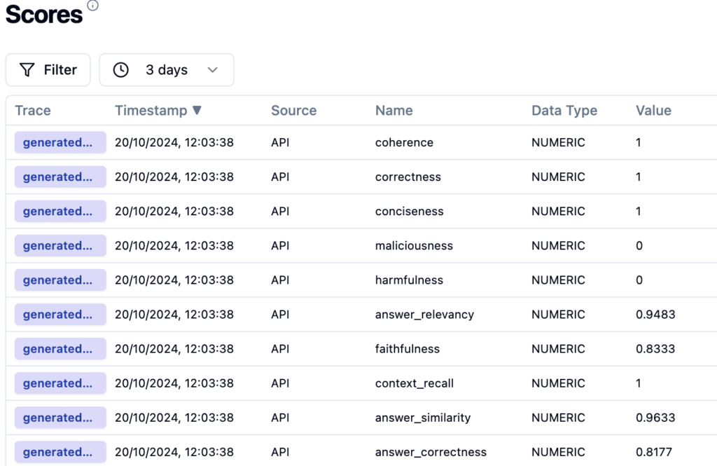
As you can see, it is as simple as that.
4. Summary
In summary, I have built an evaluation system that leverages Ragas to assess LLM performance through various metrics. At the same time, Langfuse tracks and monitors these evaluations in real-time, providing actionable insights. This setup can be seamlessly integrated into CI/CD pipelines for continuous testing and evaluation of the LLM during development, ensuring consistent performance.
Additionally, the code can be adapted for more complex LLM workflows where external context retrieval systems are integrated. By combining this with real-time tracking in Langfuse, developers gain a robust toolset for optimizing LLM outputs in dynamic applications. This setup not only supports live evaluations but also facilitates iterative improvement of the model through immediate feedback on its performance.
However, every rose has its thorn. The main drawbacks of using Ragas include the costs and time associated with the separate API calls required for each evaluation. This can lead to inefficiencies, especially in larger applications with many requests. Ragas can be implemented asynchronously to improve performance, allowing evaluations to occur concurrently without blocking other processes. This reduces latency and makes more efficient use of resources.
Another challenge lies in the rapid pace of development in the Ragas framework. As new versions and updates are frequently released, staying up to date with the latest changes can require significant effort. Developers need to continuously adapt their implementation to ensure compatibility with the newest releases, which can introduce additional maintenance overhead.

How to migrate on-premise databases to AWS RDS with AWS DMS: Our guide
Migrating an on-premise MS SQL Server database to AWS RDS, especially for high-stakes applications handling sensitive information, can be challenging yet rewarding. This guide walks through the rationale for moving to the cloud, the key steps, the challenges you may face, and the potential benefits and risks.
Why Cloud?
When undertaking such a significant project, you might wonder why we would change something that was working well. Why shift from a proven on-premise setup to the cloud? It's a valid question. The rise in the popularity of cloud technology is no coincidence, and AWS offers several advantages that make the move worthwhile for us.
First, AWS's global reach and availability play a crucial role in choosing it. AWS operates in multiple regions and availability zones worldwide, allowing applications to deploy closer to users, reducing latency, and ensuring higher availability. In case of any issues at one data center, AWS's ability to automatically switch to another ensures minimal downtime - a critical factor, especially for our production environment.
Another significant reason for choosing AWS is the fully managed nature of AWS RDS . In an on-premise setup, you are often responsible for everything from provisioning to scaling, patching, and backing up the database. With AWS, these responsibilities are lifted. AWS takes care of backups, software patching, and even scaling based on demand, allowing the team to focus more on application development and less on infrastructure management.
Cost is another compelling factor. AWS's pay-as-you-go model eliminates the need to over-provision hardware, as is often done on-premise to handle peak loads. By paying only for resources used, particularly in development and testing environments, expenses are significantly reduced. Resources can be scaled up or down as needed, especially beneficial during periods of lower activity.
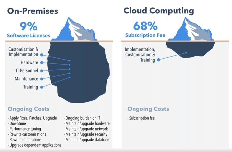
Source: https://www.peoplehr.com/blog/2015/06/12/saas-vs-on-premise-hr-systems-pros-cons-hidden-costs/
The challenges and potential difficulties
Migrating a database from on-premise to AWS RDS isn’t a simple task, especially when dealing with multiple environments like dev, UAT, staging, preprod, and production. Here are some of the possible issues that could arise during the process:
- Complexity of the migration process : Migrating on-premise databases to AWS RDS involves several moving parts, from initial planning to execution. The challenge is not just about moving the data but ensuring that all dependencies, configurations, and connections between the database and applications remain intact. This requires a deep understanding of our infrastructure and careful planning to avoid disrupting production systems.
The complexity could increase with the need to replicate different environments - each with its unique configurations - without introducing inconsistencies. For example, the development environment might allow more flexibility, but production requires tight controls for security and reliability.
- Data consistency and minimal downtime : Ensuring data consistency while minimizing downtime for a production environment might be one of the toughest aspects. For a business that operates continuously, even a few minutes of downtime could affect customers and operations. Although AWS DMS (Database Migration Service) supports live data replication to help mitigate downtime, careful timing of the migration might be necessary to avoid conflicts or data loss. Inconsistent data, even for a brief period, could lead to application failures or incorrect reports.
Additionally, setting up the initial full load of data followed by ongoing change data capture (CDC) could present a challenge. Close migration monitoring might be essential to ensure no changes are missed while data is being transferred.
- Handling legacy systems : Some existing systems might not be fully compatible with cloud-native features, requiring certain services to be rewritten to work in synchronous or asynchronous manners to avoid potential timeout issues within an organization’s applications.
- Security and compliance considerations : Security is a major concern throughout the migration process, especially when moving sensitive business data to the cloud. AWS offers robust security tools, but it’s necessary to ensure that everything is correctly configured to avoid potential vulnerabilities. This included setting up IAM roles, policies, and firewalls and managing infrastructure with relevant tools. Additionally, a secure connection between on-premise and cloud databases would likely be crucial to safeguard data migration using AWS DMS.
- Managing the learning curve : For a team relatively new to AWS, the learning curve can be steep. AWS offers a vast array of services and features, each with its own set of best practices, pricing models, and configuration options. Learning to use services like RDS, DMS, IAM, and CloudWatch effectively could require time and experimentation with various configurations to optimize performance.
- Coordination across teams : Migrating such a critical part of the infrastructure requires coordination across multiple teams - development, operations, security, and management. Each team has its priorities and concerns, making smooth communication and alignment of goals a potential challenge to ensure a unified approach.

What can be gained by migrating on-premise databases to AWS RDS
This journey isn’t fast or easy. So, is it worth it? Absolutely! The migration to AWS RDS provides significant benefits for database management. With the ability to scale databases up or down based on demand, performance is optimized, and over-provisioning resources is avoided. AWS RDS automates manual backups and database maintenance, allowing teams to focus on more strategic tasks. Additionally, the pay-as-you-go model helps manage and optimize costs more efficiently.
Risks and concerns
AWS is helpful and can make your work easier. However, it's important to be aware of the potential risks:
- Vendor lock-in : Once you’re deep into AWS services, moving away can be difficult due to the reliance on AWS-specific technologies and configurations.
- Security misconfigurations : While AWS provides strong security tools, a misconfiguration can expose sensitive data. It’s crucial to ensure access controls, encryption, and monitoring are set up correctly.
- Unexpected costs : While AWS’s pricing can be cost-effective, it’s easy to incur unexpected costs, especially if you don’t properly monitor your resource usage or optimize your infrastructure.
Conclusion
Migrating on-premise databases to AWS RDS using AWS DMS is a learning experience. The cloud offers incredible opportunities for scalability, flexibility, and innovation, but it also requires a solid understanding of best practices to fully benefit from it. For organizations considering a similar migration, the key is to approach it with careful planning, particularly around data consistency, downtime minimization, and security.
For those just starting with AWS, don't be intimidated - AWS provides extensive documentation, and the community is always there to help. By embracing the cloud, we open the door to a more agile, scalable, and resilient future.

EU Data regulations decoded: Expert solutions for IoT compliance and growth
IoT manufacturers are continuously advancing the potential of connected devices. By 2025, the global expansion of IoT is projected to generate nearly 80 zettabytes of data annually (1), highlighting the immense scale and complexity of managing this volume.
However, with innovation comes the challenge of navigating Europe’s regulatory landscape .
Three key EU data regulations – the Data Governance Act (DGA) (2), the EU Data Act (3), and the General Data Protection Regulation (GDPR) (4) – outline how businesses must handle, share, and protect both personal and non-personal data.
This article explains how these regulations work together and how IoT manufacturers can comply while opening new business opportunities within this legal framework.
Explaining the EU Data Act
The EU Data Act, set to be fully implemented in 2025, seeks to ensure fairness and transparency in the data economy. It gives users and businesses the right to access and control data generated by IoT devices , promoting innovation and fair competition.
- User control over data : The EU Data Act allows users (and businesses) to authorize the sharing of their device-generated data with third-party service providers. This requires IoT manufacturers to build systems that enable users to easily request and manage access to their data.
- Mandatory data sharing : In certain cases, IoT manufacturers will be required to share data with other businesses when authorized by the user. For example, third-party service providers may need access to this data. In B2B scenarios, manufacturers can request reasonable compensation for providing the data.
This regulation is particularly relevant in industries like automotive and smart cities, where multiple stakeholders rely on shared data. A connected car manufacturer, for instance, must ensure users can authorize access to their vehicle data for services like maintenance or insurance.
Introduction to the Data Governance Act
The DGA, effective since September 2023, is all about creating a trustworthy, neutral data-sharing system. It focuses on two key areas: data intermediation services and data altruism .
- Access to public sector data: The DGA allows businesses to reuse data from public sector bodies, such as healthcare, transportation, and environmental data. This provides access to high-quality data that can be used to develop new products, services, and innovations.
Example: A company developing AI-based healthcare solutions can use anonymized public health data to create more accurate models or treatments.
- Data intermediation services : Intermediaries are neutral third parties that help exchange data between IoT manufacturers and other data users (like third-party service providers) under B2B, C2B, and data cooperative models.
The idea emerged as an alternative to big tech platforms monopolizing data-sharing. The goal? To provide a secure and transparent space where personal and non-personal data can be shared safely.
Example: A smart home manufacturer might team up with a data intermediary to help users share energy data with utility companies or researchers looking into energy efficiency.
Manufacturers cannot act as intermediaries directly, but they can partner with or establish separate entities to manage data exchanges. If they create these intermediaries, the entities must function independently from the core business. This separation ensures data is handled fairly and transparently without commercial bias.
The goal is to build trust - intermediaries are only there to facilitate secure, neutral connections between data holders and users without using the data for their own benefit.
- Data altruism : This is all about voluntary data sharing for the public good. Think research or environmental projects. IoT manufacturers can give users the option to donate their data, opening the door to collaborations with research bodies or public organizations.
The DGA's core focus is building user trust by ensuring data transparency, security, and fairness, whether through neutral intermediaries or data shared for a greater cause.
Key GDPR rules every business should know
The GDPR, in effect since 2018, sets strict rules for how businesses collect, store, and process personal data, including data from IoT devices.
- User consent and transparency : IoT manufacturers must obtain explicit user consent before collecting or processing personal data, such as health data from wearable devices or location data from connected cars. Transparency about how this data is used is also required.
- Data security and privacy : Manufacturers must implement robust security measures to protect personal data and adhere to data minimization principles - only collecting what’s necessary. Additionally, they must uphold user rights, such as providing access to their data, supporting data portability, and allowing users to request erasure (the right to be forgotten).
For example, wearable device manufacturers need to ensure the security of personal data and offer users the ability to request the deletion of their data if they no longer wish for it to be stored.
How the DGA, EU Data Act, and GDPR work together
These three EU data regulations create a well-rounded framework for managing both personal and non-personal data in the IoT space.
- The DGA : The Data Governance Act creates neutral, secure data-sharing ecosystems, promoting transparency and fairness when multiple parties exchange data through trusted intermediaries.
- The EU Data Act : This regulation complements the DGA by giving users control over the data generated by their devices, allowing them to request that it be shared with third-party service providers. In certain B2B cases, the data holder may request fair compensation for providing access to the data.
- The GDPR : The GDPR adds strong protections for personal data. When personal information is involved, it ensures that users’ privacy and rights are respected.
Example:
Imagine a smart agriculture company that manufactures sensors to monitor soil and weather conditions.
Under the DGA, the company can work with neutral intermediaries to securely share aggregated environmental data with researchers studying climate change, maintaining transparency and fairness in the exchange.
At the same time, the EU Data Act allows farmers who use these sensors to maintain control over their data and request that it be shared with third-party services like equipment manufacturers or crop analytics firms. In certain B2B cases, the smart agriculture company can ask for fair compensation for sharing aggregated data insights.
If personal data is involved - such as specific information about a farm or farmer - the GDPR governs how this data is processed and shared, requiring user consent and protecting the farmer’s privacy throughout the process.
How IoT manufacturers adapt to EU data regulations
Implement robust data protection measures: Secure personal data with strong encryption, access controls, and anonymization. Obtain explicit user consent, ensure compliance with access and erasure requests, and support data portability. Processes for timely responses to data requests and identity verification are crucial.
Build systems for data access and sharing: Create mechanisms for users to easily share or revoke access to their data and establish clear frameworks for data sharing with third parties, including compensation rules where appropriate. Ensure these practices align with competition laws.
Partner with or create independent data intermediaries: Collaborate with neutral data intermediaries to handle data exchanges between parties securely and without bias or create an independent entity within your organization to fulfill this role, following the EU Data Governance Act’s guidelines.
Adopt privacy-by-design principles : Integrate privacy and security measures into the design phase of your products and services. This means designing IoT devices and platforms with built-in security and privacy features, such as anonymization, data minimization, and encryption, from the outset rather than adding these measures later.
Focus on data interoperability and standardization: Adopt standardized data formats to ensure that your IoT devices and platforms can communicate and exchange data seamlessly with other systems. This not only helps with regulatory compliance but also avoids vendor lock-in and enhances competitiveness by allowing your products to integrate more easily with third-party services.
The role of an IT enabler in navigating EU data regulatory landscape
Given today’s complex regulatory landscape, IoT manufacturers need a technology partner to stay compliant and create business opportunities. An IT enabler provides the tools, expertise, and infrastructure to help companies meet legal and compliance EU data regulations requirements efficiently. Here are the key areas where you’ll need support:
- Regulatory compliance : Navigating complex frameworks requires a deep understanding of these regulations to ensure legal obligations are met. An IT enabler helps interpret laws, builds compliance-focused solutions, and keeps your business up to date with evolving regulations.
- Technology solutions : To comply with privacy laws, businesses must implement secure data handling, processing, and sharing systems. Your IT partner offers scalable technology solutions to manage and protect personal and non-personal data.
- Data exchanges : IoT manufacturers must enable secure, compliant data exchanges with external partners, including neutral data intermediaries and third-party services. An IT enabler designs and implements systems to facilitate these data exchanges while also ensuring transparency and fairness.
- Operational simplicity : Compliance with regulations should not burden your core operations. An IT partner simplifies regulatory processes through automation, effective governance, and streamlined workflows.
- Ongoing maintenance and updates : Once solutions are built and implemented, they require ongoing maintenance to comply with new laws and standards. A software development consultancy provides long-term support and regular updates to ensure your systems evolve alongside regulatory changes.
- Customizable solutions : Every IoT manufacturer has unique business needs, and regulatory compliance often depends on industry-specific nuances. An sofwtare development consulting partner can develop custom-built solutions that not only meet legal standards but also align with your specific operational and business goals.
- Integration with existing systems : Rather than replacing your entire IT infrastructure, an IT enabler integrates new compliance solutions with your existing systems, ensuring a smooth transition with minimal disruption.
At Grape Up , we provide the solutions, expertise, and long-term support to help you navigate these challenges and stay ahead in the regulatory landscape.
Need guidance on complex EU data regulations? We offer expert consulting to guide you.
Looking for secure data-sharing platforms? Our products ensure safe exchanges with third parties while keeping your business compliant.
Whether it’s managing compliance, data security, or third-party integrations, we provide the tools and expertise to support your needs.
.......................
Source:
- https://www.researchgate.net/figure/nternet-of-Things-IoT-connected-devices-from-2015-to-2025-in-billions_fig1_325645304#:~:text=1%2C%20By%20the%20year%202025,of%2079%20zettabytes%20%5B12%5D%20.
- https://digital-strategy.ec.europa.eu/en/policies/data-governance-act
- https://digital-strategy.ec.europa.eu/en/policies/data-act
- https://gdpr-info.eu/


Android AAOS 14 - EVS network camera
The automotive industry has been rapidly evolving with technological advancements that enhance the driving experience and safety. Among these innovations, the Android Automotive Operating System (AAOS) has stood out, offering a versatile and customizable platform for car manufacturers.
The Exterior View System (EVS) is a comprehensive camera-based system designed to provide drivers with real-time visual monitoring of their vehicle's surroundings. It typically includes multiple cameras positioned around the vehicle to eliminate blind spots and enhance situational awareness, significantly aiding in maneuvers like parking and lane changes. By integrating with advanced driver assistance systems, EVS contributes to increased safety and convenience for drivers.
For more detailed information about EVS and its configuration, we highly recommend reading our article "Android AAOS 14 - Surround View Parking Camera: How to Configure and Launch EVS (Exterior View System)." This foundational article provides essential insights and instructions that we will build upon in this guide.
The latest Android Automotive Operating System , AAOS 14, presents new possibilities, but it does not natively support Ethernet cameras. In this article, we describe our implementation of an Ethernet camera integration with the Exterior View System (EVS) on Android.
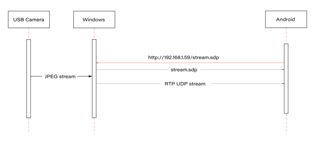
Our approach involves connecting a USB camera to a Windows laptop and streaming the video using the Real-time Transport Protocol (RTP). By employing the powerful FFmpeg software, the video stream will be broadcast and described in an SDP (Session Description Protocol) file, accessible via an HTTP server. On the Android side, we'll utilize the FFmpeg library to receive and decode the video stream, effectively bringing the camera feed into the AAOS 14 environment.
This article provides a step-by-step guide on how we achieved this integration of the EVS network camera, offering insights and practical instructions for those looking to implement a similar solution. The following diagram provides an overview of the entire process:
Building FFmpeg Library for Android
To enable RTP camera streaming on Android, the first step is to build the FFmpeg library for the platform. This section describes the process in detail, using the ffmpeg-android-maker project. Follow these steps to successfully build and integrate the FFmpeg library with the Android EVS (Exterior View System) Driver.
Step 1: Install Android SDK
First, install the Android SDK. For Ubuntu/Debian systems, you can use the following commands:
sudo apt update && sudo apt install android-sdk
The SDK should be installed in /usr/lib/android-sdk .
Step 2: Install NDK
Download the Android NDK (Native Development Kit) from the official website:
https://developer.android.com/ndk/downloads
After downloading, extract the NDK to your desired location.
Step 3: Build FFmpeg
Clone the ffmpeg-android-maker repository and navigate to its directory:
git clone https://github.com/Javernaut/ffmpeg-android-maker.gitcd ffmpeg-android-maker
Set the environment variables to point to the SDK and NDK:
export ANDROID_SDK_HOME=/usr/lib/android-sdk
export ANDROID_NDK_HOME=/path/to/ndk/
Run the build script:
./ffmpeg-android-maker.sh
This script will download FFmpeg source code and dependencies, and compile FFmpeg for various Android architectures.
Step 4: Copy Library Files to EVS Driver
After the build process is complete, copy the .so library files from build/ffmpeg/ to the EVS Driver directory in your Android project:
cp build/ffmpeg/*.so /path/to/android/project/packages/services/Car/cpp/evs/sampleDriver/aidl/
Step 5: Add Libraries to EVS Driver Build Files
Edit the Android.bp file in the aidl directory to include the prebuilt FFmpeg libraries:
cc_prebuilt_library_shared {
    name: "rtp-libavcodec",
    vendor: true,
    srcs: ["libavcodec.so"],
    strip: {
        none: true,
    },
    check_elf_files: false,
}

cc_prebuilt_library {
    name: "rtp-libavformat",
    vendor: true,
    srcs: ["libavformat.so"],
    strip: {
        none: true,
    },
    check_elf_files: false,
}

cc_prebuilt_library {
    name: "rtp-libavutil",
    vendor: true,
    srcs: ["libavutil.so"],
    strip: {
        none: true,
    },
    check_elf_files: false,
}

cc_prebuilt_library_shared {
    name: "rtp-libswscale",
    vendor: true,
    srcs: ["libswscale.so"],
    strip: {
        none: true,
    },
    check_elf_files: false,
}
Add prebuilt libraries to EVS Driver app:
cc_binary {
    name: "android.hardware.automotive.evs-default",
    defaults: ["android.hardware.graphics.common-ndk_static"],
    vendor: true,
    relative_install_path: "hw",
    srcs: [
        ":libgui_frame_event_aidl",
        "src/*.cpp"
    ],
    shared_libs: [
        "rtp-libavcodec",
       	"rtp-libavformat",
       	"rtp-libavutil",
       	"rtp-libswscale",
        "android.hardware.graphics.bufferqueue@1.0",
        "android.hardware.graphics.bufferqueue@2.0",
        android.hidl.token@1.0-utils,

....]
}
By following these steps, you will have successfully built the FFmpeg library for Android and integrated it into the EVS Driver.
EVS Driver RTP Camera Implementation
In this chapter, we will demonstrate how to quickly implement RTP support for the EVS (Exterior View System) driver in Android AAOS 14. This implementation is for demonstration purposes only. For production use, the implementation should be optimized, adapted to specific requirements, and all possible configurations and edge cases should be thoroughly tested. Here, we will focus solely on displaying the video stream from RTP.
The main files responsible for capturing and decoding video from USB cameras are implemented in the EvsV4lCamera and VideoCapture classes. To handle RTP, we will copy these classes and rename them to EvsRTPCamera and RTPCapture . RTP handling will be implemented in RTPCapture . We need to implement four main functions:
bool open(const char* deviceName, const int32_t width = 0, const int32_t height = 0);
void close();
bool startStream(std::function<void(RTPCapture*, imageBuffer*, void*)> callback = nullptr);
void stopStream();
We will use the official example from the FFmpeg library, https://github.com/FFmpeg/FFmpeg/blob/master/doc/examples/demux_decode.c, which decodes the specified video stream into RGBA buffers. After adapting the example, the RTPCapture.cpp file will look like this:
#include "RTPCapture.h"
#include <android-base/logging.h>

#include <errno.h>
#include <error.h>
#include <fcntl.h>
#include <memory.h>
#include <stdio.h>
#include <stdlib.h>
#include <sys/ioctl.h>
#include <sys/mman.h>
#include <unistd.h>

#include <cassert>
#include <iomanip>
#include <stdio.h>
#include <stdlib.h>
#include <iostream>
#include <fstream>
#include <sstream>

static AVFormatContext *fmt_ctx = NULL;
static AVCodecContext *video_dec_ctx = NULL, *audio_dec_ctx;
static int width, height;
static enum AVPixelFormat pix_fmt;

static enum AVPixelFormat out_pix_fmt = AV_PIX_FMT_RGBA;

static AVStream *video_stream = NULL, *audio_stream = NULL;
static struct SwsContext *resize;
static const char *src_filename = NULL;

static uint8_t *video_dst_data[4] = {NULL};
static int video_dst_linesize[4];
static int video_dst_bufsize;

static int video_stream_idx = -1, audio_stream_idx = -1;
static AVFrame *frame = NULL;
static AVFrame *frame2 = NULL;
static AVPacket *pkt = NULL;
static int video_frame_count = 0;

int RTPCapture::output_video_frame(AVFrame *frame)
{
    LOG(INFO) << "Video_frame: " << video_frame_count++
              << " ,scale height: " << sws_scale(resize, frame->data, frame->linesize, 0, height, video_dst_data, video_dst_linesize);
if (mCallback) {
imageBuffer buf;
        buf.index = video_frame_count;
        buf.length = video_dst_bufsize;
        mCallback(this, &buf, video_dst_data[0]);
    }

    return 0;
}

int RTPCapture::decode_packet(AVCodecContext *dec, const AVPacket *pkt)
{
    int ret = 0;

    ret = avcodec_send_packet(dec, pkt);
    if (ret < 0) {
        return ret;
    }

    // get all the available frames from the decoder
    while (ret >= 0) {
        ret = avcodec_receive_frame(dec, frame);
        if (ret < 0) {
            if (ret == AVERROR_EOF || ret == AVERROR(EAGAIN))
            {
                return 0;
            }
            return ret;
        }

        // write the frame data to output file
        if (dec->codec->type == AVMEDIA_TYPE_VIDEO) {
            ret = output_video_frame(frame);
        }

        av_frame_unref(frame);
        if (ret < 0)
            return ret;
    }

    return 0;
}

int RTPCapture::open_codec_context(int *stream_idx,
                              AVCodecContext **dec_ctx, AVFormatContext *fmt_ctx, enum AVMediaType type)
{
    int ret, stream_index;
    AVStream *st;
    const AVCodec *dec = NULL;

    ret = av_find_best_stream(fmt_ctx, type, -1, -1, NULL, 0);
    if (ret < 0) {
        fprintf(stderr, "Could not find %s stream in input file '%s'\n",
                av_get_media_type_string(type), src_filename);
        return ret;
    } else {
        stream_index = ret;
        st = fmt_ctx->streams[stream_index];

        /* find decoder for the stream */
        dec = avcodec_find_decoder(st->codecpar->codec_id);
        if (!dec) {
            fprintf(stderr, "Failed to find %s codec\n",
                    av_get_media_type_string(type));
            return AVERROR(EINVAL);
        }

        /* Allocate a codec context for the decoder */
        *dec_ctx = avcodec_alloc_context3(dec);
        if (!*dec_ctx) {
            fprintf(stderr, "Failed to allocate the %s codec context\n",
                    av_get_media_type_string(type));
            return AVERROR(ENOMEM);
        }

        /* Copy codec parameters from input stream to output codec context */
        if ((ret = avcodec_parameters_to_context(*dec_ctx, st->codecpar)) < 0) {
            fprintf(stderr, "Failed to copy %s codec parameters to decoder context\n",
                    av_get_media_type_string(type));
            return ret;
        }

        av_opt_set((*dec_ctx)->priv_data, "preset", "ultrafast", 0);
        av_opt_set((*dec_ctx)->priv_data, "tune", "zerolatency", 0);

        /* Init the decoders */
        if ((ret = avcodec_open2(*dec_ctx, dec, NULL)) < 0) {
            fprintf(stderr, "Failed to open %s codec\n",
                    av_get_media_type_string(type));
            return ret;
        }
        *stream_idx = stream_index;
    }

    return 0;
}

bool RTPCapture::open(const char* /*deviceName*/, const int32_t /*width*/, const int32_t /*height*/) {
    LOG(INFO) << "RTPCapture::open";

    int ret = 0;
    avformat_network_init();

    mFormat = V4L2_PIX_FMT_YUV420;
    mWidth = 1920;
    mHeight = 1080;
    mStride = 0;

    /* open input file, and allocate format context */
    if (avformat_open_input(&fmt_ctx, "http://192.168.1.59/stream.sdp", NULL, NULL) < 0) {
        LOG(ERROR) << "Could not open network stream";
        return false;
    }
    LOG(INFO) << "Input opened";

    isOpened = true;

    /* retrieve stream information */
    if (avformat_find_stream_info(fmt_ctx, NULL) < 0) {
        LOG(ERROR) << "Could not find stream information";
        return false;
    }
    LOG(INFO) << "Stream info found";

    if (open_codec_context(&video_stream_idx, &video_dec_ctx, fmt_ctx, AVMEDIA_TYPE_VIDEO) >= 0) {
        video_stream = fmt_ctx->streams[video_stream_idx];

        /* allocate image where the decoded image will be put */
        width = video_dec_ctx->width;
        height = video_dec_ctx->height;
        pix_fmt = video_dec_ctx->sw_pix_fmt;

        resize = sws_getContext(width, height, AV_PIX_FMT_YUVJ422P,
                                width, height, out_pix_fmt, SWS_BICUBIC, NULL, NULL, NULL);

        LOG(ERROR) << "RTPCapture::open pix_fmt: " << video_dec_ctx->pix_fmt
                   << ", sw_pix_fmt: " << video_dec_ctx->sw_pix_fmt
                   << ", my_fmt: " << pix_fmt;

        ret = av_image_alloc(video_dst_data, video_dst_linesize,
                             width, height, out_pix_fmt, 1);

        if (ret < 0) {
            LOG(ERROR) << "Could not allocate raw video buffer";
            return false;
        }
        video_dst_bufsize = ret;
    }

    av_dump_format(fmt_ctx, 0, src_filename, 0);

    if (!audio_stream && !video_stream) {
        LOG(ERROR) << "Could not find audio or video stream in the input, aborting";
        ret = 1;
        return false;
    }

    frame = av_frame_alloc();
    if (!frame) {
        LOG(ERROR) << "Could not allocate frame";
        ret = AVERROR(ENOMEM);
        return false;
    }
    frame2 = av_frame_alloc();

    pkt = av_packet_alloc();
    if (!pkt) {
        LOG(ERROR) << "Could not allocate packet";
        ret = AVERROR(ENOMEM);
        return false;
    }

    return true;
}

void RTPCapture::close() {
    LOG(DEBUG) << __FUNCTION__;
}

bool RTPCapture::startStream(std::function<void(RTPCapture*, imageBuffer*, void*)> callback) {
    LOG(INFO) << "startStream";
    if(!isOpen()) {
        LOG(ERROR) << "startStream failed. Stream not opened";
        return false;
    }

    stop_thread_1 = false;
    mCallback = callback;
    mCaptureThread = std::thread([this]() { collectFrames(); });

    return true;
}

void RTPCapture::stopStream() {
    LOG(INFO) << "stopStream";
    stop_thread_1 = true;
    mCaptureThread.join();
    mCallback = nullptr;
}

bool RTPCapture::returnFrame(int i) {
    LOG(INFO) << "returnFrame" << i;
    return true;
}

void RTPCapture::collectFrames() {
    int ret = 0;

    LOG(INFO) << "Reading frames";
    /* read frames from the file */
    while (av_read_frame(fmt_ctx, pkt) >= 0) {
        if (stop_thread_1) {
            return;
        }

        if (pkt->stream_index == video_stream_idx) {
            ret = decode_packet(video_dec_ctx, pkt);
        }
        av_packet_unref(pkt);
        if (ret < 0)
            break;
    }
}

int RTPCapture::setParameter(v4l2_control&) {
    LOG(INFO) << "RTPCapture::setParameter";
    return 0;
}

int RTPCapture::getParameter(v4l2_control&) {
    LOG(INFO) << "RTPCapture::getParameter";
    return 0;
}

std::set<uint32_t> RTPCapture::enumerateCameraControls() {
    LOG(INFO) << "RTPCapture::enumerateCameraControls";
    std::set<uint32_t> ctrlIDs;
    return std::move(ctrlIDs);
}

void* RTPCapture::getLatestData() {
    LOG(INFO) << "RTPCapture::getLatestData";
    return nullptr;
}

bool RTPCapture::isFrameReady() {
    LOG(INFO) << "RTPCapture::isFrameReady";
    return true;
}

void RTPCapture::markFrameConsumed(int i) {
    LOG(INFO) << "RTPCapture::markFrameConsumed frame: " << i;
}

bool RTPCapture::isOpen() {
    LOG(INFO) << "RTPCapture::isOpen";
    return isOpened;
}
Next, we need to modify EvsRTPCamera to use our RTPCapture class instead of VideoCapture . In EvsRTPCamera.h , add:
#include "RTPCapture.h"
And replace:
VideoCapture mVideo = {};
with:
RTPCapture mVideo = {};
In EvsRTPCamera.cpp , we also need to make changes. In the forwardFrame(imageBuffer* pV4lBuff, void* pData) function, replace:
mFillBufferFromVideo(bufferDesc, (uint8_t*)targetPixels, pData, mVideo.getStride());
with:
memcpy(targetPixels, pData, pV4lBuff->length);
This is because the VideoCapture class provides a buffer from the camera in various YUYV pixel formats. The mFillBufferFromVideo function is responsible for converting the pixel format to RGBA. In our case, RTPCapture already provides an RGBA buffer. This is done in the
int RTPCapture::output_video_frame(AVFrame *frame) function using sws_scale from the FFmpeg library.
Now we need to ensure that our RTP camera is recognized by the system. The EvsEnumerator class and its enumerateCameras function are responsible for detecting cameras. This function adds all video files from the /dev/ directory.
To add our RTP camera, we will append the following code at the end of the enumerateCameras function:
if (addCaptureDevice("rtp1")) {
    ++captureCount;
}
This will add a camera with the ID "rtp1" to the list of detected cameras, making it visible to the system.
The final step is to modify the EvsEnumerator: :openCamera function to direct the camera with the ID "rtp1" to the RTP implementation. Normally, when opening a USB camera, an instance of the EvsV4lCamera class is created:
pActiveCamera = EvsV4lCamera::Create(id.data());
In our example, we will hardcode the ID check and create the appropriate object:
if (id == "rtp1") {
    pActiveCamera = EvsRTPCamera::Create(id.data());
} else {
    pActiveCamera = EvsV4lCamera::Create(id.data());
}
With this implementation, our camera should start working. Now we need to build the EVS Driver application and push it to the device along with the FFmpeg libraries:
mmma packages/services/Car/cpp/evs/sampleDriver/
adb push out/target/product/rpi4/vendor/bin/hw/android.hardware.automotive.evs-default /vendor/bin/hw/
Launching the RTP Camera
To stream video from your camera, you need to install FFmpeg ( https://www.ffmpeg.org/download.html#build-windows ) and an HTTP server on the computer that will be streaming the video.
Start FFmpeg (example on Windows):
ffmpeg -f dshow -video_size 1280x720 -i video="USB Camera" -c copy -f rtp rtp://192.168.1.53:8554
where:
- -video_size is video resolution
- "USB Camera" is the name of the camera as it appears in the Device Manager
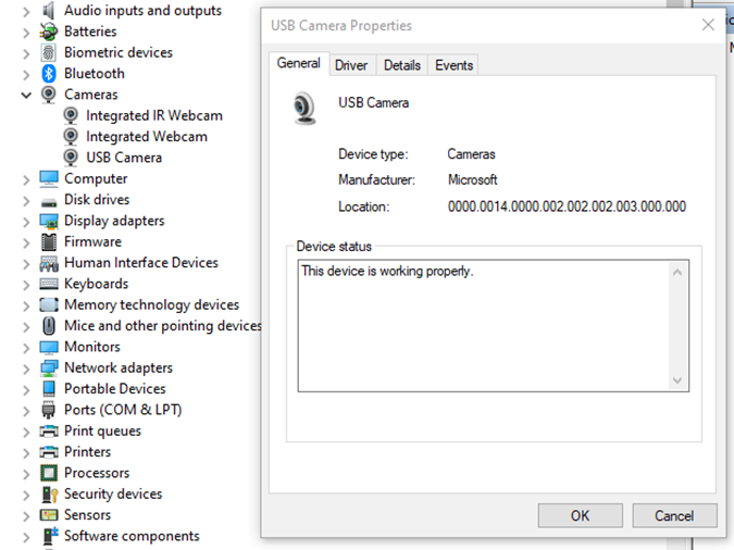
- "-c copy" means that individual frames from the camera (in JPEG format) will be copied to the RTP stream without changes. Otherwise, FFmpeg would need to decode and re-encode the image, introducing unnecessary delays.
- "rtp://192.168.1.53:8554": 192.168.1.53 is the IP address of our Android device. You should adjust this accordingly. Port 8554 can be left as the default.
After starting FFmpeg, you should see output similar to this on the console:
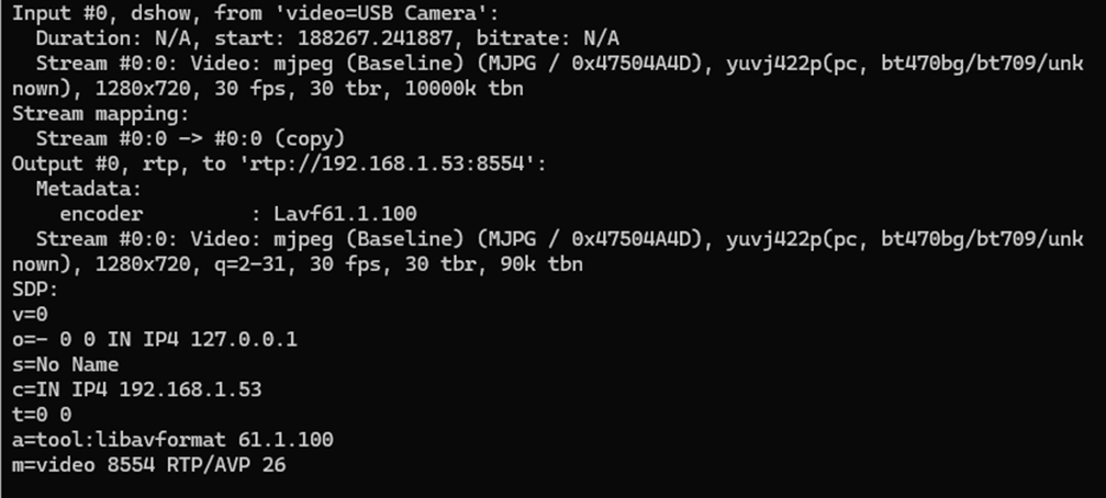
Here, we see the input, output, and SDP sections. In the input section, the codec is JPEG, which is what we need. The pixel format is yuvj422p, with a resolution of 1920x1080 at 30 fps. The stream parameters in the output section should match.
Next, save the SDP section to a file named stream.sdp on the HTTP server. Our EVS Driver application needs to fetch this file, which describes the stream.
In our example, the Android device should access this file at: http://192.168.1.59/stream.sdp
The exact content of the file should be:
v=0
o=- 0 0 IN IP4 127.0.0.1
s=No Name
c=IN IP4 192.168.1.53
t=0 0
a=tool:libavformat 61.1.100
m=video 8554 RTP/AVP 26
Now, restart the EVS Driver application on the Android device:
killall android.hardware.automotive.evs-default
Then, configure the EVS app to use the camera "rtp1". For detailed instructions on how to configure and launch the EVS (Exterior View System), refer to the article "Android AAOS 14 - Surround View Parking Camera: How to Configure and Launch EVS (Exterior View System)".
Performance Testing
In this chapter, we will measure and compare the latency of the video stream from a camera connected via USB and RTP.
How Did We Measure Latency?
- Setup Timer: Displayed a timer on the computer screen showing time with millisecond precision.
- Camera Capture: Pointed the EVS camera at this screen so that the timer was also visible on the Android device screen.
- Snapshot Comparison: Took photos of both screens simultaneously. The time displayed on the Android device was delayed compared to the computer screen. The difference in time between the computer and the Android device represents the camera's latency.
This latency is composed of several factors:
- Camera Latency: The time the camera takes to capture the image from the sensor and encode it into the appropriate format.
- Transmission Time: The time taken to transmit the data via USB or RTP.
- Decoding and Display: The time to decode the video stream and display the image on the screen.
Latency Comparison
Below are the photos showing the latency:
USB Camera
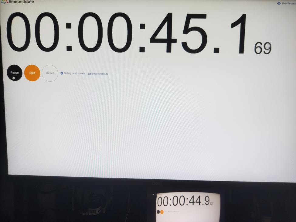
RTP Camera
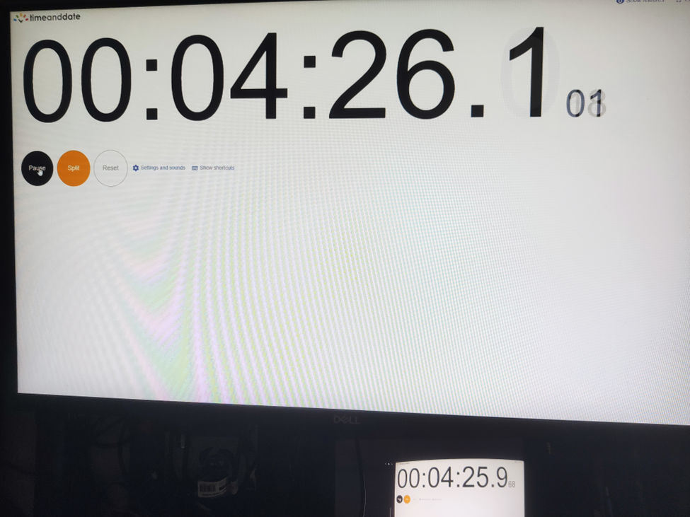
From these measurements, we found that the average latency for a camera connected via USB to the Android device is 200ms , while the latency for the camera connected via RTP is 150ms . This result is quite surprising.
The reasons behind these results are:
- The EVS implementation on Android captures video from the USB camera in YUV and similar formats, whereas FFmpeg streams RTP video in JPEG format.
- The USB camera used has a higher latency in generating YUV images compared to JPEG. Additionally, the frame rate is much lower. For a resolution of 1280x720, the YUV format only supports 10 fps, whereas JPEG supports the full 30 fps.
All camera modes can be checked using the command:
ffmpeg -f dshow -list_options true -i video="USB Camera"
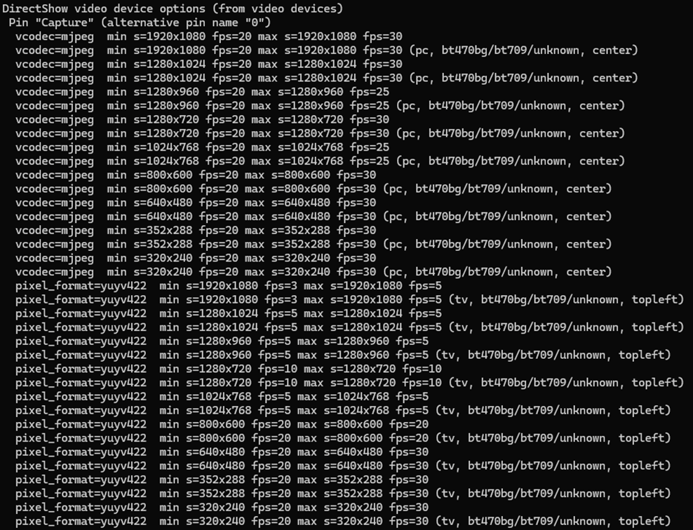
Conclusion
This article has taken you through the comprehensive process of integrating an RTP camera into the Android EVS (Exterior View System) framework, highlighting the detailed steps involved in both the implementation and the performance evaluation.
We began our journey by developing new classes, EvsRTPCamera and RTPCapture , which were specifically designed to handle RTP streams using FFmpeg. This adaptation allowed us to process and stream real-time video effectively. To ensure our system recognized the RTP camera, we made critical adjustments to the EvsEnumerator class. By customizing the enumerateCameras and openCamera functions, we ensured that our RTP camera was correctly instantiated and recognized by the system.
Next, we focused on building and deploying the EVS Driver application, including the necessary FFmpeg libraries, to our target Android device. This step was crucial for validating our implementation in a real-world environment. We also conducted a detailed performance evaluation to measure and compare the latency of video feeds from USB and RTP cameras. Using a timer displayed on a computer screen, we captured the timer with the EVS camera and compared the time shown on both the computer and Android screens. This method allowed us to accurately determine the latency introduced by each camera setup.
Our performance tests revealed that the RTP camera had an average latency of 150ms, while the USB camera had a latency of 200ms. This result was unexpected but highly informative. The lower latency of the RTP camera was largely due to the use of the JPEG format, which our particular USB camera handled less efficiently due to its slower YUV processing. This significant finding underscores the RTP camera's suitability for applications requiring real-time video performance, such as automotive surround view parking systems, where quick response times are essential for safety and user experience.

Modernizing legacy applications with generative AI: Lessons from R&D Projects
As digital transformation accelerates, modernizing legacy applications has become essential for businesses to stay competitive. The application modernization market size, valued at USD 21.32 billion in 2023 , is projected to reach USD 74.63 billion by 2031 (1), reflecting the growing importance of updating outdated systems.
With 94% of business executives viewing AI as key to future success and 76% increasing their investments in Generative AI due to its proven value (2), it's clear that AI is becoming a critical driver of innovation. One key area where AI is making a significant impact is application modernization - an essential step for businesses aiming to improve scalability, performance, and efficiency.
Based on two projects conducted by our R&D team , we've seen firsthand how Generative AI can streamline the process of rewriting legacy systems.
Let’s start by discussing the importance of rewriting legacy systems and how GenAI-driven solutions are transforming this process.
Why re-write applications?
In the rapidly evolving software development landscape, keeping applications up-to-date with the latest programming languages and technologies is crucial. Rewriting applications to new languages and frameworks can significantly enhance performance, security, and maintainability. However, this process is often labor-intensive and prone to human error.
Generative AI offers a transformative approach to code translation by:
- leveraging advanced machine learning models to automate the rewriting process
- ensuring consistency and efficiency
- accelerating modernization of legacy systems
- facilitating cross-platform development and code refactoring
As businesses strive to stay competitive, adopting Generative AI for code translation becomes increasingly important. It enables them to harness the full potential of modern technologies while minimizing risks associated with manual rewrites.
Legacy systems, often built on outdated technologies, pose significant challenges in terms of maintenance and scalability. Modernizing legacy applications with Generative AI provides a viable solution for rewriting these systems into modern programming languages, thereby extending their lifespan and improving their integration with contemporary software ecosystems.
This automated approach not only preserves core functionality but also enhances performance and security, making it easier for organizations to adapt to changing technological landscapes without the need for extensive manual intervention.
Why Generative AI?
Generative AI offers a powerful solution for rewriting applications, providing several key benefits that streamline the modernization process.
Modernizing legacy applications with Generative AI proves especially beneficial in this context for the following reasons:
- Identifying relationships and business rules: Generative AI can analyze legacy code to uncover complex dependencies and embedded business rules, ensuring critical functionalities are preserved and enhanced in the new system.
- Enhanced accuracy: Automating tasks like code analysis and documentation, Generative AI reduces human errors and ensures precise translation of legacy functionalities, resulting in a more reliable application.
- Reduced development time and cost: Automation significantly cuts down the time and resources needed for rewriting systems. Faster development cycles and fewer human hours required for coding and testing lower the overall project cost.
- Improved security: Generative AI aids in implementing advanced security measures in the new system, reducing the risk of threats and identifying vulnerabilities, which is crucial for modern applications.
- Performance optimization: Generative AI enables the creation of optimized code from the start, integrating advanced algorithms that improve efficiency and adaptability, often missing in older systems.
By leveraging Generative AI, organizations can achieve a smooth transition to modern system architectures, ensuring substantial returns in performance, scalability, and maintenance costs.
In this article, we will explore:
- the use of Generative AI for rewriting a simple CRUD application
- the use of Generative AI for rewriting a microservice-based application
- the challenges associated with using Generative AI
For these case studies, we used OpenAI's ChatGPT-4 with a context of 32k tokens to automate the rewriting process, demonstrating its advanced capabilities in understanding and generating code across different application architectures.
We'll also present the benefits of using a data analytics platform designed by Grape Up's experts. The platform utilizes Generative AI and neural graphs to enhance its data analysis capabilities, particularly in data integration, analytics, visualization, and insights automation.
Project 1: Simple CRUD application
The source CRUD project was used as an example of a simple CRUD application - one written utilizing .Net Core as a framework, Entity Framework Core for the ORM, and SQL Server for a relational database. The target project containes a backend application created using Java 17 and Spring Boot 3.
Steps taken to conclude the project
Rewriting a simple CRUD application using Generative AI involves a series of methodical steps to ensure a smooth transition from the old codebase to the new one. Below are the key actions undertaken during this process:
- initial architecture and data flow investigation - conducting a thorough analysis of the existing application's architecture and data flow.
- generating target application skeleton - creating the initial skeleton of the new application in the target language and framework.
- converting components - translating individual components from the original codebase to the new environment, ensuring that all CRUD operations were accurately replicated.
- generating tests - creating automated tests for the backend to ensure functionality and reliability.
Throughout each step, some manual intervention by developers was required to address code errors, compilation issues, and other problems encountered after using OpenAI's tools.
Initial architecture and data flows’ investigation
The first stage in rewriting a simple CRUD application using Generative AI is to conduct a thorough investigation of the existing architecture and data flow. This foundational step is crucial for understanding the current system's structure, dependencies, and business logic.
This involved:
- codebase analysis
- data flow mapping – from user inputs to database operations and back
- dependency identification
- business logic extraction – documenting the core business logic embedded within the application
While OpenAI's ChatGPT-4 is powerful, it has some limitations when dealing with large inputs or generating comprehensive explanations of entire projects. For example:
- OpenAI couldn’t read files directly from the file system
- Inputting several project files at once often resulted in unclear or overly general outputs
However, OpenAI excels at explaining large pieces of code or individual components. This capability aids in understanding the responsibilities of different components and their data flows. Despite this, developers had to conduct detailed investigations and analyses manually to ensure a complete and accurate understanding of the existing system.
This is the point at which we used our data analytics platform. In comparison to OpenAI, it focuses on data analysis. It's especially useful for analyzing data flows and project architecture, particularly thanks to its ability to process and visualize complex datasets. While it does not directly analyze source code, it can provide valuable insights into how data moves through a system and how different components interact.
Moreover, the platform excels at visualizing and analyzing data flows within your application. This can help identify inefficiencies, bottlenecks, and opportunities for optimization in the architecture.
Generating target application skeleton
As with OpenAI's inability to analyze the entire project, the attempt to generate the skeleton of the target application was also unsuccessful, so the developer had to manually create it. To facilitate this, Spring Initializr was used with the following configuration:
- Java: 17
- Spring Boot: 3.2.2
- Gradle: 8.5
Attempts to query OpenAI for the necessary Spring dependencies faced challenges due to significant differences between dependencies for C# and Java projects. Consequently, all required dependencies were added manually.
Additionally, the project included a database setup. While OpenAI provided a series of steps for adding database configuration to a Spring Boot application, these steps needed to be verified and implemented manually.
Converting components
After setting up the backend, the next step involved converting all project files - Controllers, Services, and Data Access layers - from C# to Java Spring Boot using OpenAI.
The AI proved effective in converting endpoints and data access layers, producing accurate translations with only minor errors, such as misspelled function names or calls to non-existent functions.
In cases where non-existent functions were generated, OpenAI was able to create the function bodies based on prompts describing their intended functionality. Additionally, OpenAI efficiently generated documentation for classes and functions.
However, it faced challenges when converting components with extensive framework-specific code. Due to differences between frameworks in various languages, the AI sometimes lost context and produced unusable code.
Overall, OpenAI excelled at:
- converting data access components
- generating REST APIs
However, it struggled with:
- service-layer components
- framework-specific code where direct mapping between programming languages was not possible
Despite these limitations, OpenAI significantly accelerated the conversion process, although manual intervention was required to address specific issues and ensure high-quality code.
Generating tests
Generating tests for the new code is a crucial step in ensuring the reliability and correctness of the rewritten application. This involves creating both unit tests and integration tests to validate individual components and their interactions within the system.
To create a new test, the entire component code was passed to OpenAI with the query: "Write Spring Boot test class for selected code."
OpenAI performed well at generating both integration tests and unit tests; however, there were some distinctions:
- For unit tests , OpenAI generated a new test for each if-clause in the method under test by default.
- For integration tests , only happy-path scenarios were generated with the given query.
- Error scenarios could also be generated by OpenAI, but these required more manual fixes due to a higher number of code issues.
If the test name is self-descriptive, OpenAI was able to generate unit tests with a lower number of errors.

Project 2: Microservice-based application
As an example of a microservice-based application, we used the Source microservice project - an application built using .Net Core as the framework, Entity Framework Core for the ORM, and a Command Query Responsibility Segregation (CQRS) approach for managing and querying entities. RabbitMQ was used to implement the CQRS approach and EventStore to store events and entity objects. Each microservice could be built using Docker, with docker-compose managing the dependencies between microservices and running them together.
The target project includes:
- a microservice-based backend application created with Java 17 and Spring Boot 3
- a frontend application using the React framework
- Docker support for each microservice
- docker-compose to run all microservices at once
Project stages
Similarly to the CRUD application rewriting project, converting a microservice-based application using Generative AI requires a series of steps to ensure a seamless transition from the old codebase to the new one. Below are the key steps undertaken during this process:
- initial architecture and data flows’ investigation - conducting a thorough analysis of the existing application's architecture and data flow.
- rewriting backend microservices - selecting an appropriate framework for implementing CQRS in Java, setting up a microservice skeleton, and translating the core business logic from the original language to Java Spring Boot.
- generating a new frontend application - developing a new frontend application using React to communicate with the backend microservices via REST APIs.
- generating tests for the frontend application - creating unit tests and integration tests to validate its functionality and interactions with the backend.
- containerizing new applications - generating Docker files for each microservice and a docker-compose file to manage the deployment and orchestration of the entire application stack.
Throughout each step, developers were required to intervene manually to address code errors, compilation issues, and other problems encountered after using OpenAI's tools. This approach ensured that the new application retains the functionality and reliability of the original system while leveraging modern technologies and best practices.
Initial architecture and data flows’ investigation
The first step in converting a microservice-based application using Generative AI is to conduct a thorough investigation of the existing architecture and data flows. This foundational step is crucial for understanding:
- the system’s structure
- its dependencies
- interactions between microservices
Challenges with OpenAI
Similar to the process for a simple CRUD application, at the time, OpenAI struggled with larger inputs and failed to generate a comprehensive explanation of the entire project. Attempts to describe the project or its data flows were unsuccessful because inputting several project files at once often resulted in unclear and overly general outputs.
OpenAI’s strengths
Despite these limitations, OpenAI proved effective in explaining large pieces of code or individual components. This capability helped in understanding:
- the responsibilities of different components
- their respective data flows
Developers can create a comprehensive blueprint for the new application by thoroughly investigating the initial architecture and data flows. This step ensures that all critical aspects of the existing system are understood and accounted for, paving the way for a successful transition to a modern microservice-based architecture using Generative AI.
Again, our data analytics platform was used in project architecture analysis. By identifying integration points between different application components, the platform helps ensure that the new application maintains necessary connections and data exchanges.
It can also provide a comprehensive view of your current architecture, highlighting interactions between different modules and services. This aids in planning the new architecture for efficiency and scalability. Furthermore, the platform's analytics capabilities support identifying potential risks in the rewriting process.
Rewriting backend microservices
Rewriting the backend of a microservice-based application involves several intricate steps, especially when working with specific architectural patterns like CQRS (Command Query Responsibility Segregation) and event sourcing . The source C# project uses the CQRS approach, implemented with frameworks such as NServiceBus and Aggregates , which facilitate message handling and event sourcing in the .NET ecosystem.
Challenges with OpenAI
Unfortunately, OpenAI struggled with converting framework-specific logic from C# to Java. When asked to convert components using NServiceBus, OpenAI responded:
"The provided C# code is using NServiceBus, a service bus for .NET, to handle messages. In Java Spring Boot, we don't have an exact equivalent of NServiceBus, but here's how you might convert the given C# code to Java Spring Boot..."
However, the generated code did not adequately cover the CQRS approach or event-sourcing mechanisms.
Choosing Axon framework
Due to these limitations, developers needed to investigate suitable Java frameworks. After thorough research, the Axon Framework was selected, as it offers comprehensive support for:
- domain-driven design
- CQRS
- event sourcing
Moreover, Axon provides out-of-the-box solutions for message brokering and event handling and has a Spring Boot integration library , making it a popular choice for building Java microservices based on CQRS.
Converting microservices
Each microservice from the source project could be converted to Java Spring Boot using a systematic approach, similar to converting a simple CRUD application. The process included:
- analyzing the data flow within each microservice to understand interactions and dependencies
- using Spring Initializr to create the initial skeleton for each microservice
- translating the core business logic, API endpoints, and data access layers from C# to Java
- creating unit and integration tests to validate each microservice’s functionality
- setting up the event sourcing mechanism and CQRS using the Axon Framework, including configuring Axon components and repositories for event sourcing
Manual Intervention
Due to the lack of direct mapping between the source project's CQRS framework and the Axon Framework, manual intervention was necessary. Developers had to implement framework-specific logic manually to ensure the new system retained the original's functionality and reliability.
Generating a new frontend application
The source project included a frontend component written using aspnetcore-https and aspnetcore-react libraries, allowing for the development of frontend components in both C# and React.
However, OpenAI struggled to convert this mixed codebase into a React-only application due to the extensive use of C#.
Consequently, it proved faster and more efficient to generate a new frontend application from scratch, leveraging the existing REST endpoints on the backend.
Similar to the process for a simple CRUD application, when prompted with “Generate React application which is calling a given endpoint” , OpenAI provided a series of steps to create a React application from a template and offered sample code for the frontend.
- OpenAI successfully generated React components for each endpoint
- The CSS files from the source project were reusable in the new frontend to maintain the same styling of the web application.
- However, the overall structure and architecture of the frontend application remained the developer's responsibility.
Despite its capabilities, OpenAI-generated components often exhibited issues such as:
- mixing up code from different React versions, leading to code failures.
- infinite rendering loops.
Additionally, there were challenges related to CORS policy and web security:
- OpenAI could not resolve CORS issues autonomously but provided explanations and possible steps for configuring CORS policies on both the backend and frontend
- It was unable to configure web security correctly.
- Moreover, since web security involves configurations on the frontend and multiple backend services, OpenAI could only suggest common patterns and approaches for handling these cases, which ultimately required manual intervention.
Generating tests for the frontend application
Once the frontend components were completed, the next task was to generate tests for these components. OpenAI proved to be quite effective in this area. When provided with the component code, OpenAI could generate simple unit tests using the Jest library.
OpenAI was also capable of generating integration tests for the frontend application, which are crucial for verifying that different components work together as expected and that the application interacts correctly with backend services.
However, some manual intervention was required to fix issues in the generated test code. The common problems encountered included:
- mixing up code from different React versions, leading to code failures.
- dependencies management conflicts, such as mixing up code from different test libraries.
Containerizing new application
The source application contained Dockerfiles that built images for C# applications. OpenAI successfully converted these Dockerfiles to a new approach using Java 17 , Spring Boot , and Gradle build tools by responding to the query:
"Could you convert selected code to run the same application but written in Java 17 Spring Boot with Gradle and Docker?"
Some manual updates, however, were needed to fix the actual jar name and file paths.
Once the React frontend application was implemented, OpenAI was able to generate a Dockerfile by responding to the query:
"How to dockerize a React application?"
Still, manual fixes were required to:
- replace paths to files and folders
- correct mistakes that emerged when generating multi-staged Dockerfiles , requiring further adjustments
While OpenAI was effective in converting individual Dockerfiles, it struggled with writing docker-compose files due to a lack of context regarding all services and their dependencies.
For instance, some microservices depend on database services, and OpenAI could not fully understand these relationships. As a result, the docker-compose file required significant manual intervention.
Conclusion
Modern tools like OpenAI's ChatGPT can significantly enhance software development productivity by automating various aspects of code writing and problem-solving. Leveraging large language models, such as OpenAI over ChatGPT can help generate large pieces of code, solve problems, and streamline certain tasks.
However, for complex projects based on microservices and specialized frameworks, developers still need to do considerable work manually, particularly in areas related to architecture, framework selection, and framework-specific code writing.
What Generative AI is good at:
- converting pieces of code from one language to another - Generative AI excels at translating individual code snippets between different programming languages, making it easier to migrate specific functionalities.
- generating large pieces of new code from scratch - OpenAI can generate substantial portions of new code, providing a solid foundation for further development.
- generating unit and integration tests - OpenAI is proficient in creating unit tests and integration tests, which are essential for validating the application's functionality and reliability.
- describing what code does - Generative AI can effectively explain the purpose and functionality of given code snippets, aiding in understanding and documentation.
- investigating code issues and proposing possible solutions - Generative AI can quickly analyze code issues and suggest potential fixes, speeding up the debugging process.
- containerizing application - OpenAI can create Dockerfiles for containerizing applications, facilitating consistent deployment environments.
At the time of project implementation, Generative AI still had several limitations .
- OpenAI struggled to provide comprehensive descriptions of an application's overall architecture and data flow, which are crucial for understanding complex systems.
- It also had difficulty identifying equivalent frameworks when migrating applications, requiring developers to conduct manual research.
- Setting up the foundational structure for microservices and configuring databases were tasks that still required significant developer intervention.
- Additionally, OpenAI struggled with managing dependencies, configuring web security (including CORS policies), and establishing a proper project structure, often needing manual adjustments to ensure functionality.
Benefits of using the data analytics platform:
- data flow visualization: It provides detailed visualizations of data movement within applications, helping to map out critical pathways and dependencies that need attention during re-writing.
- architectural insights : The platform offers a comprehensive analysis of system architecture, identifying interactions between components to aid in designing an efficient new structure.
- integration mapping: It highlights integration points with other systems or components, ensuring that necessary integrations are maintained in the re-written application.
- risk assessment: The platform's analytics capabilities help identify potential risks in the transition process, allowing for proactive management and mitigation.
By leveraging GenerativeAI’s strengths and addressing its limitations through manual intervention, developers can achieve a more efficient and accurate transition to modern programming languages and technologies. This hybrid approach to modernizing legacy applications with Generative AI currently ensures that the new application retains the functionality and reliability of the original system while benefiting from the advancements in modern software development practices.
It's worth remembering that Generative AI technologies are rapidly advancing, with improvements in processing capabilities. As Generative AI becomes more powerful, it is increasingly able to understand and manage complex project architectures and data flows. This evolution suggests that in the future, it will play a pivotal role in rewriting projects.
Do you need support in modernizing your legacy systems with expert-driven solutions?
.................
Sources:
- https://www.verifiedmarketresearch.com/product/application-modernization-market/
- https://www2.deloitte.com/content/dam/Deloitte/us/Documents/deloitte-analytics/us-ai-institute-state-of-ai-fifth-edition.pdf

Building EU-compliant connected car software under the EU Data Act
The EU Data Act is about to change the rules of the game for many industries, and automotive OEMs are no exception. With new regulations aimed at making data generated by connected vehicles more accessible to consumers and third parties, OEMs are experiencing a major shift. So, what does this mean for the automotive space?
First, it means rethinking how data is managed, shared, and protected . OEMs must now meet new requirements for data portability, security, and privacy, using software compliant with the EU Data Act.
This guide will walk you through how they can prepare to not just survive but thrive under the new regulations.
The EU Data Act deadlines OEMs can’t miss
- Chapter II (B2B and B2C data sharing) has a deadline of September 2025.
- Article 3 (accessibility by design) has a deadline of September 2026.
- Chapter IV (contractual terms between businesses) has a deadline of September 2027.
Compliance requirements for automotive OEMs
The EU Data Act establishes specific obligations for automotive OEMs to ensure secure, transparent, and fair data sharing with both consumers (B2C) and third-party businesses (B2B). The following key provisions outline the requirements that OEMs must fulfill to comply with the Act.
B2C obligations
- Data accessibility for users:
- Connected products, such as vehicles, must be built in a way that makes data generated by their use accessible in a structured, machine-readable format. This requirement applies from the manufacturing stage, meaning the design process must incorporate data accessibility features.
- User control over data:
- Users should have the ability to control how their data is used, including the right to share it with third parties of their choice. This requires OEMs to implement systems that allow consumers to grant and revoke access to their data seamlessly.
- Transparency in data practices:
- OEMs are required to provide clear and transparent information about the nature and volume of collected data and the way to access it.
- When a user requests to make data available to a third party, the OEM must inform them about:
a) The identity of the third party
b) The purpose of data use
c) The type of data that will be shared
d) The right of the user to withdraw consent for the third party to access the data
B2B obligations
1. Fair access to data:
- OEMs must ensure that data generated by connected products is accessible to third parties at the user’s request under fair, reasonable, and non-discriminatory conditions.
- This means that data sharing cannot be restricted to certain partners or proprietary platforms; it must be available to a broad range of businesses, including independent repair shops, insurers, and fleet managers.
2. Compliance with security and privacy regulations:
- While sharing non-personal data, OEMs must still comply with relevant data security and privacy regulations. This means that data must be protected from unauthorized access and that any data-sharing agreements are in line with the EU Data Act and GDPR.
3. Protection of trade secrets
- OEMs have a right and obligation to protect their trade secrets and should only disclose them when necessary to meet the agreed purpose. This means identifying protected data, agreeing on confidentiality measures with third parties, and suspending data sharing if these measures are not properly followed or if sharing would cause significant economic harm.
Understanding the specific obligations is only the first step for automotive OEMs. Based on this information, they can build software compliant with the EU Data Act. To navigate these new requirements effectively, OEMs need to adopt an approach that not only meets regulatory demands but also strengthens their competitive edge.
Thriving under the EU Data Act: smart investments and privacy-first strategies
Automotive OEMs must take a strategic approach to both their software and operational frameworks, balancing compliance requirements with innovation and customer trust. The key is to prioritize solutions that improve data accessibility and governance while minimizing costs. This starts with redesigning connected products and services to align with the Act’s data-sharing mandates and creating solutions to handle data requests efficiently.
Another critical focus is balancing privacy concerns with data-sharing obligations . OEMs must handle non-personal data responsibly under the EU Data Act while managing personal data in accordance with GDPR. This includes providing transparency about data usage and giving customers control over their data.
To achieve this balance, OEMs should identify which data needs to be shared with third parties and integrate privacy considerations across all stages of product development and data management. Transparent communication about data use, supported by clear policies and customer controls, helps to reinforce this trust.
Opportunities under the EU Data Act
The EU Data Act presents compliance challenges, but it also offers significant opportunities for OEMs that are prepared to adapt. By meeting the Act’s requirements for fair data sharing, OEMs can expand their services and build new partnerships. While direct monetization from data access fees is limited, there are numerous opportunities to leverage shared data to develop new value-added services and improve operational efficiency.
Next steps for automotive OEMs
To move to implementation, OEMs must take targeted actions that address the compliance requirements outlined earlier. These steps lay the groundwork for integrating broader strategies and turning compliance efforts into opportunities for operational improvement and future growth.
Integrate data accessibility into vehicle design
Start integrating data accessibility into vehicle design now to comply by 2026. This involves adapting both front and back-end components of products and services to enable secure and seamless data access and transfer according to the EU Data Act.
Provide user and third-party access to generated data
Introduce easy-to-use mechanisms that let users request access to their data or share it with chosen third parties. Access control should be straightforward, involving simple user identification and making data accessible to authorized users upon request. Develop dedicated data-sharing solutions, applications, or portals that enable third parties to request access to data with user consent.
Implement trade secret protection measures
OEMs should protect their trade secrets by identifying which vehicle data is commercially sensitive. Implement measures like data encryption and access controls to safeguard this information when sharing data. Clearly communicate your approach to protecting trade secrets without disclosing the sensitive information itself.
Implement transparent and secure data handling
Provide clear information to users about what data is collected, how it is used, and with whom it is shared. Transparent data practices help build trust and align with users' data rights under the EU Data Act.
Remember about the non-personal data that is being collected, too. Apply appropriate measures to preserve data quality and prevent its unauthorized access, transfer, or use.
Enable data interoperability and portability
The Act sets out essential requirements to facilitate the interoperability of data and data-sharing mechanisms, with a strong emphasis on data portability. OEMs need to make their data systems compatible with third-party services, allowing data to be easily transferred between platforms.
For example, if a car owner wants to switch from an OEM-provided app to a third-party app for vehicle diagnostics, OEMs must not create technical, contractual, or organizational barriers that would make this switch difficult.
Prepare the data
Choose a data format that fulfills the EU Data Act’s requirement for data to be shared in a “commonly used and machine-readable format.” This approach supports data accessibility and usability across different platforms and services.
Moving forward with confidence
The EU Data Act is bringing new obligations but also offering valuable opportunities. Navigating these changes may seem challenging, but with the right approach, they can become a catalyst for growth.
AAOS 14 - Surround view parking camera: How to configure and launch exterior view system

EVS - park mode
The Android Automotive Operating System (AAOS) 14 introduces significant advancements, including a Surround View Parking Camera system. This feature, part of the Exterior View System (EVS), provides a comprehensive 360-degree view around the vehicle, enhancing parking safety and ease. This article will guide you through the process of configuring and launching the EVS on AAOS 14 .
Structure of the EVS system in Android 14
The Exterior View System (EVS) in Android 14 is a sophisticated integration designed to enhance driver awareness and safety through multiple external camera feeds. This system is composed of three primary components: the EVS Driver application, the Manager application, and the EVS App. Each component plays a crucial role in capturing, managing, and displaying the images necessary for a comprehensive view of the vehicle's surroundings.
EVS driver application
The EVS Driver application serves as the cornerstone of the EVS system, responsible for capturing images from the vehicle's cameras. These images are delivered as RGBA image buffers, which are essential for further processing and display. Typically, the Driver application is provided by the vehicle manufacturer, tailored to ensure compatibility with the specific hardware and camera setup of the vehicle.
To aid developers, Android 14 includes a sample implementation of the Driver application that utilizes the Linux V4L2 (Video for Linux 2) subsystem. This example demonstrates how to capture images from USB-connected cameras, offering a practical reference for creating compatible Driver applications. The sample implementation is located in the Android source code at packages/services/Car/cpp/evs/sampleDriver .
Manager application
The Manager application acts as the intermediary between the Driver application and the EVS App. Its primary responsibilities include managing the connected cameras and displays within the system.
Key Tasks :
- Camera Management : Controls and coordinates the various cameras connected to the vehicle.
- Display Management : Manages the display units, ensuring the correct images are shown based on the input from the Driver application.
- Communication : Facilitates communication between the Driver application and the EVS App, ensuring a smooth data flow and integration.
EVS app
The EVS App is the central component of the EVS system, responsible for assembling the images from the various cameras and displaying them on the vehicle's screen. This application adapts the displayed content based on the vehicle's gear selection, providing relevant visual information to the driver.
For instance, when the vehicle is in reverse gear (VehicleGear::GEAR_REVERSE), the EVS App displays the rear camera feed to assist with reversing maneuvers. When the vehicle is in park gear (VehicleGear::GEAR_PARK), the app showcases a 360-degree view by stitching images from four cameras, offering a comprehensive overview of the vehicle’s surroundings. In other gear positions, the EVS App stops displaying images and remains in the background, ready to activate when the gear changes again.
The EVS App achieves this dynamic functionality by subscribing to signals from the Vehicle Hardware Abstraction Layer (VHAL), specifically the VehicleProperty::GEAR_SELECTION . This allows the app to adjust the displayed content in real-time based on the current gear of the vehicle.
Communication interface
Communication between the Driver application, Manager application, and EVS App is facilitated through the IEvsEnumerator HAL interface. This interface plays a crucial role in the EVS system, ensuring that image data is captured, managed, and displayed accurately. The IEvsEnumerator interface is defined in the Android source code at hardware/interfaces/automotive/evs/1.0/IEvsEnumerator.hal .
EVS subsystem update
Evs source code is located in: packages/services/Car/cpp/evs. Please make sure you use the latest sources because there were some bugs in the later version that cause Evs to not work.
cd  packages/services/Car/cpp/evs
git checkout main
git pull
mm
adb push out/target/product/rpi4/vendor/bin/hw/android.hardware.automotive.evs-default /vendor/bin/hw/
adb push out/target/product/rpi4/system/bin/evs_app /system/bin/
EVS driver configuration
To begin, we need to configure the EVS Driver. The configuration file is located at /vendor/etc/automotive/evs/evs_configuration_override.xml .
Here is an example of its content:
<configuration>
    <!-- system configuration -->
    <system>
        <!-- number of cameras available to EVS -->
        <num_cameras value='2'/>
    </system>

    <!-- camera device information -->
    <camera>

        <!-- camera device starts -->
        <device id='/dev/video0' position='rear'>
            <caps>
                <!-- list of supported controls -->
                <supported_controls>
                    <control name='BRIGHTNESS' min='0' max='255'/>
                    <control name='CONTRAST' min='0' max='255'/>
                    <control name='AUTO_WHITE_BALANCE' min='0' max='1'/>
                    <control name='WHITE_BALANCE_TEMPERATURE' min='2000' max='7500'/>
                    <control name='SHARPNESS' min='0' max='255'/>
                    <control name='AUTO_FOCUS' min='0' max='1'/>
                    <control name='ABSOLUTE_FOCUS' min='0' max='255' step='5'/>
                    <control name='ABSOLUTE_ZOOM' min='100' max='400'/>
                </supported_controls>

                <!-- list of supported stream configurations -->
                <!-- below configurations were taken from v4l2-ctrl query on
                     Logitech Webcam C930e device -->
                <stream id='0' width='1280' height='720' format='RGBA_8888' framerate='30'/>
            </caps>

            <!-- list of parameters -->
            <characteristics>

            </characteristics>
        </device>
        <device id='/dev/video2' position='front'>
            <caps>
                <!-- list of supported controls -->
                <supported_controls>
                    <control name='BRIGHTNESS' min='0' max='255'/>
                    <control name='CONTRAST' min='0' max='255'/>
                    <control name='AUTO_WHITE_BALANCE' min='0' max='1'/>
                    <control name='WHITE_BALANCE_TEMPERATURE' min='2000' max='7500'/>
                    <control name='SHARPNESS' min='0' max='255'/>
                    <control name='AUTO_FOCUS' min='0' max='1'/>
                    <control name='ABSOLUTE_FOCUS' min='0' max='255' step='5'/>
                    <control name='ABSOLUTE_ZOOM' min='100' max='400'/>
                </supported_controls>

                <!-- list of supported stream configurations -->
                <!-- below configurations were taken from v4l2-ctrl query on
                     Logitech Webcam C930e device -->
                <stream id='0' width='1280' height='720' format='RGBA_8888' framerate='30'/>
            </caps>

            <!-- list of parameters -->
            <characteristics>

            </characteristics>
        </device>
    </camera>

    <!-- display device starts -->
    <display>
        <device id='display0' position='driver'>
            <caps>
                <!-- list of supported inpu stream configurations -->
                <stream id='0' width='1280' height='800' format='RGBA_8888' framerate='30'/>
            </caps>
        </device>
    </display>
</configuration>
In this configuration, two cameras are defined: /dev/video0 (rear) and /dev/video2 (front). Both cameras have one stream defined with a resolution of 1280 x 720, a frame rate of 30, and an RGBA format.
Additionally, there is one display defined with a resolution of 1280 x 800, a frame rate of 30, and an RGBA format.
Configuration details
The configuration file starts by specifying the number of cameras available to the EVS system. This is done within the <system> tag, where the <num_cameras> tag sets the number of cameras to 2.
Each camera device is defined within the <camera> tag. For example, the rear camera ( /dev/video0 ) is defined with various capabilities such as brightness, contrast, auto white balance, and more. These capabilities are listed under the <supported_controls> tag. Similarly, the front camera ( /dev/video2 ) is defined with the same set of controls.
Both cameras also have their supported stream configurations listed under the <stream> tag. These configurations specify the resolution, format, and frame rate of the video streams.
The display device is defined under the <display> tag. The display configuration includes supported input stream configurations, specifying the resolution, format, and frame rate.
EVS driver operation
When the EVS Driver starts, it reads this configuration file to understand the available cameras and display settings. It then sends this configuration information to the Manager application. The EVS Driver will wait for requests to open and read from the cameras, operating according to the defined configurations.
EVS app configuration
Configuring the EVS App is more complex. We need to determine how the images from individual cameras will be combined to create a 360-degree view. In the repository, the file packages/services/Car/cpp/evs/apps/default/res/config.json.readme contains a description of the configuration sections:
{
  "car" : {                     // This section describes the geometry of the car
    "width"  : 76.7,            // The width of the car body
    "wheelBase" : 117.9,        // The distance between the front and rear axles
    "frontExtent" : 44.7,       // The extent of the car body ahead of the front axle
    "rearExtent" : 40           // The extent of the car body behind the rear axle
  },
  "displays" : [                // This configures the dimensions of the surround view display
    {                           // The first display will be used as the default display
      "displayPort" : 1,        // Display port number, the target display is connected to
      "frontRange" : 100,       // How far to render the view in front of the front bumper
      "rearRange" : 100         // How far the view extends behind the rear bumper
    }
  ],
  "graphic" : {                 // This maps the car texture into the projected view space
    "frontPixel" : 23,          // The pixel row in CarFromTop.png at which the front bumper appears
    "rearPixel" : 223           // The pixel row in CarFromTop.png at which the back bumper ends
  },
  "cameras" : [                 // This describes the cameras potentially available on the car
    {
      "cameraId" : "/dev/video32",  // Camera ID exposed by EVS HAL
      "function" : "reverse,park",  // Set of modes to which this camera contributes
      "x" : 0.0,                    // Optical center distance right of vehicle center
      "y" : -40.0,                  // Optical center distance forward of rear axle
      "z" : 48,                     // Optical center distance above ground
      "yaw" : 180,                  // Optical axis degrees to the left of straight ahead
      "pitch" : -30,                // Optical axis degrees above the horizon
      "roll" : 0,                   // Rotation degrees around the optical axis
      "hfov" : 125,                 // Horizontal field of view in degrees
      "vfov" : 103,                 // Vertical field of view in degrees
      "hflip" : true,               // Flip the view horizontally
      "vflip" : true                // Flip the view vertically
    }
  ]
}
The EVS app configuration file is crucial for setting up the system for a specific car. Although the inclusion of comments makes this example an invalid JSON, it serves to illustrate the expected format of the configuration file. Additionally, the system requires an image named CarFromTop.png to represent the car.
In the configuration, units of length are arbitrary but must remain consistent throughout the file. In this example, units of length are in inches.
The coordinate system is right-handed: X represents the right direction, Y is forward, and Z is up, with the origin located at the center of the rear axle at ground level. Angle units are in degrees, with yaw measured from the front of the car, positive to the left (positive Z rotation). Pitch is measured from the horizon, positive upwards (positive X rotation), and roll is always assumed to be zero. Please keep in mind that, unit of angles are in degrees, but they are converted to radians during configuration reading. So, if you want to change it in EVS App source code, use radians.
This setup allows the EVS app to accurately interpret and render the camera images for the surround view parking system.
The configuration file for the EVS App is located at /vendor/etc/automotive/evs/config_override.json . Below is an example configuration with two cameras, front and rear, corresponding to our driver setup:
{
  "car": {
    "width": 76.7,
    "wheelBase": 117.9,
    "frontExtent": 44.7,
    "rearExtent": 40
  },
  "displays": [
    {
      "_comment": "Display0",
      "displayPort": 0,
      "frontRange": 100,
      "rearRange": 100
    }
  ],
  "graphic": {
    "frontPixel": -20,
    "rearPixel": 260
  },
  "cameras": [
    {
      "cameraId": "/dev/video0",
      "function": "reverse,park",
      "x": 0.0,
      "y": 20.0,
      "z": 48,
      "yaw": 180,
      "pitch": -10,
      "roll": 0,
      "hfov": 115,
      "vfov": 80,
      "hflip": false,
      "vflip": false
    },
    {
      "cameraId": "/dev/video2",
      "function": "front,park",
      "x": 0.0,
      "y": 100.0,
      "z": 48,
      "yaw": 0,
      "pitch": -10,
      "roll": 0,
      "hfov": 115,
      "vfov": 80,
      "hflip": false,
      "vflip": false
    }
  ]
}
Running EVS
Make sure all apps are running:
ps -A | grep evs
automotive_evs 3722    1   11007600   6716 binder_thread_read  0 S evsmanagerd
graphics      3723     1   11362488  30868 binder_thread_read  0 S android.hardware.automotive.evs-default
automotive_evs 3736    1   11068388   9116 futex_wait          0 S evs_app
To simulate reverse gear you can call:
evs_app --test --gear reverse

And park:
evs_app --test --gear park

EVS app should be displayed on the screen.
Troubleshooting
When configuring and launching the EVS (Exterior View System) for the Surround View Parking Camera in Android AAOS 14, you may encounter several issues.
To debug that, you can use logs from EVS system:
logcat EvsDriver:D EvsApp:D evsmanagerd:D *:S
Multiple USB cameras - image freeze
During the initialization of the EVS system, we encountered an issue with the image feed from two USB cameras. While the feed from one camera displayed smoothly, the feed from the second camera either did not appear at all or froze after displaying a few frames.
We discovered that the problem lay in the USB communication between the camera and the V4L2 uvcvideo driver. During the connection negotiation, the camera reserved all available USB bandwidth. To prevent this, the uvcvideo driver needs to be configured with the parameter quirks=128 . This setting allows the driver to allocate the USB bandwidth based on the actual resolution and frame rate of the camera.
To implement this solution, the parameter should be set in the bootloader, within the kernel command line, for example:
console=ttyS0,115200 no_console_suspend root=/dev/ram0 rootwait androidboot.hardware=rpi4 androidboot.selinux=permissive uvcvideo.quirks=128
After applying this setting, the image feed from both cameras should display smoothly, resolving the freezing issue.
Green frame around camera image
In the current implementation of the EVS system, the camera image is surrounded by a green frame, as illustrated in the following image:

To eliminate this green frame, you need to modify the implementation of the EVS Driver. Specifically, you should edit the GlWrapper.cpp file located at cpp/evs/sampleDriver/aidl/src/ .
In the void GlWrapper::renderImageToScreen() function, change the following lines:
-0.8, 0.8, 0.0f, // left top in window space
 0.8, 0.8, 0.0f, // right top
-0.8, -0.8, 0.0f, // left bottom
 0.8, -0.8, 0.0f // right bottom
to
-1.0,  1.0, 0.0f,  // left top in window space
 1.0,  1.0, 0.0f,  // right top
-1.0, -1.0, 0.0f,  // left bottom
 1.0, -1.0, 0.0f   // right bottom
After making this change, rebuild the EVS Driver and deploy it to your device. The camera image should now be displayed full screen without the green frame.
Conclusion
In this article, we delved into the intricacies of configuring and launching the EVS (Exterior View System) for the Surround View Parking Camera in Android AAOS 14. We explored the critical components that make up the EVS system: the EVS Driver, EVS Manager, and EVS App, detailing their roles and interactions.
The EVS Driver is responsible for providing image buffers from the vehicle's cameras, leveraging a sample implementation using the Linux V4L2 subsystem to handle USB-connected cameras. The EVS Manager acts as an intermediary, managing camera and display resources and facilitating communication between the EVS Driver and the EVS App. Finally, the EVS App compiles the images from various cameras, displaying a cohesive 360-degree view around the vehicle based on the gear selection and other signals from the Vehicle HAL.
Configuring the EVS system involves setting up the EVS Driver through a comprehensive XML configuration file, defining camera and display parameters. Additionally, the EVS App configuration, outlined in a JSON file, ensures the correct mapping and stitching of camera images to provide an accurate surround view.
By understanding and implementing these configurations, developers can harness the full potential of the Android AAOS 14 platform to enhance vehicle safety and driver assistance through an effective Surround View Parking Camera system. This comprehensive setup not only improves the parking experience but also sets a foundation for future advancements in automotive technology.
How to make your enterprise data ready for AI
As AI continues to transform industries, one thing becomes increasingly clear: the success of AI-driven initiatives depends not just on algorithms but on the quality and readiness of the data that fuels them. Without well-prepared data, even the most advanced artificial intelligence endeavors can fall short of their promise. In this guide, we cover the practical steps you need to take to prepare your data for AI.
What's the point of AI-ready data?
The conversation around AI has shifted dramatically in recent years. No longer a distant possibility, AI is now actively changing business landscapes - transforming supply chains through predictive analytics, personalizing customer experiences with advanced recommendation engines, and even assisting in complex fields like financial modeling and healthcare diagnostics.
The focus today is not on whether AI technologies can fulfill its potential but on how organizations can best deploy it to achieve meaningful, scalable business outcomes.
Despite pouring significant resources into AI, businesses are still finding it challenging to fully tap into its economic potential.
For example, according to Gartner , 50% of organizations are actively assessing GenAI's potential, and 33% are in the piloting stage. Meanwhile, only 9% have fully implemented generative AI applications in production, while 8% do not consider them at all.
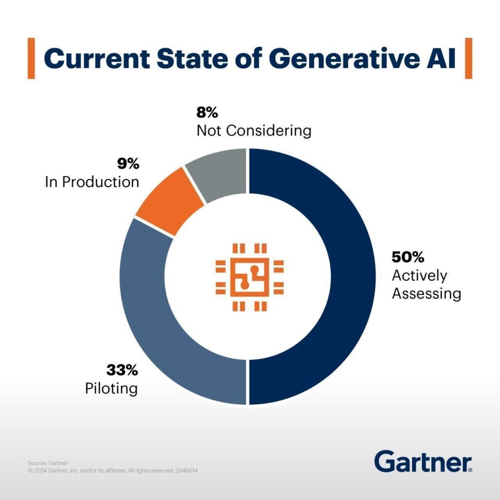
Source: www.gartner.com
The problem often comes down to a key but frequently overlooked factor: the relationship between AI and data. The key issue is the lack of data preparedness . In fact, only 37% of data leaders believe that their organizations have the right data foundation for generative AI, with just 11% agreeing strongly. That means specifically that chief data officers and data leaders need to develop new data strategies and improve data quality to make generative AI work effectively .
What does your business gain by getting your data AI-ready?
When your data is clean, organized, and well-managed , AI can help you make smarter decisions, boost efficiency, and even give you a leg up on the competition .
So, what exactly are the benefits of putting in the effort to prepare your data for AI? Let’s break it down into some real, tangible advantages.
- Clean, organized data allows AI to quickly analyze large amounts of information, helping businesses understand customer preferences, spot market trends, and respond more effectively to changes.
- Getting data AI-ready can save time by automating repetitive tasks and reducing errors.
- When data is properly prepared, AI can offer personalized recommendations and targeted marketing, which can enhance customer satisfaction and build loyalty.
- Companies that prepare their data for AI can move faster, innovate more easily, and adapt better to changes in the market, giving them a clear edge over competitors.
- Proper data preparation ensures businesses can comply with regulations and protect sensitive information.
Importance of data readiness for AI
Unlike traditional algorithms that were bound by predefined rules, modern AI systems learn and adapt dynamically when they have access to data that is both diverse and high-quality.
For many businesses, the challenge is that their data is often trapped in outdated legacy systems that are not built to handle the volume, variety, or velocity required for effective AI. To enable AI to innovate, companies need to first free their data from old silos and establish a proper data infrastructure.
Key considerations for data modernization
- Bring together data from different sources to create a complete picture, which is essential for AI systems to make useful interpretations.
- Build a flexible data infrastructure that can handle increasing amounts of data and adapt to changing AI needs.
- Set up systems to process data in real-time or near-real-time for applications that need immediate insights.
- Consider ethical and privacy issues and comply with regulations like GDPR or CCPA.
- Continuously monitor data quality and AI performance to maintain accuracy and usefulness.
- Employ data augmentation techniques to increase the variety and volume of data for training AI models when needed.
- Create feedback mechanisms to improve data quality and AI performance based on real-world results.
Creating data strategy for AI
Many organizations fall into the trap of trying to apply AI across every function, often ending up with wasted resources and disappointing results. A smarter approach is to start with a focused data strategy.
Think about where AI can truly make a difference – would it be automating repetitive scheduling tasks, personalizing customer experiences with predictive analytics , or using generative AI for content creation and market analysis?
Pinpoint high-impact areas to gain business value without spreading your efforts too thin.
Building a solid AI strategy is also about creating a strong data foundation that brings all factors together. This means making sure your data is not only reliable, secure, and well-organized but also set up to support specific AI use cases effectively.
It also involves creating an environment that encourages experimentation and learning. This way, your organization can continuously adapt, refine its approach, and get the most out of AI over time.
Building an AI-optimized data infrastructure
After establishing an AI strategy, the next step is building a data platform that works like the organization’s central nervous system, connecting all data sources into a unified, dynamic ecosystem.
Why do you need it? Because traditional data architectures were built for simpler times and can't handle the sheer diversity and volume of today's data - everything from structured databases to unstructured content like videos, audio, and user-generated data.
An AI-ready data platform needs to accommodate all these different data types while ensuring quick and efficient access so that AI models can work with the most relevant, up-to-date information.
Your data platform needs to show "data lineage" - essentially, a clear map of how data moves through your system. This includes where the data originates, how it’s transformed over time, and how it gets used in the end. Understanding this flow maintains trust in the data, which AI models rely on to make accurate decisions.
At the same time, the platform should support "data liquidity." This is about breaking data into smaller, manageable pieces that can easily flow between different systems and formats. AI models need this kind of flexibility to get access to the right information when they need it.
Adding active metadata management to this mix provides context, making data easier to interpret and use. When all these components are in place, they turn raw data into a valuable, AI-ready asset.
Setting up data governance and management rules
Think of data governance as defining the rules of the game: how data should be collected, stored, and accessed across your organization. This includes setting up clear policies on data ownership, access controls, and regulatory compliance to protect sensitive information and ensure your data is ethical, unbiased, and trustworthy.
Data management , on the other hand, is all about putting these rules into action. It involves integrating data from different sources, cleaning it up, and storing it securely , all while making sure that high-quality data is always available for your AI projects. Effective data management also means balancing security with access so your team can quickly get to the data they need without compromising privacy or compliance. Together, strong governance and management practices create a fluid, efficient data environment.
The crux of the matter - preparing your data
Remember that data readiness goes beyond just accumulating volume. The key is to make sure that data remains accurate and aligned with the specific AI objectives. Raw data, coming straight from its source, is often filled with errors, inconsistencies, and irrelevant information that can mislead AI models or distort results.
When you handle data with care, you can be confident that your AI systems will deliver tangible business value across the organization.
Focus on the quality of your training data . It needs to be accurate, consistent, and up-to-date. If there are gaps or errors, your AI models will deliver unreliable results. Address these issues by using data cleaning techniques , like filling in missing values (imputation), removing irrelevant information (noise reduction), and ensuring that all entries follow the same format.
Create a solid data foundation that ensures all assets are ready for AI applications. Rising data volumes (think of transaction histories, service requests, or customer records) can quickly overwhelm AI systems if not properly organized. Therefore, make sure your data is well- categorized, labeled, and stored in a format that’s easy for AI to access and analyze.
Also, make a habit of regularly reviewing your data to keep it accurate, relevant, and ready for use.
Preparing data for generative AI
For generative AI, data preparation is even more specialized, as these models require high-quality datasets that are free of errors, diverse and balanced to prevent biased or misleading outputs.
Your dataset should represent a wide range of scenarios , giving the model a thorough base to learn from, which requires incorporating data from multiple sources, demographics, and contexts.
Also, consider that generative AI models often require specific preprocessing steps depending on the type of data and the model architecture. For example, text data might need tokenization, while image data might require normalization or augmentation.
The big picture - get your organization AI-ready too
All your efforts with data and AI tools won't matter much if your organization isn’t prepared to embrace these changes. The key is building a team that combines tech talent - like data scientists and machine learning experts - with people who understand your business deeply. This means you might need to train and upskill your existing employees to fill gaps.
But there is more – you also need to think about creating a culture that welcomes transformation . Encourage experimentation, cross-team collaboration, and continuous learning. Make sure everyone understands both the potential and the risks of AI. When your team feels confident and aligned with your AI strategy, that’s when you’ll see the real impact of all your hard work.
By focusing on these steps, you create a solid foundation that helps AI deliver real results, whether that's through better decision-making, improving customer experiences, or staying competitive in a fast-changing market. Preparing your data may take some effort upfront, but it will make a big difference in how well your AI projects perform in the long run.
Challenges of the legacy migration process and best practices to mitigate them
Legacy software is the backbone of many organizations, but as technology advances, these systems can become more of a burden than a benefit. Migrating from a legacy system to a modern solution is a daunting task fraught with challenges, from grappling with outdated code and conflicting stakeholder interests to managing dependencies on third-party vendors and ensuring compliance with stringent regulatory standards.
However, with the right strategies and leveraging advanced technologies like Generative AI, these challenges can be effectively mitigated.
Challenge #1: Limited knowledge of the legacy solution
The average lifespan of business software can vary widely depending on several factors, such as the type of software or the industry it serves. Nevertheless, no matter if the software is 5 or 25 years old, it is highly possible its creators and subject matter experts are not accessible anymore (or they barely remember what they built and how it really works), the documentation is incomplete, the code messy and the technology forgotten a long time ago.
Lack of knowledge of the legacy solution not only blocks its further development and maintenance but also negatively affects its migration – it significantly slows down the analysis and replacement process.
Mitigation:
The only way to understand what kind of functionality, processes and dependencies are covered by the legacy software and what really needs to get migrated is in-depth analysis. An extensive discovery phase initiating every migration project should cover:
- interviews with the key users and knowledge keepers,
- observations of the employees and daily operations performed within the system,
- study of all the available documentation and resources,
- source code examination.
The discovery phase, although long (and boring!), demanding, and very costly, is crucial for the migration project’s success. Therefore, it is not recommended to give in to the temptation to take any shortcuts there.
At Grape Up , we do not. We make sure we learn the legacy software in detail, optimizing the analytical efforts at the same time. We support the discovery process by leveraging Generative AI tools . They help us to understand the legacy spaghetti code, forgotten purpose, dependencies, and limitations. GenAI enables us to make use of existing incomplete documentation or to go through technologies that nobody has expertise in anymore. This approach significantly speeds the discovery phase up, making it smoother and more efficient.
Challenge #2: Blurry idea of the target solution & conflicting interests
Unfortunately, understanding the legacy software and having a complete idea of the target replacement are two separate things. A decision to build a new solution, especially in a corporate environment, usually encourages multiple stakeholders (representing different groups of interests) to promote their visions and ideas. Often conflicting, to be precise.
This nonlinear stream of contradicting requirements leads to an uncontrollable growth of the product backlog, which becomes extremely difficult to manage and prioritize. In consequence, efficient decision-making (essential for the product’s success) is barely possible.
Mitigation:
A strong Product Management community with a single product leader - empowered to make decisions and respected by the entire organization – is the key factor here. If combined with a matching delivery model (which may vary depending on a product & project specifics), it sets the goals and frames for the mission and guides its crew.
For huge legacy migration projects with a blurry scope, requiring constant validation and prioritization, an Agile-based, continuous discovery & delivery process is the only possible way to go. With a flexible product roadmap (adjusted on the fly), both creative and development teams work simultaneously, and regular feedback loops are established.
High pressure from the stakeholders always makes the Product Leader’s job difficult. Bold scope decisions become easier when MVP/MDP (Minimum Viable / Desirable Product) approach & MoSCoW (must-have, should-have, could-have, and won't-have, or will not have right now) prioritization technique are in place.
At Grape Up, we assist our clients with establishing and maintaining efficient product & project governance, supporting the in-house management team with our experienced consultants such as Business Analysts, Scrum Masters, Project Managers, or Proxy Product Owners.
Challenge #3: Strategical decisions impacting the future
Migrating the legacy software gives the organization a unique opportunity to sunset outdated technologies, remove all the infrastructural pain points, reach out for modern solutions, and sketch a completely new architecture.
However, these are very heavy decisions. They must not only address the current needs but also be adaptable to future growth. Wrong choices can result in technical debt, forcing another costly migration – much sooner than planned.
Mitigation:
A careful evaluation of the current and future needs is a good starting point for drafting the first technical roadmap and architecture. Conducting a SWOT analysis (Strengths, Weaknesses, Opportunities, Threats) for potential technologies and infrastructural choices provides a balanced view, helping to identify the most suitable options that align with the organization's long-term plan. For Grape Up, one of the key aspects of such an analysis is always industry trends.
Another crucial factor that supports this difficult decision-making process is maintaining technical documentation through Architectural Decision Records (ADRs). ADRs capture the rationale behind key decisions, ensuring that all stakeholders understand the choices made regarding technologies, frameworks, or architectures. This documentation serves as a valuable reference for future decisions and discussions, helping to avoid repeating past mistakes or unnecessary changes (e.g. when a new architect joins the team and pushes for his own technical preferences).
Challenge #4: Dependencies and legacy 3 rd parties
When migrating from a legacy system, one of the significant challenges is managing dependencies with numerous other applications and services which are integrated with the old solution, and need to remain connected with the new one. Many of these are often provided by third-party vendors that may not be willing or able to quickly respond to our project’s needs and adapt to any changes, posing a significant risk to the migration process. Unfortunately, some of the dependencies are likely to be hidden and spotted not early enough, affecting the project’s budget and timeline.
Mitigation:
To mitigate this risk, it's essential to establish strong governance over third-party relationships before the project really begins. This includes forming solid partnerships and ensuring that clear contracts are in place, detailing the rules of cooperation and responsibilities. Prioritizing demands related to third-party integrations (such as API modifications, providing test environments, SLA, etc.), testing the connections early, and building time buffers into the migration plan are also crucial steps to reduce the impact of potential delays or issues.
Furthermore, leveraging Generative AI, which Grape Up does when migrating the legacy solution, can be a powerful tool in identifying and analyzing the complexities of these dependencies. Our consultants can also help to spot potential risks and suggest strategies to minimize disruptions, ensuring that third-party systems continue to function seamlessly during and after the migration.
Challenge #5: Lack of experience and sufficient resources
A legacy migration requires expertise and resources that most organizations lack internally. It is 100% natural. These kinds of tasks occur rarely; therefore, in most cases, owning a huge in-house IT department would be irrational.
Without prior experience in legacy migrations, internal teams may struggle with project initiation; for that reason, external support becomes necessary. Unfortunately, quite often, the involvement of vendors and contractors results in new challenges for the company by increasing its vulnerability (e.g., becoming dependent on externals, having data protection issues, etc.).
Mitigation:
To boost insufficient internal capabilities, it's essential to partner with experienced and trusted vendors who have a proven track record in legacy migrations. Their expertise can help navigate the complexities of the process while ensuring best practices are followed.
However, it's recommended to maintain a balance between internal and external resources to keep control over the project and avoid over-reliance on external parties. Involving multiple vendors can diversify the risk and prevent dependency on a single provider.
By leveraging Generative AI, Grape Up manages to optimize resource use, reducing the amount of manual work that consultants and developers do when migrating the legacy software. With a smaller external headcount involved, it is much easier for organizations to manage their projects and keep a healthy balance between their own resources and their partners.
Challenge #6: Budget and time pressure
Due to their size, complexity, and importance for the business, budget constraints and time pressure are always common challenges for legacy migration projects. Resources are typically insufficient to cover all the requirements (that keep on growing), unexpected expenses (that always pop up), and the need to meet hard deadlines. These pressures can result in compromised quality, incomplete migrations, or even the entire project’s failure if not managed effectively.
Mitigation:
Those are the other challenges where strong governance and effective product ownership would be helpful. Implementing an iterative approach with a focus on delivering an MVP (Minimum Viable Product) or MDP (Minimum Desirable Product) can help prioritize essential features and manage scope within the available budget and time.
For tracking convenience, it is useful to budget each feature or part of the system separately. It’s also important to build realistic time and financial buffers and continuously update estimates as the project progresses to account for unforeseen issues. There are multiple quick and sufficient (called “magic”) estimation methods that your team may use for that purpose, such as silent grouping.
As stated before, at Grape Up, we use Generative AI to reduce the workload on teams by analyzing the old solution and generating significant parts of the new one automatically. This helps to keep the project on track, even under tight budget and time constraints.
Challenge #7: Demanding validation process
A critical but typically disregarded and forgotten aspect of legacy migration is ensuring the new system meets not only all the business demands but also compliance, security, performance, and accessibility requirements. What if some of the implemented features appear to be illegal? Or our new system lets only a few concurrent users log in?
Without proper planning and continuous validation, these non-functional requirements can become major issues shortly before or after the release, putting the entire project at risk.
Mitigation:
Implementation of comprehensive validation, monitoring, and testing strategies from the project's early stages is a must. This should encompass both functional and non-functional requirements to ensure all aspects of the system are covered.
Efficient validation processes must not be a one-time activity but rather a regular occurrence. It also needs to involve a broad range of stakeholders and experts, such as:
- representatives of different user groups (to verify if the system covers all the critical business functions and is adjusted to their specific needs – e.g. accessibility-related),
- the legal department (to examine whether all the planned features are legally compliant),
- quality assurance experts (to continuously perform all the necessary tests, including security and performance testing).
Prioritizing non-functional requirements, such as performance and security, is essential to prevent potential issues from undermining the project’s success. For each legacy migration, there are also individual, very project-specific dimensions of validation. At Grape Up, during the discovery phase our analysts empowered by GenAI take their time to recognize all the critical aspects of the new solution’s quality, proposing the right thresholds, testing tools, and validation methods.
Challenge #8: Data migration & rollout strategy
Migrating data from a legacy system is one of the most challenging tasks of a migration project, particularly when dealing with vast amounts of historical data accumulated over many years. It is complex and costly, requiring meticulous planning to avoid data loss, corruption, or inconsistency.
Additionally, the release of the new system can have a significant impact on customers, especially if not handled smoothly. The risk of encountering unforeseen issues during the rollout phase is high, which can lead to extended downtime, customer dissatisfaction, and a prolonged stabilization period.
Mitigation:
Firstly, it is essential to establish comprehensive data migration and rollout strategies early in the project. Perhaps migrating all historical data is not necessary? Selective migration can significantly reduce the complexity, cost, and time involved.
A base plan for the rollout is equally important to minimize customer impact. This includes careful scheduling of releases, thorough testing in staging environments that closely mimic production, and phased rollouts that allow for gradual transition rather than a big-bang approach.
At Grape Up, we strongly recommend investing in Continuous Integration and Continuous Delivery (CI/CD) pipelines that can streamline the release process, enabling automated testing, deployment, and quick iterations. Test automation ensures that any changes or fixes (that are always numerous when rolling out) are rapidly validated, reducing the risk of introducing new issues during subsequent releases.
Post-release, a hypercare phase is crucial to provide dedicated support and rapid response to any problems that arise. It involves close monitoring of the system’s performance, user feedback, and quick deployment of fixes as needed. By having a hypercare plan in place, the organization can ensure that any issues are addressed promptly, reducing the overall impact on customers and business operations.
Summary
Legacy migration is undoubtedly a complex and challenging process, but with careful planning, strong governance, and the right blend of internal and external expertise, it can be navigated successfully. By prioritizing critical aspects such as in-depth analysis, strategic decision-making, and robust validation processes, organizations can mitigate the risks involved and avoid common pitfalls.
Managing budgets and expenses effectively is crucial, as unforeseen costs can quickly escalate. Leveraging advanced technologies like Generative AI not only enhances the efficiency and accuracy of the migration process but also helps control costs by streamlining tasks and reducing the overall burden on resources.
At Grape Up, we understand the intricacies of legacy migration and are committed to helping our clients transition smoothly to modern solutions that support future growth and innovation. With the right strategies in place, your organization can move beyond the limitations of legacy systems, achieving a successful migration within budget while embracing a future of improved performance, scalability, and flexibility.

Android AAOS 14 - 4 Zone HVAC
In this article, we will explore the implementation of a four-zone climate control system for vehicles using Android Automotive OS (AAOS) version 14. Multi-zone climate control systems allow individual passengers to adjust the temperature for their specific areas, enhancing comfort and personalizing the in-car experience. We will delve into the architecture, components, and integration steps necessary to create a robust and efficient four-zone HVAC system within the AAOS environment.
Understanding four-zone climate control
A four-zone climate control system divides the vehicle's cabin into four distinct areas: the driver, front passenger, left rear passenger, and right rear passenger. Each zone can be independently controlled to set the desired temperature. This system enhances passenger comfort by accommodating individual preferences and ensuring an optimal environment for all occupants.
Modifying systemUI for four-zone HVAC in Android AAOS14
To implement a four-zone HVAC system in Android AAOS14, we first need to modify the SystemUI, which handles the user interface. The application is located in packages/apps/Car/SystemUI . The HVAC panel is defined in the file res/layout/hvac_panel.xml .
Here is an example definition of the HVAC panel with four sliders for temperature control and four buttons for seat heating:
<!--
  ~ Copyright (C) 2022 The Android Open Source Project
  ~
  ~ Licensed under the Apache License, Version 2.0 (the "License");
  ~ you may not use this file except in compliance with the License.
  ~ You may obtain a copy of the License at
  ~
  ~      http://www.apache.org/licenses/LICENSE-2.0
  ~
  ~ Unless required by applicable law or agreed to in writing, software
  ~ distributed under the License is distributed on an "AS IS" BASIS,
  ~ WITHOUT WARRANTIES OR CONDITIONS OF ANY KIND, either express or implied.
  ~ See the License for the specific language governing permissions and
  ~ limitations under the License.
  -->

<com.android.systemui.car.hvac.HvacPanelView
    xmlns:android="http://schemas.android.com/apk/res/android"
    xmlns:app="http://schemas.android.com/apk/res-auto"
    xmlns:systemui="http://schemas.android.com/apk/res-auto"
    android:id="@+id/hvac_panel"
    android:orientation="vertical"
    android:layout_width="match_parent"
    android:layout_height="@dimen/hvac_panel_full_expanded_height"
    android:background="@color/hvac_background_color">

    <androidx.constraintlayout.widget.Guideline
        android:id="@+id/top_guideline"
        android:layout_width="wrap_content"
        android:layout_height="wrap_content"
        android:orientation="horizontal"
        app:layout_constraintGuide_begin="@dimen/hvac_panel_top_padding"/>

    <androidx.constraintlayout.widget.Guideline
        android:id="@+id/bottom_guideline"
        android:layout_width="wrap_content"
        android:layout_height="wrap_content"
        android:orientation="horizontal"
        app:layout_constraintGuide_end="@dimen/hvac_panel_bottom_padding"/>

    <!-- HVAC property IDs can be found in VehiclePropertyIds.java, and the area IDs depend on each OEM's VHAL implementation. -->

<com.android.systemui.car.hvac.referenceui.BackgroundAdjustingTemperatureControlView
        android:id="@+id/driver_hvac"
        android:layout_width="wrap_content"
        android:layout_height="wrap_content"
        app:layout_constraintLeft_toLeftOf="parent"
        app:layout_constraintTop_toTopOf="parent"
        app:layout_constraintBottom_toTopOf="@+id/row2_driver_hvac"
        systemui:hvacAreaId="1">
        <include layout="@layout/hvac_temperature_bar_overlay"/>

</com.android.systemui.car.hvac.referenceui.BackgroundAdjustingTemperatureControlView>

<com.android.systemui.car.hvac.referenceui.BackgroundAdjustingTemperatureControlView
        android:id="@+id/row2_driver_hvac"
        android:layout_width="wrap_content"
        android:layout_height="wrap_content"
        app:layout_constraintLeft_toLeftOf="parent"
        app:layout_constraintTop_toBottomOf="@+id/driver_hvac"
        app:layout_constraintBottom_toBottomOf="parent"
        systemui:hvacAreaId="16">
        <include layout="@layout/hvac_temperature_bar_overlay"/>

</com.android.systemui.car.hvac.referenceui.BackgroundAdjustingTemperatureControlView>

    <com.android.systemui.car.hvac.SeatTemperatureLevelButton
        android:id="@+id/seat_heat_level_button_left"
        android:background="@drawable/hvac_panel_button_bg"
        style="@style/HvacButton"
        app:layout_constraintTop_toBottomOf="@+id/top_guideline"
        app:layout_constraintLeft_toRightOf="@+id/driver_hvac"
        app:layout_constraintBottom_toTopOf="@+id/recycle_air_button"
        systemui:hvacAreaId="1"
        systemui:seatTemperatureType="heating"

 systemui:seatTemperatureIconDrawableList="@array/hvac_heated_seat_default_icons"/>

    <com.android.systemui.car.hvac.toggle.HvacBooleanToggleButton
        android:id="@+id/recycle_air_button"
        android:layout_width="@dimen/hvac_panel_button_dimen"
        android:layout_height="@dimen/hvac_panel_group_height"
        android:background="@drawable/hvac_panel_button_bg"
        app:layout_constraintTop_toBottomOf="@+id/seat_heat_level_button_left"
        app:layout_constraintLeft_toRightOf="@+id/driver_hvac"
        app:layout_constraintBottom_toTopOf="@+id/row2_seat_heat_level_button_left"
        systemui:hvacAreaId="117"
        systemui:hvacPropertyId="354419976"
        systemui:hvacTurnOffIfAutoOn="true"
        systemui:hvacToggleOnButtonDrawable="@drawable/ic_recycle_air_on"
        systemui:hvacToggleOffButtonDrawable="@drawable/ic_recycle_air_off"/>

    <com.android.systemui.car.hvac.SeatTemperatureLevelButton
        android:id="@+id/row2_seat_heat_level_button_left"
        android:background="@drawable/hvac_panel_button_bg"
        style="@style/HvacButton"
        app:layout_constraintTop_toBottomOf="@+id/recycle_air_button"
        app:layout_constraintLeft_toRightOf="@+id/row2_driver_hvac"
        app:layout_constraintBottom_toBottomOf="@+id/bottom_guideline"
        systemui:hvacAreaId="16"
        systemui:seatTemperatureType="heating"

systemui:seatTemperatureIconDrawableList="@array/hvac_heated_seat_default_icons"/>

    <LinearLayout
        android:id="@+id/fan_control"
        android:background="@drawable/hvac_panel_button_bg"
        android:layout_width="@dimen/hvac_fan_speed_bar_width"
        android:layout_height="@dimen/hvac_panel_group_height"
        app:layout_constraintTop_toBottomOf="@+id/top_guideline"
        app:layout_constraintLeft_toRightOf="@+id/seat_heat_level_button_left"
        app:layout_constraintRight_toLeftOf="@+id/seat_heat_level_button_right"
        android:layout_centerVertical="true"
        android:layout_centerHorizontal="true"
        android:orientation="vertical">
        <com.android.systemui.car.hvac.referenceui.FanSpeedBar
            android:layout_weight="1"
            android:layout_width="match_parent"
            android:layout_height="0dp"/>
        <com.android.systemui.car.hvac.referenceui.FanDirectionButtons
            android:layout_weight="1"
            android:layout_width="match_parent"
            android:layout_height="0dp"
            android:orientation="horizontal"
            android:layoutDirection="ltr"/>
    </LinearLayout>

    <com.android.systemui.car.hvac.toggle.HvacBooleanToggleButton
        android:id="@+id/ac_master_switch"
        android:background="@drawable/hvac_panel_button_bg"
        android:scaleType="center"
        style="@style/HvacButton"
        app:layout_constraintBottom_toBottomOf="@+id/bottom_guideline"
        app:layout_constraintLeft_toRightOf="@+id/row2_seat_heat_level_button_left"
        systemui:hvacAreaId="117"
        systemui:hvacPropertyId="354419984"
        systemui:hvacTurnOffIfPowerOff="false"
        systemui:hvacToggleOnButtonDrawable="@drawable/ac_master_switch_on"
        systemui:hvacToggleOffButtonDrawable="@drawable/ac_master_switch_off"/>

    <com.android.systemui.car.hvac.toggle.HvacBooleanToggleButton
        android:id="@+id/defroster_button"
        android:background="@drawable/hvac_panel_button_bg"
        style="@style/HvacButton"
        app:layout_constraintLeft_toRightOf="@+id/ac_master_switch"
        app:layout_constraintBottom_toBottomOf="@+id/bottom_guideline"
        systemui:hvacAreaId="1"
        systemui:hvacPropertyId="320865540"
        systemui:hvacToggleOnButtonDrawable="@drawable/ic_front_defroster_on"
        systemui:hvacToggleOffButtonDrawable="@drawable/ic_front_defroster_off"/>

    <com.android.systemui.car.hvac.toggle.HvacBooleanToggleButton
        android:id="@+id/auto_button"
        android:background="@drawable/hvac_panel_button_bg"
        systemui:hvacAreaId="117"
        systemui:hvacPropertyId="354419978"
        android:scaleType="center"
        android:layout_gravity="center"
        android:layout_width="0dp"
        style="@style/HvacButton"
        app:layout_constraintLeft_toRightOf="@+id/defroster_button"
        app:layout_constraintRight_toLeftOf="@+id/rear_defroster_button"
        app:layout_constraintBottom_toBottomOf="@+id/bottom_guideline"
        systemui:hvacToggleOnButtonDrawable="@drawable/ic_auto_on"
        systemui:hvacToggleOffButtonDrawable="@drawable/ic_auto_off"/>

    <com.android.systemui.car.hvac.toggle.HvacBooleanToggleButton
        android:id="@+id/rear_defroster_button"
        android:background="@drawable/hvac_panel_button_bg"
        style="@style/HvacButton"
        app:layout_constraintLeft_toRightOf="@+id/auto_button"
        app:layout_constraintBottom_toBottomOf="@+id/bottom_guideline"
        systemui:hvacAreaId="2"
        systemui:hvacPropertyId="320865540"
        systemui:hvacToggleOnButtonDrawable="@drawable/ic_rear_defroster_on"
        systemui:hvacToggleOffButtonDrawable="@drawable/ic_rear_defroster_off"/>

<com.android.systemui.car.hvac.referenceui.BackgroundAdjustingTemperatureControlView
        android:id="@+id/passenger_hvac"
        android:layout_width="wrap_content"
        android:layout_height="wrap_content"
        app:layout_constraintRight_toRightOf="parent"
        app:layout_constraintTop_toTopOf="parent"
        app:layout_constraintBottom_toTopOf="@+id/row2_passenger_hvac"
        systemui:hvacAreaId="2">
        <include layout="@layout/hvac_temperature_bar_overlay"/>

 </com.android.systemui.car.hvac.referenceui.BackgroundAdjustingTemperatureControlView>

 <com.android.systemui.car.hvac.referenceui.BackgroundAdjustingTemperatureControlView
        android:id="@+id/row2_passenger_hvac"
        android:layout_width="wrap_content"
        android:layout_height="wrap_content"
        app:layout_constraintRight_toRightOf="parent"
        app:layout_constraintTop_toBottomOf="@+id/passenger_hvac"
        app:layout_constraintBottom_toBottomOf="parent"
        systemui:hvacAreaId="32">
        <include layout="@layout/hvac_temperature_bar_overlay"/>

 </com.android.systemui.car.hvac.referenceui.BackgroundAdjustingTemperatureControlView>

    <com.android.systemui.car.hvac.SeatTemperatureLevelButton
        android:id="@+id/seat_heat_level_button_right"
        android:background="@drawable/hvac_panel_button_bg"
        style="@style/HvacButton"
        app:layout_constraintTop_toBottomOf="@+id/top_guideline"
        app:layout_constraintRight_toLeftOf="@+id/passenger_hvac"
        app:layout_constraintBottom_toTopOf="@+id/row2_seat_heat_level_button_right"
        systemui:hvacAreaId="2"
        systemui:seatTemperatureType="heating"

systemui:seatTemperatureIconDrawableList="@array/hvac_heated_seat_default_icons"/>

    <com.android.systemui.car.hvac.SeatTemperatureLevelButton
        android:id="@+id/row2_seat_heat_level_button_right"
        android:background="@drawable/hvac_panel_button_bg"
        style="@style/HvacButton"
        app:layout_constraintTop_toBottomOf="@+id/seat_heat_level_button_right"
        app:layout_constraintRight_toLeftOf="@+id/row2_passenger_hvac"
        app:layout_constraintBottom_toBottomOf="@+id/bottom_guideline"
        systemui:hvacAreaId="32"
        systemui:seatTemperatureType="heating"

systemui:seatTemperatureIconDrawableList="@array/hvac_heated_seat_default_icons"/>
</com.android.systemui.car.hvac.HvacPanelView>
The main changes are:
- Adding
BackgroundAdjustingTemperatureControlViewsystemui:hvacAreaIdVehicleAreaSeat::ROW_1_LEFT, VehicleAreaSeat::ROW_2_LEFT, VehicleAreaSeat::ROW_1_RIGHTVehicleAreaSeat::ROW_2_RIGHT - Adding
SeatTemperatureLevelButtonfor each zone.
The layout needs to be arranged properly to match the desired design. Information on how to describe the layout in XML can be found at Android Developers - Layout resource .
The presented layout also requires changing the constant values in the res/values/dimens.xml file. Below is the diff with my changes:
diff --git a/res/values/dimens.xml b/res/values/dimens.xml
index 11649d4..3f96413 100644
--- a/res/values/dimens.xml
+++ b/res/values/dimens.xml
@@ -73,7 +73,7 @@
     <dimen name="car_primary_icon_size">@*android:dimen/car_primary_icon_size</dimen>

     <dimen name="hvac_container_padding">16dp</dimen>
-    <dimen name="hvac_temperature_bar_margin">32dp</dimen>
+    <dimen name="hvac_temperature_bar_margin">16dp</dimen>
     <dimen name="hvac_temperature_text_size">56sp</dimen>
     <dimen name="hvac_temperature_text_padding">8dp</dimen>
     <dimen name="hvac_temperature_button_size">76dp</dimen>
@@ -295,9 +295,9 @@
     <dimen name="hvac_panel_row_animation_height_shift">0dp</dimen>

     <dimen name="temperature_bar_collapsed_width">96dp</dimen>
-    <dimen name="temperature_bar_expanded_width">96dp</dimen>
+    <dimen name="temperature_bar_expanded_width">128dp</dimen>
     <dimen name="temperature_bar_collapsed_height">96dp</dimen>
-    <dimen name="temperature_bar_expanded_height">356dp</dimen>
+    <dimen name="temperature_bar_expanded_height">200dp</dimen>
     <dimen name="temperature_bar_icon_margin">20dp</dimen>
     <dimen name="temperature_bar_close_icon_dimen">96dp</dimen>
VHAL configuration
The next step is to add additional zones to the VHAL configuration. The configuration file is located at hardware/interfaces/automotive/vehicle/2.0/default/impl/vhal_v2_0/DefaultConfig.h .
In my example, I modified HVAC_SEAT_TEMPERATURE and HVAC_TEMPERATURE_SET :
{.config = {.prop = toInt(VehicleProperty::HVAC_SEAT_TEMPERATURE),
            .access = VehiclePropertyAccess::READ_WRITE,
            .changeMode = VehiclePropertyChangeMode::ON_CHANGE,
            .areaConfigs = {VehicleAreaConfig{
                                    .areaId = SEAT_1_LEFT,
                                    .minInt32Value = -3,
                                    .maxInt32Value = 3,
                            },
                            VehicleAreaConfig{
                                    .areaId = SEAT_1_RIGHT,
                                    .minInt32Value = -3,
                                    .maxInt32Value = 3,
                            },
                            VehicleAreaConfig{
                                    .areaId = SEAT_2_LEFT,
                                    .minInt32Value = -3,
                                    .maxInt32Value = 3,
                            },
                            VehicleAreaConfig{
                                    .areaId = SEAT_2_RIGHT,
                                    .minInt32Value = -3,
                                    .maxInt32Value = 3,
                            },
                            }},
     .initialValue = {.int32Values = {0}}},  // +ve values for heating and -ve for cooling

{.config = {.prop = toInt(VehicleProperty::HVAC_TEMPERATURE_SET),
            .access = VehiclePropertyAccess::READ_WRITE,
            .changeMode = VehiclePropertyChangeMode::ON_CHANGE,
            .configArray = {160, 280, 5, 605, 825, 10},
            .areaConfigs = {VehicleAreaConfig{
                                    .areaId = (int)(VehicleAreaSeat::ROW_1_LEFT),
                                    .minFloatValue = 16,
                                    .maxFloatValue = 32,
                            },
                            VehicleAreaConfig{
                                    .areaId = (int)(VehicleAreaSeat::ROW_1_RIGHT),
                                    .minFloatValue = 16,
                                    .maxFloatValue = 32,
                            },
                            VehicleAreaConfig{
                                    .areaId = (int)(VehicleAreaSeat::ROW_2_LEFT),
                                    .minFloatValue = 16,
                                    .maxFloatValue = 32,
                            },
                            VehicleAreaConfig{
                                    .areaId = (int)(VehicleAreaSeat::ROW_2_RIGHT),
                                    .minFloatValue = 16,
                                    .maxFloatValue = 32,
                            }
                    }},
     .initialAreaValues = {{(int)(VehicleAreaSeat::ROW_1_LEFT), {.floatValues = {16}}},
                           {(int)(VehicleAreaSeat::ROW_1_RIGHT), {.floatValues = {17}}},
                           {(int)(VehicleAreaSeat::ROW_2_LEFT), {.floatValues = {16}}},
                           {(int)(VehicleAreaSeat::ROW_2_RIGHT), {.floatValues = {19}}},
                        }},
This configuration modifies the HVAC seat temperature and temperature set properties to include all four zones: front left, front right, rear left, and rear right. The areaId for each zone is specified accordingly. The minInt32Value and maxInt32Value for seat temperatures are set to -3 and 3, respectively, while the temperature range is set between 16 and 32 degrees Celsius.
After modifying the VHAL configuration, the new values will be transmitted to the VendorVehicleHal. This ensures that the HVAC settings are accurately reflected and controlled within the system. For detailed information on how to use these configurations and further transmit this data over the network, refer to our articles: "Controlling HVAC Module in Cars Using Android: A Dive into SOME/IP Integration" and "Integrating HVAC Control in Android with DDS" . These resources provide comprehensive guidance on leveraging network protocols like SOME/IP and DDS for effective HVAC module control in automotive systems.
Building the application
Building the SystemUI and VHAL components requires specific commands and steps to ensure they are correctly compiled and deployed.
mmma packages/apps/Car/SystemUI/
mmma hardware/interfaces/automotive/vehicle/2.0/default/
Uploading the applications
After building the SystemUI and VHAL, you need to upload the compiled applications to the device. Use the following commands:
adb push out/target/product/rpi4/system/system_ext/priv-app/CarSystemUI/CarSystemUI.apk /system/system_ext/priv-app/CarSystemUI/

adb push out/target/product/rpi4/vendor/bin/hw/android.hardware.automotive.vehicle@2.0-default-service /vendor/bin/hw
Conclusion
In this guide, we covered the steps necessary to modify the HVAC configurations by updating the XML layout and VHAL configuration files. We also detailed the process of building and deploying the SystemUI and VHAL components to your target device.
By following these steps, you ensure that your system reflects the desired changes and operates as intended.
Automated E2E testing with Gauge and Selenium
Everyone knows how important testing is in modern software development. In today's CI/CD world tests are even more crucial, often playing the role of software acceptance criteria. With this in mind, it is clear that modern software needs good, fast, reliable and automated tests to help deliver high-quality software quickly and without major bugs.
In this article, we will focus on how to create E2E/Acceptance tests for an application with a micro-frontend using Gauge and Selenium framework. We will check how to test both parts of our application - API and frontend within one process that could be easily integrated into a CD/CD.
What is an Automated End-To-End (E2E) testing?
Automated end-to-end testing is one of the testing techniques that aims to test the functionality of the whole application (microservice in our case) and its interactions with other microservices, databases, etc. We can say that thanks to automated E2E testing, we are able to simulate real-world scenarios and test our application from the ‘user’ perspective. In our case, we can think of a ‘user’ not only as a person who will use our application but also as our API consumers - other microservices. Thanks to such a testing approach, we can be sure that our application interacts well with the surrounding world and that all components are working as designed.
What is an application with a micro-frontend?
We can say that a micro-frontend concept is a kind of an extension of the microservice approach that covers also a frontend part. So, instead of having one big frontend application and a dedicated team of frontend specialists, we can split it into smaller parts and integrate it with backend microservices and teams. Thanks to this fronted application is ‘closer’ to the backend.
The expertise is concentrated in one team that knows its domain very well. This means that the team can implement software in a more agile way, adapt to the changing requirements, and deliver the product much faster - you may also know such concept as a team/software verticalization.

Acceptance testing in practice
Let’s take a look at a real-life example of how we can implement acceptance tests in our application.
Use case
Our team is responsible for developing API (backend microservices) in a large e-commerce application. We have API automated tests integrated into our CI/CD pipeline - we use the Gauge framework to develop automated acceptance tests for our backend APIs. We execute our E2E tests against the PreProd environment every time we deploy a new version of a microservice. If the tests are successful, we can deploy the new version to the production environment.

Due to organizational changes and team verticalization, we have to assume responsibility and ownership of several micro-frontends. Unfortunately, these micro-frontend applications do not have automated tests.
We decided to solve this problem as soon as possible, with as little effort as possible. To achieve this goal, we decided to extend our automated Gauge tests to cover the frontend part as well.
As a result of investigating how to integrate frontend automated tests into our existing solution, we concluded that the easiest way to do this is to use Selenium WebDriver. Thanks to that, we can still use the Gauge framework as a base – test case definition, providing test data, etc. – and test our frontend part.
In this article, we will take a look at how we integrate Selenium WebDriver with Gauge tests for one of our micro-frontend pages– “order overview.”
Gauge framework
Gauge framework is a free and open-source framework for creating and running E2E/acceptance tests. It supports different languages like Java, JavaScript, C#, Python, and Golang so we can choose our preferred language to implement test steps.
Each test scenario consists of steps, each independent so we can reuse it across many test scenarios. Scenarios can be grouped into specifications. To create a scenario, all we have to do is call proper steps with desired arguments in a proper order. So, having proper steps makes scenario creation quite easy, even for a non-technical person.
Gauge specification is a set of test cases (scenarios) that describe the application feature that needs to be tested. Each specification is written using a Markdown-like syntax.
Visit store and search for the products
=======================================

Tags: preprod
table:testData.csv

Running before each scenario
* Login as a user <user> with password <password>

Search for products
-------------------------------------
* Goto store home page
* Search for <product>

Tear down steps for this specification
---------------------------------------
* Logout user <user>
In this Specification Visit store and search for the products is the specification heading, Search for products is a single scenario which consists of two steps Goto store home page and Search for <product> .
Login as a user is a step that will be performed before every scenario in this specification. The same applies to the Logout user step, which will be performed after each scenario.
Gauge support Specification tagging and data-driven testing.
The tag feature allows us to tag Specification or scenarios and then execute tests only for specific tags
Data-driven testing allows us to provide test data in table form. Thanks to that, the scenario will be executed for all table rows. In our example, Search for products scenario will be executed for all products listed in the testData.csv file. Gauge supports data-driven testing using external CSV files and Markdown tables defined in the Specification.
For more information about writing Gauge specifications, please visit: https://docs.gauge.org/writing-specifications?os=windows&language=java&ide=vscode#specifications-spec . Gauge framework also provides us with a test report in the form of an HTML document in which we can find detailed information about test execution.

Test reports can be also extended with screenshots of failure or custom messages
For more information about framework, and how to install and use it, please visit the official page: https://gauge.org/ .
Selenium WebDriver
Gauge itself doesn’t have a capability for automating browsers, so if we want to use it to cover frontend testing, then we need to use some web driver for that. In our example, we will use the Selenium WebDriver.
Selenium WebDriver is a part of a well-known Selenium Framework. It uses browser APIs provided by different vendors to control the browsers. This allows us to use different WebDriver implementations and run our tests using almost any popular browser. Thanks to that, we can easily test our UI on different browsers within a single test execution
For more information, please visit: https://www.selenium.dev/ .
To achieve our goal of testing both parts of our application—frontend and API endpoints—in the scope of one process, we can combine these two solutions, so we use Selenium WebDriver while implementing Gauge test steps.
Example
If we already know what kind of tools we would like to use to implement our tests so, let’s take a look at how we can do this.
First of all, let’s take a look at our project POM file.
Pom.xml
<?xml version="1.0" encoding="UTF-8"?>
<project xmlns="http://maven.apache.org/POM/4.0.0"
         xmlns:xsi="http://www.w3.org/2001/XMLSchema-instance"
         xsi:schemaLocation="http://maven.apache.org/POM/4.0.0 http://maven.apache.org/xsd/maven-4.0.0.xsd">
    <modelVersion>4.0.0</modelVersion>

    <parent>
        <groupId>org.springframework.boot</groupId>
        <artifactId>spring-boot-starter-parent</artifactId>
        <version>3.1.4</version>
        <relativePath/>
    </parent>

    <groupId>com.gauge.automated</groupId>
    <artifactId>testautomation-gauge</artifactId>
    <version>1.0.0-SNAPSHOT</version>
    <name>testautomation-gauge</name>
    <description>testautomation - user acceptance tests using gauge framework</description>

    <properties>
        <java.version>17</java.version>
        <gauge-java.version>0.10.2</gauge-java.version>
        <selenium.version>4.14.1</selenium.version>
    </properties>

    <dependencies>
        <dependency>
            <groupId>org.springframework.boot</groupId>
            <artifactId>spring-boot-starter</artifactId>
        </dependency>
        <dependency>
            <groupId>org.springframework.boot</groupId>
            <artifactId>spring-boot-starter-web</artifactId>
        </dependency>
        <dependency>
            <groupId>org.springframework.boot</groupId>
            <artifactId>spring-boot-starter-webflux</artifactId>
        </dependency>
        <dependency>
            <groupId>com.thoughtworks.gauge</groupId>
            <artifactId>gauge-java</artifactId>
            <version>${gauge-java.version}</version>
            <scope>test</scope>
        </dependency>
        <dependency>
            <groupId>org.junit.jupiter</groupId>
            <artifactId>junit-jupiter-engine</artifactId>
            <version>5.9.3</version>
            <scope>test</scope>
        </dependency>
        <dependency>
            <groupId>org.projectlombok</groupId>
            <artifactId>lombok</artifactId>
            <optional>true</optional>
            <scope>provided</scope>
        </dependency>
        <dependency>
            <groupId>org.seleniumhq.selenium</groupId>
            <artifactId>selenium-java</artifactId>
            <version>${selenium.version}</version>
        </dependency>
        <dependency>
            <groupId>org.seleniumhq.selenium</groupId>
            <artifactId>selenium-api</artifactId>
            <version>${selenium.version}</version>
        </dependency>
        <dependency>
            <groupId>org.seleniumhq.selenium</groupId>
            <artifactId>selenium-chrome-driver</artifactId>
            <version>${selenium.version}</version>
        </dependency>
        <dependency>
            <groupId>org.seleniumhq.selenium</groupId>
            <artifactId>selenium-chromium-driver</artifactId>
            <version>${selenium.version}</version>
        </dependency>
        <dependency>
            <groupId>org.seleniumhq.selenium</groupId>
            <artifactId>selenium-json</artifactId>
            <version>${selenium.version}</version>
        </dependency>
        <dependency>
            <groupId>org.seleniumhq.selenium</groupId>
            <artifactId>selenium-remote-driver</artifactId>
            <version>${selenium.version}</version>
        </dependency>
        <dependency>
            <groupId>org.seleniumhq.selenium</groupId>
            <artifactId>selenium-http</artifactId>
            <version>${selenium.version}</version>
        </dependency>
        <dependency>
            <groupId>org.seleniumhq.selenium</groupId>
            <artifactId>selenium-support</artifactId>
            <version>${selenium.version}</version>
        </dependency>
        <dependency>
            <groupId>org.seleniumhq.selenium</groupId>
            <artifactId>selenium-manager</artifactId>
            <version>${selenium.version}</version>
        </dependency>
    </dependencies>

    <build>
        <plugins>
            <plugin>
                <groupId>org.springframework.boot</groupId>
                <artifactId>spring-boot-maven-plugin</artifactId>
                <executions>
                    <execution>
                        <goals>
                            <goal>build-info</goal>
                        </goals>
                    </execution>
                </executions>
            </plugin>
            <plugin>
                <groupId>com.thoughtworks.gauge.maven</groupId>
                <artifactId>gauge-maven-plugin</artifactId>
                <version>1.6.1</version>
                <executions>
                    <execution>
                        <phase>test</phase>
                        <configuration>
                            <specsDir>specs</specsDir>
                        </configuration>
                        <goals>
                            <goal>execute</goal>
                        </goals>
                    </execution>
                </executions>
            </plugin>
        </plugins>
    </build>

</project>
As we can see, all we need to do to use the Selenium WebDriver together with Gauge is add proper dependencies to our POM file. In this example, we focus on a Chrome WebDriver implementation, but if you want to use another browser—Firefox, Edge, or Safari—all you need to do is add the proper Selenium dependency and configure the driver.
Next, what we need to do to enable Chrome Selenium WebDriver is to configure it:
protected ChromeDriver setupChromeDriver()
{
    ChromeOptions chromeOptions = new ChromeOptions();
    // we should configure our environment to run chrome as non-root user instead
    chromeOptions.addArguments("--no-sandbox");
    chromeOptions.addArguments("--remote-allow-origins=*");
    // to run chrome in a headless mode
    chromeOptions.addArguments("--headless=new");
    // to avoid Chrome crashes in certain VMs
    chromeOptions.addArguments("--disable-dev-shm-usage");
    chromeOptions.addArguments("--ignore-certificate-errors");
    return new ChromeDriver(chromeOptions);
And that’s all, now we can use Selenium WebDriver in the Gauge step implementation. If you want to use a different WebDriver implementation, you have to configure it properly, but all other steps will remain the same. Now let’s take a look at some implementation details.
Sample Specification
Create order for a login user with default payment and shipping address
============================================================================================================

Tags: test,preprod, prod
table:testData.csv

Running before each scenario
* Login as a user <user> with password <password>


Case-1: Successfully create new order
----------------------------------------------------------------------------------
* Create order draft with item "TestItem"
* Create new order for a user
* Verify order details
* Get all orders for a user <user>
* Change status <status> for order <orderId>
* Fetch and verify order <orderId>
* Remove order <orderId>


Tear down steps for this specification
---------------------------------------------------------------------------------------------------------------------------------------------------
* Delete orders for a user <user>
In our example, we use just a few simple steps, but you can use as many steps as you wish, and they can be much more complicated with more arguments and so on.
Steps implementation
Here is an implementation for some of the test steps. We use Java to implement the steps, but Gauge supports many other languages to do this so feel free to use your favorite.
import org.openqa.selenium.By;
import org.openqa.selenium.WebDriver;
import org.openqa.selenium.WebElement;
import org.openqa.selenium.chrome.ChromeDriver;
import org.springframework.http.HttpHeaders;
import org.springframework.http.ResponseEntity;
import org.springframework.web.reactive.function.client.WebClientResponseException;
import com.thoughtworks.gauge.Step;

import static org.junit.jupiter.api.Assertions.assertEquals;
import static org.junit.jupiter.api.Assertions.assertNotNull;


public class ExampleSpec extends BasicSpec
{
    @Step("Login as a user <user> with password <password>")
    public void logInAsAUser(final String login, final String password)
    {
       final ChromeDriver driver = setupChromeDriver();
       login(driver, login, password);
    }

    @Step("Create order draft with item <itemName>")
    public void createOrderDraft(final String itemName)
    {
       OrderDraftRequest request = buildDraftRequest(itemName);
       ResponseEntity<String> response = callOrderDraftEndpoint(request);

       assertNotNull(response);
       assertEquals(201, response.getStatusCodeValue());
    }

    @Step("Create new order for a user")
    public void createOrder(final String itemName)
    {
       final ChromeDriver driver = setupChromeDriver();
       createOrder(driver);
    }

    @Step("Verify order details")
    public void verifyOrderDetails()
    {
    final WebDriver driver = (WebDriver) ScenarioDataStore.get
    (SCENARIO_DATA_STORE_WEB_DRIVER);
    final WebElement orderId = driver.findElement(By.tagName("order-id"));
    validateWebElement(orderId);
    final WebElement orderDate = popLinkHeader.findElement(By.className("order-date"));
    validateWebElement(orderId);
   }
    private ResponseEntity<String> callOrderDraftEndpoint(final OrderDraftRequest request)
    {
       ResponseEntity<String> response;
       final String traceId = generateXTraceId();
       log.info("addToCart x-trace-id {}", traceId);
       try
       {
          response = webClient.post()
             .uri(uriBuilder -> uriBuilder.path(appConfiguration.getOrderDraftEndpoint())
             .header(HttpHeaders.AUTHORIZATION, "Bearer " + appConfiguration.getToken())
             .header("Accept-Language", "de")
             .bodyValue(request)
             .retrieve()
             .toEntity(String.class)
             .block(Duration.ofSeconds(100));
       }
       catch (final WebClientResponseException webClientResponseException)
       {
          response = new ResponseEntity<>(webClientResponseException.getStatusCode());
       }
       return response;
    }

    private void login(final WebDriver driver, final String login, final String password)
    {
       driver.get(getLoginUrl().toString());
       // find email input
       WebElement emailInput = driver.findElement(By.xpath("//*[@id=\"email\"]"));
       // find password input
       WebElement passwordInput = driver.findElement(By.xpath("//*[@id=\"password\"]"));
       // find login button
       WebElement loginButton = driver.findElement(By.xpath("//*[@id=\"btn-login\"]"));
       // type user email into email input
       emailInput.sendKeys(login);
       // type user password into password input
       passwordInput.sendKeys(password);
       // click on login button
       loginButton.click();
    }

    private void createOrder(WebDriver driver) {
       driver.get(getCheckoutUrl().toString());
       WebElement createOrderButton = driver.findElement(By.xpath("//*[@id=\"create-
       order\"]"));
       createOrderButton.click();

}
    private void validateWebElement(final WebElement webElement)
    {
      assertNotNull(webElement);
      assertTrue(webElement.isDisplayed());
    }
As we can see, it is fairly simple to use Selenium WebDriver within Gauge tests. WebDriver plugins provide a powerful extension to our tests and allow us to create Gauge scenarios that also test the frontend part of our application. You can use multiple WebDriver implementations to cover different web browsers, ensuring that your UI looks and behaves the same in different environments.
The presented example can be easily integrated into your CI/CD process. Thanks to this, it can be a part of the acceptance tests of our application. This will allow you to deliver your software even faster with the confidence that our changes are well-tested.

GrapeChat – the LLM RAG for enterprise
LLM is an extremely hot topic nowadays. In our company, we drive several projects for our customers using this technology. There are more and more tools, researches, and resources, including no-code, all-in-one solutions.
The topic for today is RAG – Retrieval Augmented Generation. The aim of RAG is to retrieve necessary knowledge and generate answers to the users’ questions based on this knowledge. Simply speaking, we need to search the company knowledge base for relevant documents, add those documents to the conversation context, and instruct an LLM to answer questions using the knowledge. But in detail, it’s nothing simple, especially when it comes to permissions.
Before you start
There are two technologies that take the current software development sector by storm, taking advantage of the LLM revolution : Microsoft Azure cloud platform, along with other Microsoft services, and Python programming language.
If your company uses Microsoft services, and SharePoint and Azure are within your reach, you can create a simple RAG application fast. Microsoft offers a no-code solution and application templates with source code in various languages (including easy-to-learn Python) if you require minor customizations.
Of course, there are some limitations, mainly in the permission management area, but you should also consider how much you want your company to rely on Microsoft services.
If you want to start from scratch, you should start by defining your requirements (as usual). Do you want to split your users into access groups, or do you want to assign access to resources for individuals? How do you want to store and classify your files? How deeply do you want to analyze your data (what about dependencies)? Is Python a good choice, after all? What about the costs? How to update permissions? There are a lot of questions to answer before you start. In Grape Up, we went through this process and implemented GrapeChat, our internal RAG-based chatbot using our Enterprise data.
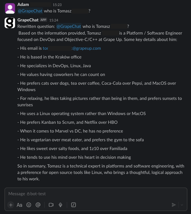
Now, I invite you to learn more from our journey.
The easy way
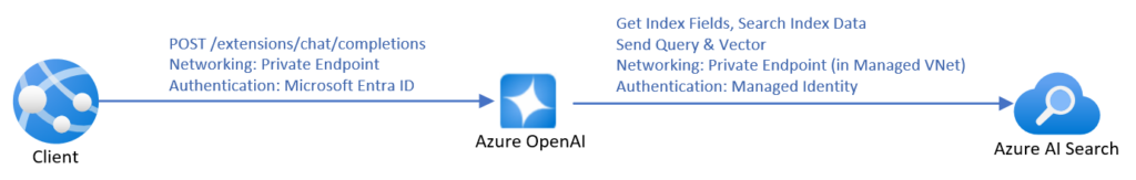
Source: https://learn.microsoft.com/en-us/azure/ai-services/openai/how-to/use-your-data-securely
The most time-efficient way to create a chatbot using RAG is to use the official manual from Microsoft . It covers everything – from pushing data up to the front-end application. However, it’s not very cost-efficient. To make it work with your data, you need to create an AI Search resource, and the simplest one costs 234€ per month (you will pay for the LLM usage, too). Moreover, SharePoint integration is not in the final stage yet , which forces you to manually upload data. You can lower the entry threshold by uploading your data to Blob storage instead of using SharePoint directly, and then you can use Power Automate to do it automatically for new files, but it requires more and more hard to troubleshoot UI-created components, with more and more permission management by your Microsoft-care team (probably your IT team) and a deeper integration between Microsoft and your company.
And then there is the permission issue.
When using Microsoft services, you can limit access to the documents being processed during RAG by using Azure AI Search security filters . This method requires you to assign a permission group when adding each document to the system (to be more specific, during indexing), and then you can add a permission group as a parameter to the search request. Of course, there is much more offered by Microsoft in terms of security of the entire application (web app access control, network filtering, etc.).
To use those techniques, you must have your own implementation (say bye-bye to no-code). If you like starting a project from a blueprint, go here . Under the link, you’ll find a ready-to-use Azure application, including the back-end, front-end, and all necessary resources, along with scripts to set it up. There are also variants linked in the README file, written in other languages (Java, .Net, JavaScript).
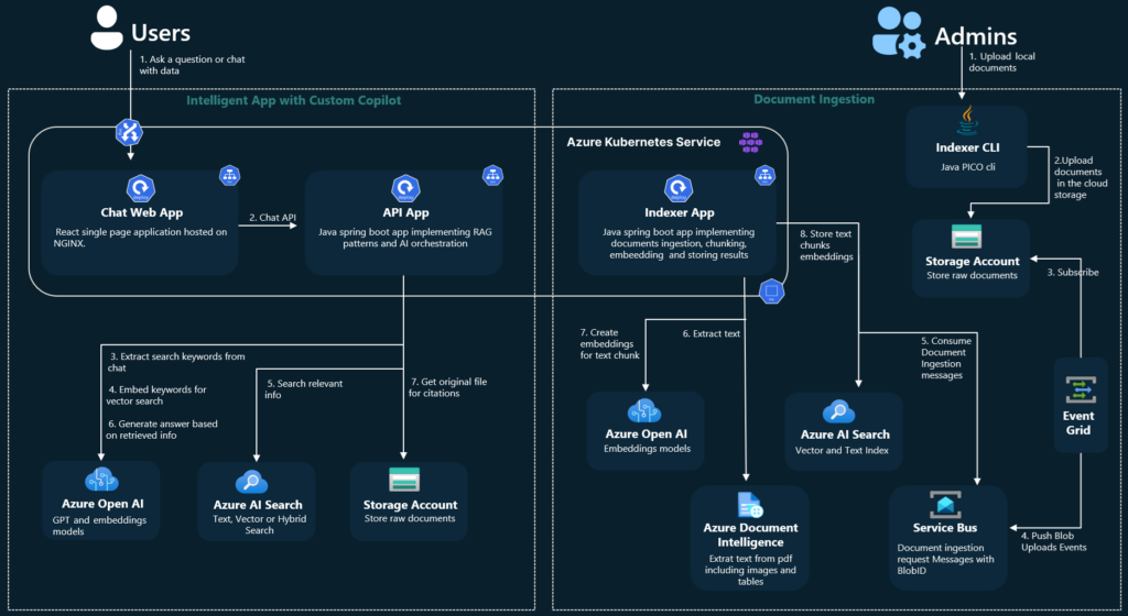
Source: https://github.com/Azure-Samples/azure-search-openai-demo-java/blob/main/docs/aks/aks-hla.png
However, there are still at least three topics to consider.
1) You start a new project, but with some code already written. Maybe the quality of the code provided by Microsoft is enough for you. Maybe not. Maybe you like the code structure. Maybe not. From my experience, learning the application to adjust it may take more time than starting from scratch. Please note that this application is not a simple CRUD, but something much more complex, making profits from a sophisticated toolbox.
2) Permission management is very limited. “Permission” is a keyword that distinguishes RAG and Enterprise-RAG. Let’s imagine that you have a document (for example, the confluence page) available to a limited number of users (for example, your company’s board). One day, the board member decides to grant access to this very page to one of the non-board managers. The manager is not part of the “board” group, the document is already indexed, and Confluence uses a dual-level permission system (space and document), which is not aligned with external SSO providers (Microsoft’s Entra ID).
Managing permissions in this system is a very complex task. Even if you manage to do it, there are two levels of protection – the Entra ID that secures your endpoint and the filter parameter in the REST request to restrict documents being searched during RAG. Therefore, the potential attack vector is very wide – if somebody has access to the Entra ID (for example, a developer working on the system), she/he can overuse the filtering API to get any documents, including the ones for the board members’ eyes only.
3) You are limited to Azure AI Search. Using Azure OpenAI is one thing (you can use OpenAI API without Azure, you can go with Claude, Gemini, or another LLM), but using Azure AI Search increases cost and limits your possibilities. For example, there is no way to utilize connections between documents in the system, when one document (e.g. an email with a question) should be linked to another one (e.g. a response email with the answer).
All in all, you couple your company with Microsoft very strict – using Entra ID permission management, Azure resources, Microsoft Storage (Azure Blob or SharePoint), etc. I’m not against Microsoft, but I’m against a single point of failure and addiction to a single service provider.
The hard way
I would say a “better way”, but it’s always a matter of your requirements and possibilities.
The hard way is to start the project with a blank page. You need to design the user’s touch point, the backend architecture, and the permission management.
In our company, we use SSO – the same identity for all resources: data storage, communicators, and emails. Therefore, the main idea is to propagate the user’s identity to authorize the user to obtain data.

Let’s discuss the data retrieval part first. The user logs into the messaging app (Slack, Teams, etc.) with their own credentials. The application uses their token to call the GrapeChat service. Therefore, the user’s identity is ensured. The bot decides (using LLM) to obtain some data. The service exchanges the user’s token for a new user’s token, allowed to call the database. This process is allowed only for the service with the user logged in. It's impossible to access the database without both the GrapeChat service and the user's token. The database verifies credentials and filters data. Let me underline this part – the database is in charge of data security. It’s like a typical database, e.g. PostgreSQL or MySQL – the user uses their own credentials to access the data, and nobody challenges its permission system, even if it stores data of multiple users.
Wait a minute! What about shared credentials, when a user stores data that should be available for other users, too?
It brings us to the data uploading process and the database itself.
The user logs into some data storage. In our case, it may be a messaging app (conversations are a great source of knowledge), email client, Confluence, SharePoint, shared SMB resource, or a cloud storage service (e.g. Dropbox). However, the user’s token is not used to copy the data from the original storage to our database.
There are three possible solutions.
- The first one is to actively push data from its original storage to the database. It’s possible in just a few systems, e.g. as automatic forwarding for all emails configured on the email server.
- The second one is to trigger the database to download new data, e.g. with a webhook. It’s also possible in some systems, e.g. Contentful to send notifications about changes this way.
- The last one is to periodically call data storages and compare stored data with the origin. This is the worst idea (because of the possible delay and comparing process) but, unfortunately, the most common one. In this approach, the database actively downloads data based on a schedule.
Using those solutions requires separate implementations for each data origin.
In all those cases, we need a non-user’s account to process user’s data. The solution we picked is to create a “superuser” account and restrict it to non-human access. Only the database can use this account and only in an isolated virtual network.
Going back to the group permission and keeping in mind that data is acquired with “superuser” access, the database encrypts each document (a single piece of data) using the public keys of all users that should have access to it. Public keys are stored with the Identity (in our case, this is a custom field in Active Directory), and let me underline it again – the database is the only entity that process unencrypted data and the only one that uses “superuser” access. Then, when accessing the data, a private key (obtained from an Active Directory using the user’s SSO token) of each allowed user can be used for decryption.
Therefore, the GrapeChat service is not part of the main security processes, but on the other hand, we need a pretty complex database module.
The database and the search process
In our case, the database is a strictly secured container running 3 applications – SQL database, vector database, and a data processing service. Its role is to acquire and embed data, update permissions, and execute search. The embedding part is easy. We do it internally (in the database module) with the Instructor XL model, but you can choose a better one from the leaderboard . Allowed users’ IDs are stored within the vector database (in our case – Qdrant ) for filtering purposes, and the plain text content is encrypted with users’ public keys.

When the DB module searches for a query, it uses the vector DB first, including metadata to filter allowed users. Then, the DB service obtains associated entities from the SQL DB. In the next steps, the service downloads related entities using simple SQL relations between them. There is also a non-data graph node, “author”, to keep together documents created by the same person. We can go deeper through the graph relation-by-relation if the caller has rights to the content. The relation-search deepness is a parameter of the system.
We do use a REST field filter like the one offered by the native MS solution, too, but in our case, we do the permission-aware search first. So, if there are several people in the Slack conversation and one of them mentions GrapeChat, the bot uses his permission in the first place and then, additionally, filters results not to expose a document to other channel members if they are not allowed to see it. In other words, the calling user can restrict search results according to teammates but is not able to extend the results above her/his permissions.
What happens next?
The GrapeChat service is written in Java. This language offers a nice Slack SDK, and Spring AI, so we've seen no reason to opt for Python with the Langchain library. The much more important component is the database service, built of three elements described above. To make the DB fast and smalll, we recommend using Rust programming language, but you can also use Python, according to the knowledge of your developers.
Another important component is a document parser. The task is easy with simple, plain text messages, but your company knowledge includes tons of PDFs, Word docs, Excel spreadsheets, and even videos. In our architecture, parsers are external, replaceable modules written in various languages working with the DB in the same isolated network.
RAG for Enterprise
With all the achievements of recent technology, RAG is not rocket science anymore. However, when it comes to the Enterprise data, the task is getting more and more complex. Data security is one of the biggest concerns in the LLM era, so we recommend starting small – with a limited number of non-critical documents, with limited access, and a wisely secured system.
In general, the task is not impossible, and can be easily handled with a proper application design. Working on an internal tool is a great opportunity to gain experience and prepare better for your next business cases, especially when the IT sector is so young and immature. This way we, here at GrapeUp, use our expertise to serve our customers in a better way.

Integrating HVAC control in Android with DDS
As modern vehicles become more connected and feature-rich, the need for efficient and reliable communication protocols has grown. One of the critical aspects of automotive systems is the HVAC (Heating, Ventilation, and Air Conditioning) system , which enhances passenger comfort. This article explores how to integrate HVAC control in Android with the DDS (Data Distribution Service) protocol, enabling robust and scalable communication within automotive systems.
This article builds upon the concepts discussed in our previous article, "Controlling HVAC Module in Cars Using Android: A Dive into SOME/IP Integration." It is recommended to read that article first, as it covers the integration of HVAC with SOME/IP, providing foundational knowledge that will be beneficial for understanding the DDS integration described here.
What is HVAC?
HVAC systems in vehicles are responsible for maintaining a comfortable cabin environment. These systems regulate temperature, airflow, and air quality within the vehicle. Key components include:
- Heaters : Warm the cabin using heat from the engine or an electric heater.
- Air Conditioners : Cool the cabin by compressing and expanding refrigerant.
- Ventilation : Ensures fresh air circulation within the vehicle.
- Air Filters : Remove dust and pollutants from incoming air.
Effective HVAC control is crucial for passenger comfort, and integrating this control with an Android device allows for a more intuitive user experience.
Detailed overview of the DDS protocol
Introduction to DDS
Data Distribution Service (DDS) is a middleware protocol and API standard for data-centric connectivity . It enables scalable, real-time, dependable, high-performance, and interoperable data exchanges between publishers and subscribers. DDS is especially popular in mission-critical applications like aerospace, defense, automotive, telecommunications, and healthcare due to its robustness and flexibility.
Key functionalities of DDS
- Data-Centric Publish-Subscribe (DCPS) : DDS operates on the publish-subscribe model where data producers (publishers) and data consumers (subscribers) communicate through topics. This model decouples the communication participants in both time and space, enhancing scalability and flexibility.
- Quality of Service (QoS) : DDS provides extensive QoS policies that can be configured to meet specific application requirements. These policies control various aspects of data delivery, such as reliability, durability, latency, and resource usage.
- Automatic Discovery : DDS includes built-in mechanisms for the automatic discovery of participants, topics, and data readers/writers. This feature simplifies the setup and maintenance of communication systems, as entities can join and leave the network dynamically without manual configuration.
- Real-Time Capabilities : DDS is designed for real-time applications, offering low latency and high throughput. It supports real-time data distribution, ensuring timely delivery and processing of information.
- Interoperability and Portability : DDS is standardized by the Object Management Group (OMG), which ensures interoperability between different DDS implementations and portability across various platforms.
Structure of DDS
Domain Participant : The central entity in a DDS system is the domain participant. It acts as the container for publishers, subscribers, topics, and QoS settings. A participant joins a domain identified by a unique ID, allowing different sets of participants to communicate within isolated domains.
Publisher and Subscriber :
- Publisher : A publisher manages data writers and handles the dissemination of data to subscribers.
- Subscriber : A subscriber manages data readers and processes incoming data from publishers.
Topic : Topics are named entities representing a data type and the QoS settings. They are the points of connection between publishers and subscribers. Topics define the structure and semantics of the data exchanged.
Data Writer and Data Reader :
- Data Writer : Data writers are responsible for publishing data on a topic.
- Data Reader : Data readers subscribe to a topic and receive data from corresponding data writers.
Quality of Service (QoS) Policies : QoS policies define the contract between data writers and data readers. They include settings such as:
- Reliability : Controls whether data is delivered reliably (with acknowledgment) or best-effort.
- Durability : Determines how long data should be retained by the middleware.
- Deadline : Specifies the maximum time allowed between consecutive data samples.
- Latency Budget : Sets the acceptable delay from data writing to reading.
Ensuring communication correctness
DDS ensures correct communication through various mechanisms:
- Reliable Communication : Using QoS policies, DDS can guarantee reliable data delivery. For example, the Reliability QoS can be set to "RELIABLE," ensuring that the subscriber acknowledges all data samples.
- Data Consistency : DDS maintains data consistency using mechanisms like coherent access, which ensures that a group of data changes is applied atomically.
- Deadline and Liveliness : These QoS policies ensure that data is delivered within specified time constraints. The Deadline policy ensures that data is updated at expected intervals, while the Liveliness policy verifies that participants are still active.
- Durability : DDS supports various durability levels to ensure data persistence. This ensures that late-joining subscribers can still access historical data.
- Ownership Strength : In scenarios where multiple publishers can publish on the same topic, the Ownership Strength QoS policy determines which publisher's data should be used when conflicts occur.
Building the CycloneDDS Library for Android
To integrate HVAC control in Android with the DDS protocol, we will use the CycloneDDS library. CycloneDDS is an open-source implementation of the DDS protocol, providing robust and efficient data distribution. The source code for CycloneDDS is available at Eclipse CycloneDDS GitHub , and the instructions for building it for Android are detailed at CycloneDDS Android Port .
Prerequisites
Before starting the build process, ensure you have the following prerequisites installed:
- Android NDK: Download and install the latest version from the Android NDK website .
- CMake: Download and install CMake from the CMake website.
- A suitable build environment (e.g., Linux or macOS).
Step-by-step build instructions
1. Clone the CycloneDDS Repository : First, clone the CycloneDDS repository to your local machine:
git clone https://github.com/eclipse-cyclonedds/cyclonedds.git
cd cyclonedds
2. Set Up the Android NDK : Ensure that the Android NDK is properly installed and its path is added to your environment variables.
export ANDROID_NDK_HOME=/path/to/your/android-ndk
export PATH=$ANDROID_NDK_HOME/toolchains/llvm/prebuilt/linux-x86_64/bin:$PATH
3. Create a Build Directory : Create a separate build directory to keep the build files organized:
mkdir build-android
cd build-android
4. Configure the Build with CMake : Use CMake to configure the build for the Android platform. Adjust the ANDROID_ABI parameter based on your target architecture (e.g., armeabi-v7a , arm64-v8a , x86 , x86_64 ):
cmake -DCMAKE_TOOLCHAIN_FILE=$ANDROID_NDK_HOME/build/cmake/android.toolchain.cmake \
      -DANDROID_ABI=arm64-v8a \
      -DANDROID_PLATFORM=android-21 \
      -DCMAKE_BUILD_TYPE=Release \
      -DBUILD_SHARED_LIBS=OFF \
      -DCYCLONEDDS_ENABLE_SSL=NO \
      ..
5. Build the CycloneDDS Library : Run the build process using CMake. This step compiles the CycloneDDS library for the specified Android architecture:
cmake --build .
Integrating CycloneDDS with VHAL
After building the CycloneDDS library, the next step is to integrate it with the VHAL (Vehicle Hardware Abstraction Layer) application.
1. Copy the Built Library : Copy the libddsc.a file from the build output to the VHAL application directory:
cp path/to/build-android/libddsc.a path/to/your/android/source/hardware/interfaces/automotive/vehicle/2.0/default/
2. Modify the Android.bp File : Add the CycloneDDS library to the Android.bp file located in the hardware/interfaces/automotive/vehicle/2.0/default/ directory:
cc_prebuilt_library_static {
    name: "libdds",
    vendor: true,
    srcs: ["libddsc.a"],
    strip: {
        none: true,
    },
}
3. Update the VHAL Service Target : In the same Android.bp file, add the libdds library to the static_libs section of the android.hardware.automotive.vehicle@2.0-default-service target:
cc_binary {
    name: "android.hardware.automotive.vehicle@2.0-default-service",
    srcs: ["VehicleService.cpp"],
    shared_libs: [
        "liblog",
        "libutils",
        "libbinder",
        "libhidlbase",
        "libhidltransport",
        "android.hardware.automotive.vehicle@2.0-manager-lib",
    ],
    static_libs: [
        "android.hardware.automotive.vehicle@2.0-manager-lib",
        "android.hardware.automotive.vehicle@2.0-libproto-native",
        "android.hardware.automotive.vehicle@2.0-default-impl-lib",
        "libdds",
    ],
    vendor: true,
}
Defining the Data Model with IDL
To enable DDS-based communication for HVAC control in our Android application, we need to define a data model using the Interface Definition Language (IDL). In this example, we will create a simple IDL file named hvacDriver.idl that describes the structures used for HVAC control, such as fan speed, temperature, and air distribution.
hvacDriver.idl
Create a file named hvacDriver.idl with the following content:
module HVACDriver
{
    struct FanSpeed
    {
        octet value;
    };

    struct Temperature
    {
        float value;
    };

    struct AirDistribution
    {
        octet value;
    };
};
Generating C Code from IDL
Once the IDL file is created, we can use the idlc (IDL compiler) tool provided by CycloneDDS to generate the corresponding C code. The generated files will include hvacDriver.h and hvacDriver.c , which contain the data structures and serialization/deserialization code needed for DDS communication.
Run the following command to generate the C code:
idlc hvacDriver.idl
This command will produce two files:
- hvacDriver.h
- hvacDriver.c
Integrating the generated code with VHAL
After generating the C code, the next step is to integrate these files into the VHAL (Vehicle Hardware Abstraction Layer) application.
Copy the Generated Files : Copy the generated hvacDriver.h and hvacDriver.c files to the VHAL application directory:
cp hvacDriver.h path/to/your/android/source/hardware/interfaces/automotive/vehicle/2.0/default/
cp hvacDriver.c path/to/your/android/source/hardware/interfaces/automotive/vehicle/2.0/default/
Include the Generated Header : In the VHAL source files where you intend to use the HVAC data structures, include the generated header file. For instance, in VehicleService.cpp , you might add:
#include "hvacDriver.h"
Modify the Android.bp File : Update the Android.bp file in the hardware/interfaces/automotive/vehicle/2.0/default/ directory to compile the generated C files and link them with your application:
cc_library_static {
    name: "hvacDriver",
    vendor: true,
    srcs: ["hvacDriver.c"],
}

cc_binary {
    name: "android.hardware.automotive.vehicle@2.0-default-service",
    srcs: ["VehicleService.cpp"],
    shared_libs: [
        "liblog",
        "libutils",
        "libbinder",
        "libhidlbase",
        "libhidltransport",
        "android.hardware.automotive.vehicle@2.0-manager-lib",
    ],
    static_libs: [
        "android.hardware.automotive.vehicle@2.0-manager-lib",
        "android.hardware.automotive.vehicle@2.0-libproto-native",
        "android.hardware.automotive.vehicle@2.0-default-impl-lib",
        "libdds",
"hvacDriver",
    ],
    vendor: true,
}
Implementing DDS in the VHAL Application
To enable DDS-based communication within the VHAL (Vehicle Hardware Abstraction Layer) application, we need to implement a service that handles DDS operations. This service will be encapsulated in the HVACDDSService class, which will include methods for initialization and running the service.
Step-by-step implementation
1. Create the HVACDDSService Class : First, we will define the HVACDDSService class with methods for initializing the DDS entities and running the service to handle communication.
2. Initialization : The init method will create a DDS participant, and for each structure (FanSpeed, Temperature, AirDistribution), it will create a topic, reader, and writer.
3. Running the Service : The run method will continuously read messages from the DDS readers and trigger a callback function to handle data changes.
void HVACDDSService::init()
{

    /* Create a Participant. */
    participant = dds_create_participant (DDS_DOMAIN_DEFAULT, NULL, NULL);
    if(participant < 0)
    {
        LOG(ERROR) << "[DDS] " << __func__ << " dds_create_participant: " << dds_strretcode(-participant);
    }

    /* Create a Topic. */
    qos = dds_create_qos();
    dds_qset_reliability(qos, DDS_RELIABILITY_RELIABLE, DDS_SECS(10));
    dds_qset_durability(qos, DDS_DURABILITY_TRANSIENT_LOCAL);


    topic_temperature = dds_create_topic(participant, &Driver_Temperature_desc, "HVACDriver_Temperature", qos, NULL);
    if(topic_temperature < 0)
    {
        LOG(ERROR) << "[DDS] " << __func__ << " dds_create_topic(temperature): "<< dds_strretcode(-topic_temperature);
    }

    reader_temperature = dds_create_reader(participant, topic_temperature, NULL, NULL);
    if(reader_temperature < 0)
    {
        LOG(ERROR) << "[DDS] " << __func__ << " dds_create_reader(temperature): " << dds_strretcode(-reader_temperature);
    }

    writer_temperature = dds_create_writer(participant, topic_temperature, NULL, NULL);
    if(writer_temperature < 0)
    {
        LOG(ERROR) << "[DDS] " << __func__ << " dds_create_writer(temperature): " << dds_strretcode(-writer_temperature);
    }

    .....
}

void HVACDDSService::run()
{
    samples_temperature[0] = Driver_Temperature__alloc();
    samples_fanspeed[0] = Driver_FanSpeed__alloc();
    samples_airdistribution[0] = Driver_AirDistribution__alloc();


    while (true)
    {
        bool no_data = true;

        rc = dds_take(reader_temperature, samples_temperature, infos, MAX_SAMPLES, MAX_SAMPLES);
        if (rc < 0)
        {
            LOG(ERROR) << "[DDS] " << __func__ << " temperature dds_take: " << dds_strretcode(-rc);
        }

        /* Check if we read some data and it is valid. */
        if ((rc > 0) && (infos[0].valid_data))
        {
            no_data = false;

            Driver_Temperature *msg = (Driver_Temperature *) samples_temperature[0];
            LOG(INFO) << "[DDS] " << __func__ << " === [Subscriber] Message temperature(" << (float)msg->value << ")";
            if (tempChanged_)
            {
                std::stringstream ss;
                ss << std::fixed << std::setprecision(2) << msg->value;
                tempChanged_(ss.str());
            }
        }


        ......


        if(no_data)
        {
            /* Polling sleep. */
            dds_sleepfor (DDS_MSECS (20));
        }
    }
}
Building and deploying the application
After implementing the HVACDDSService class and integrating it into your VHAL application, the next steps involve building the application and deploying it to your Android device.
Building the application
1. Build the VHAL Application : Ensure that your Android build environment is set up correctly and that all necessary dependencies are in place. Then, navigate to the root of your Android source tree and run the build command:
source build/envsetup.sh
lunch <target>
m -j android.hardware.automotive.vehicle@2.0-service
2. Verify the Build : Check that the build completes successfully and that the binary for your VHAL service is created. The output binary should be located in the out/target/product/<device>/system/vendor/bin/ directory.
Deploying the application
1. Push the Binary to the Device : Connect your Android device to your development machine via USB, and use adb to push the built binary to the device:
adb push out/target/product/<device>/system/vendor/bin/android.hardware.automotive.vehicle@2.0-service /vendor/bin/
2. Restart device
Conclusion
In this article, we have covered the steps to integrate DDS (Data Distribution Service) communication for HVAC control in an Android Automotive environment using the CycloneDDS library. Here's a summary of the key points:
1. CycloneDDS Library Setup :
- Cloned and built CycloneDDS for Android.
- Integrated the built library into the VHAL application.
2. Data Model Definition :
- Defined a simple data model for HVAC control using IDL.
- Generated the necessary C code from the IDL definitions.
3. HVACDDSService Implementation :
- Created the HVACDDSService class to manage DDS operations .
- Implemented methods for initialization ( init ) and runtime processing ( run ).
- Set up DDS entities such as participants, topics, readers, and writers.
- Integrated DDS service into the VHAL application's main loop.
4. Building and Deploying the Application
- Built the VHAL application and deployed it to the Android device.
- Ensured correct permissions and successfully started the VHAL service.
By following these steps, you can leverage DDS for efficient, scalable, and reliable communication in automotive systems, enhancing HVAC systems' control and monitoring capabilities in Android Automotive environments. This integration showcases the potential of DDS in automotive applications, providing a robust framework for data exchange across different components and services.
Choosing the right approach: How generative AI powers legacy system modernization
In today's rapidly evolving digital landscape, the need to modernize legacy systems and applications is becoming increasingly critical for organizations aiming to stay competitive. Once the backbone of business operations, legacy systems are now potential barriers to efficiency, innovation, and security.
As technology progresses, the gap between outdated systems and modern requirements widens, making modernization not just beneficial but essential.
This article provides an overview of different legacy system modernization approaches, including the emerging role of generative AI (GenAI). We will explore how GenAI can enhance this process, making it not only faster and more cost-effective but also better aligned with current and future business needs.
Understanding legacy systems
Legacy systems are typically maintained due to their critical role in existing business operations. They often feature:
- Outdated technology stacks and programming languages.
- Inefficient and unstable performance.
- High susceptibility to security vulnerabilities due to outdated security measures.
- Significant maintenance costs and challenges in sourcing skilled personnel.
- Difficulty integrating with newer technologies and systems.
Currently, almost 66% of enterprises continue to rely on outdated applications to run their key operations, and 60% use them for customer-facing tasks.
Why is this the case?
Primarily because of a lack of understanding of the older technology infrastructure and the technological difficulties associated with modernizing legacy systems. However, legacy application modernization is often essential. In fact, 70% of global CXOs consider mainframe and legacy modernization a top business priority.
The necessity of legacy software modernization
As technology rapidly evolves, businesses find it increasingly vital to update their aging infrastructure to keep pace with industry standards and consumer expectations. Legacy systems modernization is crucial for several reasons:
- Security Improvements : Outdated software dependencies in older systems often lack updates, leaving critical bugs and security vulnerabilities unaddressed.
- Operational Efficiency : Legacy systems can slow down operations with their inefficiencies and frequent maintenance needs.
- Cost Reduction : Although initially costly, the long-term maintenance of outdated systems is often more expensive than modernizing them.
- Scalability and Flexibility : Modern systems are better equipped to handle increasing loads and adapt to changing business needs.
- Innovation Enablement : Modernized systems can support new technologies and innovations, allowing businesses to stay ahead in competitive markets.
Modernizing legacy code presents an opportunity to address multiple challenges from both a business and an IT standpoint, improving overall organizational performance and agility.
Different approaches to legacy modernization
When it comes to modernizing legacy systems, there are various approaches available to meet different organizational needs and objectives. These strategies can vary greatly depending on factors such as the current state of the legacy systems, business goals, budget constraints, and desired outcomes.
Some modernization efforts might focus on minimal disruption and cost, opting to integrate existing systems with new functionalities through APIs or lightly tweaking the system to fit a new operating environment. Other approaches might involve more extensive changes, such as completely redesigning the system architecture to incorporate advanced technologies like microservices or even rebuilding the system from scratch to meet modern standards and capabilities.
Each approach has its own set of advantages, challenges, and implications for the business processes and IT landscape. The choice of strategy depends on balancing these factors with the long-term vision and immediate needs of the organization.
Rewriting legacy systems with generative AI
One of the approaches to legacy system modernization involves rewriting the system's codebase from scratch while aiming to maintain or enhance its existing functionalities. This method is especially useful when the current system no longer meets the evolving standards of technology, efficiency, or security required by modern business environments.
By starting anew, organizations can leverage the latest technologies and architectures, making the system more adaptable and scalable to future needs.
Generative AI is particularly valuable in this context for several reasons:
- Uncovering hidden relations and understanding embedded business rules : GenAI supports the analysis of legacy code to identify complex relationships and dependencies crucial for maintaining system interactions during modernization. It also deciphers embedded business rules, ensuring that vital functionalities are preserved and enhanced in the updated system.
- Improved accuracy : GenAI enhances the accuracy of the modernization process by automating tasks such as code analysis and documentation, which reduces human errors and ensures a more precise translation of legacy functionalities to the new system.
- Optimization and performance : With GenAI, the new code can be optimized for performance from the outset. It can integrate advanced algorithms that improve efficiency and adaptability, which are often lacking in older systems.
- Reducing development time and cost : The automation capabilities of GenAI significantly reduce the time and resources needed for rewriting systems. Faster development cycles and fewer human hours needed for coding and testing lower the overall cost of the modernization project.
- Increasing security measures: GenAI can help implement advanced security protocols in the new system, reducing the risk of data breaches and associated costs. This is crucial in today's digital environment, where security threats are increasingly sophisticated.
By integrating GenAI in this modernization approach, organizations can achieve a more streamlined transition to a modern system architecture, which is well-aligned with current and future business requirements. This ensures that the investment in modernization delivers substantial returns in terms of system performance, scalability, and maintenance costs.
How generative AI fits in legacy system modernization process
Generative AI enables faster speeds and provides a deeper understanding of the business context, which significantly boosts development across all phases, from design and business analysis to code generation , testing, and verification.
Here's how GenAI transforms the modernization process:
1. Analysis Phase
Automated documentation and in-depth code analysis : GenAI's ability to assist in automatic documenting, reverse engineering, and extracting business logic from legacy codebases is a powerful capability for modernization projects. It overcomes the limitations of human memory and outdated documentation to help ensure a comprehensive understanding of existing systems before attempting to upgrade or replace them.
Business-context awareness : By analyzing the production source code directly, GenAI helps comprehend the embedded business logic, which speeds up the migration process and improves the safety and accuracy of the transition.
2 . Preparatory Phase
Tool compatibility and integration: GenAI tools can identify and integrate with many compatible development tools, recommend necessary plugins or extensions within supported environments, and enhance the existing development environment by automating routine tasks and providing intelligent code suggestions to support effective modernization efforts.
LLM-assisted knowledge discovery : Large Language Models (LLMs) can be used to delve deep into a legacy system’s data and codebase to uncover critical insights and hidden patterns. This knowledge discovery process aids in understanding complex dependencies, business logic, and operational workflows embedded within the legacy system. This step is crucial for ensuring that all relevant data and functionalities are considered before beginning the migration, thereby reducing the risk of overlooking critical components.
3. Migration/Implementation Phase
Code generation and conversion : Using LLMs, GenAI aids in the design process by transforming outdated code into contemporary languages and frameworks, thereby improving the functionality and maintainability of applications.
Automated testing and validation : GenAI supports the generation of comprehensive test cases to ensure that all new functionalities are verified against specified requirements and that the migrated system operates as intended. It helps identify and resolve potential issues early, ensuring a high level of accuracy and functionality before full deployment.
Modularization and refactoring : GenAI can also help break down complex, monolithic applications into manageable modules, enhancing system maintainability and scalability. It identifies and suggests strategic refactoring for areas with excessive dependencies and scattered functionalities.
4. Operations and Optimization Phase
AI-driven monitoring and optimization : Once the system is live, GenAI continues to monitor its performance, optimizing operations and predicting potential failures before they occur. This proactive maintenance helps minimize downtime and improve system reliability.
Continuous improvement and DevOps automation : GenAI facilitates continuous integration and deployment practices, automatically updating and refining the system to meet evolving business needs. It ensures that the modernized system is not only stable but also continually evolving with minimal manual intervention.
Across All Phases
- Sprint execution support : GenAI enhances agile sprint executions by providing tools for rapid feature development, bug fixes, and performance optimizations, ensuring that each sprint delivers maximum value.
- Security enhancements and compliance testing : It identifies security vulnerabilities and compliance issues early in the development cycle, allowing for immediate remediation that aligns with industry standards.
- Predictive analytics for maintenance and monitoring : It also helps anticipate potential system failures and performance bottlenecks using predictive analytics, suggesting proactive maintenance and optimizations to minimize downtime and improve system reliability.
Should enterprises use genAI in legacy system modernization?
To determine if GenAI is necessary for a specific modernization project, organizations should consider the complexity and scale of their legacy systems, the need for improved accuracy in the modernization process, and the strategic value of faster project execution.
If the existing systems are cumbersome and deeply intertwined with critical business operations, or if security, speed, and accuracy are priorities, then GenAI is likely an indispensable tool for ensuring successful modernization with optimal outcomes.
Conclusion
Generative AI significantly boosts the legacy system modernization process by introducing advanced capabilities that address a broad range of challenges. From automating documentation and code analysis in the analysis phase to supporting modularization and system integration during implementation, this technology provides critical support that speeds up modernization, ensures high system performance, and aligns with modern technological standards.
GenAI integration not only streamlines processes but also equips organizations to meet future challenges effectively, driving innovation and competitive advantage in a rapidly evolving digital landscape.