AAOS 14 - Surround view parking camera: How to configure and launch exterior view system

EVS - park mode
The Android Automotive Operating System (AAOS) 14 introduces significant advancements, including a Surround View Parking Camera system. This feature, part of the Exterior View System (EVS), provides a comprehensive 360-degree view around the vehicle, enhancing parking safety and ease. This article will guide you through the process of configuring and launching the EVS on AAOS 14 .
Structure of the EVS system in Android 14
The Exterior View System (EVS) in Android 14 is a sophisticated integration designed to enhance driver awareness and safety through multiple external camera feeds. This system is composed of three primary components: the EVS Driver application, the Manager application, and the EVS App. Each component plays a crucial role in capturing, managing, and displaying the images necessary for a comprehensive view of the vehicle's surroundings.
EVS driver application
The EVS Driver application serves as the cornerstone of the EVS system, responsible for capturing images from the vehicle's cameras. These images are delivered as RGBA image buffers, which are essential for further processing and display. Typically, the Driver application is provided by the vehicle manufacturer, tailored to ensure compatibility with the specific hardware and camera setup of the vehicle.
To aid developers, Android 14 includes a sample implementation of the Driver application that utilizes the Linux V4L2 (Video for Linux 2) subsystem. This example demonstrates how to capture images from USB-connected cameras, offering a practical reference for creating compatible Driver applications. The sample implementation is located in the Android source code at packages/services/Car/cpp/evs/sampleDriver .
Manager application
The Manager application acts as the intermediary between the Driver application and the EVS App. Its primary responsibilities include managing the connected cameras and displays within the system.
Key Tasks :
- Camera Management : Controls and coordinates the various cameras connected to the vehicle.
- Display Management : Manages the display units, ensuring the correct images are shown based on the input from the Driver application.
- Communication : Facilitates communication between the Driver application and the EVS App, ensuring a smooth data flow and integration.
EVS app
The EVS App is the central component of the EVS system, responsible for assembling the images from the various cameras and displaying them on the vehicle's screen. This application adapts the displayed content based on the vehicle's gear selection, providing relevant visual information to the driver.
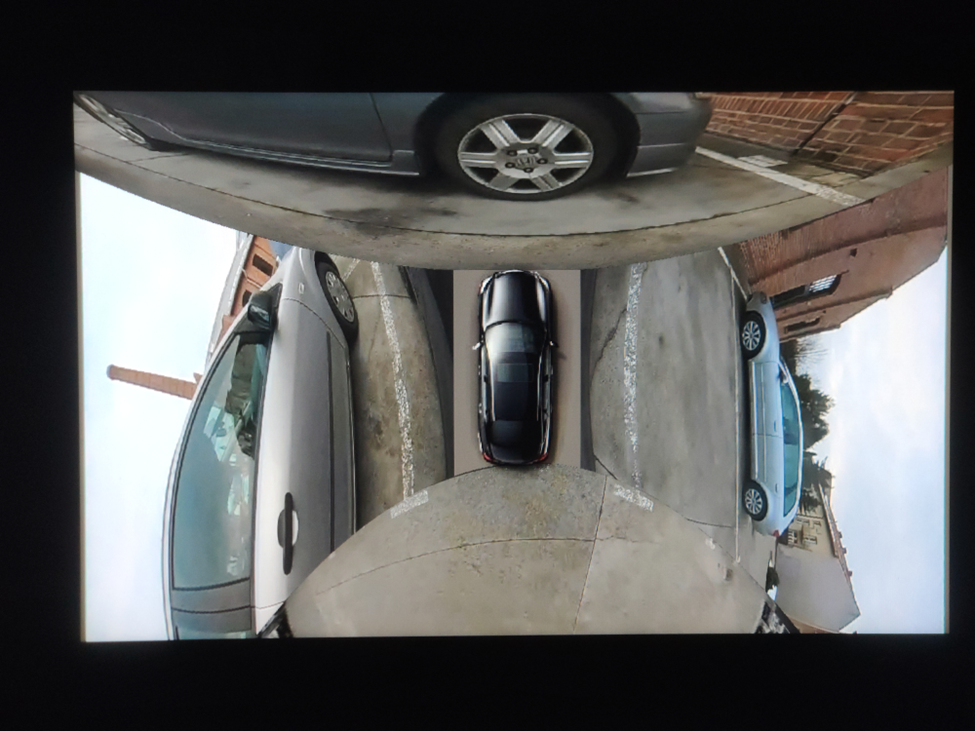
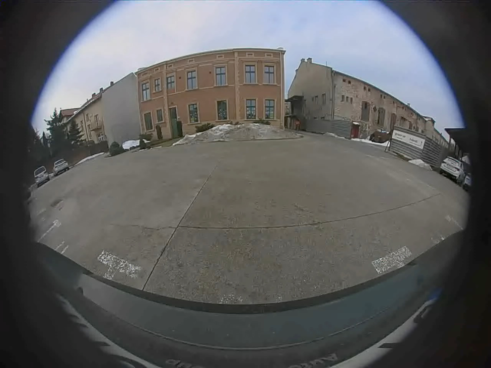
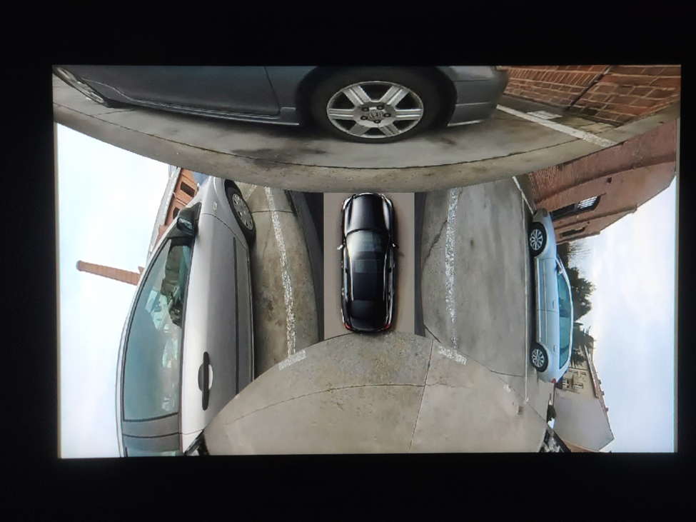
For instance, when the vehicle is in reverse gear (VehicleGear::GEAR_REVERSE), the EVS App displays the rear camera feed to assist with reversing maneuvers. When the vehicle is in park gear (VehicleGear::GEAR_PARK), the app showcases a 360-degree view by stitching images from four cameras, offering a comprehensive overview of the vehicle’s surroundings. In other gear positions, the EVS App stops displaying images and remains in the background, ready to activate when the gear changes again.
The EVS App achieves this dynamic functionality by subscribing to signals from the Vehicle Hardware Abstraction Layer (VHAL), specifically the VehicleProperty::GEAR_SELECTION . This allows the app to adjust the displayed content in real-time based on the current gear of the vehicle.
Communication interface
Communication between the Driver application, Manager application, and EVS App is facilitated through the IEvsEnumerator HAL interface. This interface plays a crucial role in the EVS system, ensuring that image data is captured, managed, and displayed accurately. The IEvsEnumerator interface is defined in the Android source code at hardware/interfaces/automotive/evs/1.0/IEvsEnumerator.hal .
EVS subsystem update
Evs source code is located in: packages/services/Car/cpp/evs. Please make sure you use the latest sources because there were some bugs in the later version that cause Evs to not work.
cd  packages/services/Car/cpp/evs
git checkout main
git pull
mm
adb push out/target/product/rpi4/vendor/bin/hw/android.hardware.automotive.evs-default /vendor/bin/hw/
adb push out/target/product/rpi4/system/bin/evs_app /system/bin/
EVS driver configuration
To begin, we need to configure the EVS Driver. The configuration file is located at /vendor/etc/automotive/evs/evs_configuration_override.xml .
Here is an example of its content:
<configuration>
    <!-- system configuration -->
    <system>
        <!-- number of cameras available to EVS -->
        <num_cameras value='2'/>
    </system>

    <!-- camera device information -->
    <camera>

        <!-- camera device starts -->
        <device id='/dev/video0' position='rear'>
            <caps>
                <!-- list of supported controls -->
                <supported_controls>
                    <control name='BRIGHTNESS' min='0' max='255'/>
                    <control name='CONTRAST' min='0' max='255'/>
                    <control name='AUTO_WHITE_BALANCE' min='0' max='1'/>
                    <control name='WHITE_BALANCE_TEMPERATURE' min='2000' max='7500'/>
                    <control name='SHARPNESS' min='0' max='255'/>
                    <control name='AUTO_FOCUS' min='0' max='1'/>
                    <control name='ABSOLUTE_FOCUS' min='0' max='255' step='5'/>
                    <control name='ABSOLUTE_ZOOM' min='100' max='400'/>
                </supported_controls>

                <!-- list of supported stream configurations -->
                <!-- below configurations were taken from v4l2-ctrl query on
                     Logitech Webcam C930e device -->
                <stream id='0' width='1280' height='720' format='RGBA_8888' framerate='30'/>
            </caps>

            <!-- list of parameters -->
            <characteristics>

            </characteristics>
        </device>
        <device id='/dev/video2' position='front'>
            <caps>
                <!-- list of supported controls -->
                <supported_controls>
                    <control name='BRIGHTNESS' min='0' max='255'/>
                    <control name='CONTRAST' min='0' max='255'/>
                    <control name='AUTO_WHITE_BALANCE' min='0' max='1'/>
                    <control name='WHITE_BALANCE_TEMPERATURE' min='2000' max='7500'/>
                    <control name='SHARPNESS' min='0' max='255'/>
                    <control name='AUTO_FOCUS' min='0' max='1'/>
                    <control name='ABSOLUTE_FOCUS' min='0' max='255' step='5'/>
                    <control name='ABSOLUTE_ZOOM' min='100' max='400'/>
                </supported_controls>

                <!-- list of supported stream configurations -->
                <!-- below configurations were taken from v4l2-ctrl query on
                     Logitech Webcam C930e device -->
                <stream id='0' width='1280' height='720' format='RGBA_8888' framerate='30'/>
            </caps>

            <!-- list of parameters -->
            <characteristics>

            </characteristics>
        </device>
    </camera>

    <!-- display device starts -->
    <display>
        <device id='display0' position='driver'>
            <caps>
                <!-- list of supported inpu stream configurations -->
                <stream id='0' width='1280' height='800' format='RGBA_8888' framerate='30'/>
            </caps>
        </device>
    </display>
</configuration>
In this configuration, two cameras are defined: /dev/video0 (rear) and /dev/video2 (front). Both cameras have one stream defined with a resolution of 1280 x 720, a frame rate of 30, and an RGBA format.
Additionally, there is one display defined with a resolution of 1280 x 800, a frame rate of 30, and an RGBA format.
Configuration details
The configuration file starts by specifying the number of cameras available to the EVS system. This is done within the <system> tag, where the <num_cameras> tag sets the number of cameras to 2.
Each camera device is defined within the <camera> tag. For example, the rear camera ( /dev/video0 ) is defined with various capabilities such as brightness, contrast, auto white balance, and more. These capabilities are listed under the <supported_controls> tag. Similarly, the front camera ( /dev/video2 ) is defined with the same set of controls.
Both cameras also have their supported stream configurations listed under the <stream> tag. These configurations specify the resolution, format, and frame rate of the video streams.
The display device is defined under the <display> tag. The display configuration includes supported input stream configurations, specifying the resolution, format, and frame rate.
EVS driver operation
When the EVS Driver starts, it reads this configuration file to understand the available cameras and display settings. It then sends this configuration information to the Manager application. The EVS Driver will wait for requests to open and read from the cameras, operating according to the defined configurations.
EVS app configuration
Configuring the EVS App is more complex. We need to determine how the images from individual cameras will be combined to create a 360-degree view. In the repository, the file packages/services/Car/cpp/evs/apps/default/res/config.json.readme contains a description of the configuration sections:
{
  "car" : {                     // This section describes the geometry of the car
    "width"  : 76.7,            // The width of the car body
    "wheelBase" : 117.9,        // The distance between the front and rear axles
    "frontExtent" : 44.7,       // The extent of the car body ahead of the front axle
    "rearExtent" : 40           // The extent of the car body behind the rear axle
  },
  "displays" : [                // This configures the dimensions of the surround view display
    {                           // The first display will be used as the default display
      "displayPort" : 1,        // Display port number, the target display is connected to
      "frontRange" : 100,       // How far to render the view in front of the front bumper
      "rearRange" : 100         // How far the view extends behind the rear bumper
    }
  ],
  "graphic" : {                 // This maps the car texture into the projected view space
    "frontPixel" : 23,          // The pixel row in CarFromTop.png at which the front bumper appears
    "rearPixel" : 223           // The pixel row in CarFromTop.png at which the back bumper ends
  },
  "cameras" : [                 // This describes the cameras potentially available on the car
    {
      "cameraId" : "/dev/video32",  // Camera ID exposed by EVS HAL
      "function" : "reverse,park",  // Set of modes to which this camera contributes
      "x" : 0.0,                    // Optical center distance right of vehicle center
      "y" : -40.0,                  // Optical center distance forward of rear axle
      "z" : 48,                     // Optical center distance above ground
      "yaw" : 180,                  // Optical axis degrees to the left of straight ahead
      "pitch" : -30,                // Optical axis degrees above the horizon
      "roll" : 0,                   // Rotation degrees around the optical axis
      "hfov" : 125,                 // Horizontal field of view in degrees
      "vfov" : 103,                 // Vertical field of view in degrees
      "hflip" : true,               // Flip the view horizontally
      "vflip" : true                // Flip the view vertically
    }
  ]
}
The EVS app configuration file is crucial for setting up the system for a specific car. Although the inclusion of comments makes this example an invalid JSON, it serves to illustrate the expected format of the configuration file. Additionally, the system requires an image named CarFromTop.png to represent the car.
In the configuration, units of length are arbitrary but must remain consistent throughout the file. In this example, units of length are in inches.
The coordinate system is right-handed: X represents the right direction, Y is forward, and Z is up, with the origin located at the center of the rear axle at ground level. Angle units are in degrees, with yaw measured from the front of the car, positive to the left (positive Z rotation). Pitch is measured from the horizon, positive upwards (positive X rotation), and roll is always assumed to be zero. Please keep in mind that, unit of angles are in degrees, but they are converted to radians during configuration reading. So, if you want to change it in EVS App source code, use radians.
This setup allows the EVS app to accurately interpret and render the camera images for the surround view parking system.
The configuration file for the EVS App is located at /vendor/etc/automotive/evs/config_override.json . Below is an example configuration with two cameras, front and rear, corresponding to our driver setup:
{
  "car": {
    "width": 76.7,
    "wheelBase": 117.9,
    "frontExtent": 44.7,
    "rearExtent": 40
  },
  "displays": [
    {
      "_comment": "Display0",
      "displayPort": 0,
      "frontRange": 100,
      "rearRange": 100
    }
  ],
  "graphic": {
    "frontPixel": -20,
    "rearPixel": 260
  },
  "cameras": [
    {
      "cameraId": "/dev/video0",
      "function": "reverse,park",
      "x": 0.0,
      "y": 20.0,
      "z": 48,
      "yaw": 180,
      "pitch": -10,
      "roll": 0,
      "hfov": 115,
      "vfov": 80,
      "hflip": false,
      "vflip": false
    },
    {
      "cameraId": "/dev/video2",
      "function": "front,park",
      "x": 0.0,
      "y": 100.0,
      "z": 48,
      "yaw": 0,
      "pitch": -10,
      "roll": 0,
      "hfov": 115,
      "vfov": 80,
      "hflip": false,
      "vflip": false
    }
  ]
}
Running EVS
Make sure all apps are running:
ps -A | grep evs
automotive_evs 3722    1   11007600   6716 binder_thread_read  0 S evsmanagerd
graphics      3723     1   11362488  30868 binder_thread_read  0 S android.hardware.automotive.evs-default
automotive_evs 3736    1   11068388   9116 futex_wait          0 S evs_app
To simulate reverse gear you can call:
evs_app --test --gear reverse
And park:
evs_app --test --gear park
EVS app should be displayed on the screen.
Troubleshooting
When configuring and launching the EVS (Exterior View System) for the Surround View Parking Camera in Android AAOS 14, you may encounter several issues.
To debug that, you can use logs from EVS system:
logcat EvsDriver:D EvsApp:D evsmanagerd:D *:S
Multiple USB cameras - image freeze
During the initialization of the EVS system, we encountered an issue with the image feed from two USB cameras. While the feed from one camera displayed smoothly, the feed from the second camera either did not appear at all or froze after displaying a few frames.
We discovered that the problem lay in the USB communication between the camera and the V4L2 uvcvideo driver. During the connection negotiation, the camera reserved all available USB bandwidth. To prevent this, the uvcvideo driver needs to be configured with the parameter quirks=128 . This setting allows the driver to allocate the USB bandwidth based on the actual resolution and frame rate of the camera.
To implement this solution, the parameter should be set in the bootloader, within the kernel command line, for example:
console=ttyS0,115200 no_console_suspend root=/dev/ram0 rootwait androidboot.hardware=rpi4 androidboot.selinux=permissive uvcvideo.quirks=128
After applying this setting, the image feed from both cameras should display smoothly, resolving the freezing issue.
Green frame around camera image
In the current implementation of the EVS system, the camera image is surrounded by a green frame, as illustrated in the following image:
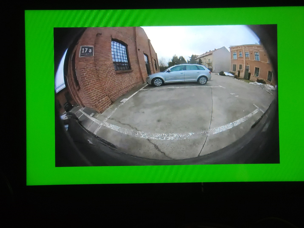
To eliminate this green frame, you need to modify the implementation of the EVS Driver. Specifically, you should edit the GlWrapper.cpp file located at cpp/evs/sampleDriver/aidl/src/ .
In the void GlWrapper::renderImageToScreen() function, change the following lines:
-0.8, 0.8, 0.0f, // left top in window space
 0.8, 0.8, 0.0f, // right top
-0.8, -0.8, 0.0f, // left bottom
 0.8, -0.8, 0.0f // right bottom
to
-1.0,  1.0, 0.0f,  // left top in window space
 1.0,  1.0, 0.0f,  // right top
-1.0, -1.0, 0.0f,  // left bottom
 1.0, -1.0, 0.0f   // right bottom
After making this change, rebuild the EVS Driver and deploy it to your device. The camera image should now be displayed full screen without the green frame.
Conclusion
In this article, we delved into the intricacies of configuring and launching the EVS (Exterior View System) for the Surround View Parking Camera in Android AAOS 14. We explored the critical components that make up the EVS system: the EVS Driver, EVS Manager, and EVS App, detailing their roles and interactions.
The EVS Driver is responsible for providing image buffers from the vehicle's cameras, leveraging a sample implementation using the Linux V4L2 subsystem to handle USB-connected cameras. The EVS Manager acts as an intermediary, managing camera and display resources and facilitating communication between the EVS Driver and the EVS App. Finally, the EVS App compiles the images from various cameras, displaying a cohesive 360-degree view around the vehicle based on the gear selection and other signals from the Vehicle HAL.
Configuring the EVS system involves setting up the EVS Driver through a comprehensive XML configuration file, defining camera and display parameters. Additionally, the EVS App configuration, outlined in a JSON file, ensures the correct mapping and stitching of camera images to provide an accurate surround view.
By understanding and implementing these configurations, developers can harness the full potential of the Android AAOS 14 platform to enhance vehicle safety and driver assistance through an effective Surround View Parking Camera system. This comprehensive setup not only improves the parking experience but also sets a foundation for future advancements in automotive technology.

Grape Up guides enterprises on their data-driven transformation journey
Ready to ship? Let's talk.
Check related articles
Read our blog and stay informed about the industry's latest trends and solutions.
Android AAOS 14 - EVS network camera
The automotive industry has been rapidly evolving with technological advancements that enhance the driving experience and safety. Among these innovations, the Android Automotive Operating System (AAOS) has stood out, offering a versatile and customizable platform for car manufacturers.
The Exterior View System (EVS) is a comprehensive camera-based system designed to provide drivers with real-time visual monitoring of their vehicle's surroundings. It typically includes multiple cameras positioned around the vehicle to eliminate blind spots and enhance situational awareness, significantly aiding in maneuvers like parking and lane changes. By integrating with advanced driver assistance systems, EVS contributes to increased safety and convenience for drivers.
For more detailed information about EVS and its configuration, we highly recommend reading our article "Android AAOS 14 - Surround View Parking Camera: How to Configure and Launch EVS (Exterior View System)." This foundational article provides essential insights and instructions that we will build upon in this guide.
The latest Android Automotive Operating System , AAOS 14, presents new possibilities, but it does not natively support Ethernet cameras. In this article, we describe our implementation of an Ethernet camera integration with the Exterior View System (EVS) on Android.
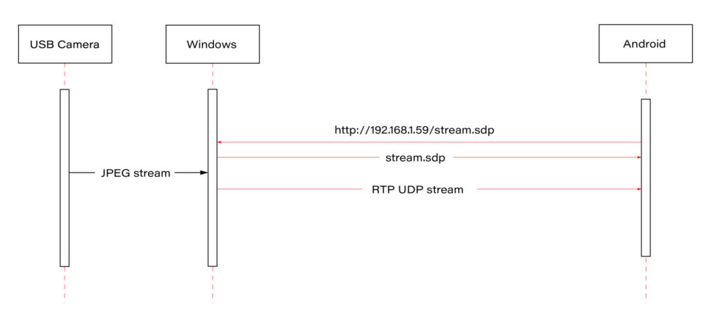
Our approach involves connecting a USB camera to a Windows laptop and streaming the video using the Real-time Transport Protocol (RTP). By employing the powerful FFmpeg software, the video stream will be broadcast and described in an SDP (Session Description Protocol) file, accessible via an HTTP server. On the Android side, we'll utilize the FFmpeg library to receive and decode the video stream, effectively bringing the camera feed into the AAOS 14 environment.
This article provides a step-by-step guide on how we achieved this integration of the EVS network camera, offering insights and practical instructions for those looking to implement a similar solution. The following diagram provides an overview of the entire process:
Building FFmpeg Library for Android
To enable RTP camera streaming on Android, the first step is to build the FFmpeg library for the platform. This section describes the process in detail, using the ffmpeg-android-maker project. Follow these steps to successfully build and integrate the FFmpeg library with the Android EVS (Exterior View System) Driver.
Step 1: Install Android SDK
First, install the Android SDK. For Ubuntu/Debian systems, you can use the following commands:
sudo apt update && sudo apt install android-sdk
The SDK should be installed in /usr/lib/android-sdk .
Step 2: Install NDK
Download the Android NDK (Native Development Kit) from the official website:
https://developer.android.com/ndk/downloads
After downloading, extract the NDK to your desired location.
Step 3: Build FFmpeg
Clone the ffmpeg-android-maker repository and navigate to its directory:
git clone https://github.com/Javernaut/ffmpeg-android-maker.gitcd ffmpeg-android-maker
Set the environment variables to point to the SDK and NDK:
export ANDROID_SDK_HOME=/usr/lib/android-sdk
export ANDROID_NDK_HOME=/path/to/ndk/
Run the build script:
./ffmpeg-android-maker.sh
This script will download FFmpeg source code and dependencies, and compile FFmpeg for various Android architectures.
Step 4: Copy Library Files to EVS Driver
After the build process is complete, copy the .so library files from build/ffmpeg/ to the EVS Driver directory in your Android project:
cp build/ffmpeg/*.so /path/to/android/project/packages/services/Car/cpp/evs/sampleDriver/aidl/
Step 5: Add Libraries to EVS Driver Build Files
Edit the Android.bp file in the aidl directory to include the prebuilt FFmpeg libraries:
cc_prebuilt_library_shared {
    name: "rtp-libavcodec",
    vendor: true,
    srcs: ["libavcodec.so"],
    strip: {
        none: true,
    },
    check_elf_files: false,
}

cc_prebuilt_library {
    name: "rtp-libavformat",
    vendor: true,
    srcs: ["libavformat.so"],
    strip: {
        none: true,
    },
    check_elf_files: false,
}

cc_prebuilt_library {
    name: "rtp-libavutil",
    vendor: true,
    srcs: ["libavutil.so"],
    strip: {
        none: true,
    },
    check_elf_files: false,
}

cc_prebuilt_library_shared {
    name: "rtp-libswscale",
    vendor: true,
    srcs: ["libswscale.so"],
    strip: {
        none: true,
    },
    check_elf_files: false,
}
Add prebuilt libraries to EVS Driver app:
cc_binary {
    name: "android.hardware.automotive.evs-default",
    defaults: ["android.hardware.graphics.common-ndk_static"],
    vendor: true,
    relative_install_path: "hw",
    srcs: [
        ":libgui_frame_event_aidl",
        "src/*.cpp"
    ],
    shared_libs: [
        "rtp-libavcodec",
       	"rtp-libavformat",
       	"rtp-libavutil",
       	"rtp-libswscale",
        "android.hardware.graphics.bufferqueue@1.0",
        "android.hardware.graphics.bufferqueue@2.0",
        android.hidl.token@1.0-utils,

....]
}
By following these steps, you will have successfully built the FFmpeg library for Android and integrated it into the EVS Driver.
EVS Driver RTP Camera Implementation
In this chapter, we will demonstrate how to quickly implement RTP support for the EVS (Exterior View System) driver in Android AAOS 14. This implementation is for demonstration purposes only. For production use, the implementation should be optimized, adapted to specific requirements, and all possible configurations and edge cases should be thoroughly tested. Here, we will focus solely on displaying the video stream from RTP.
The main files responsible for capturing and decoding video from USB cameras are implemented in the EvsV4lCamera and VideoCapture classes. To handle RTP, we will copy these classes and rename them to EvsRTPCamera and RTPCapture . RTP handling will be implemented in RTPCapture . We need to implement four main functions:
bool open(const char* deviceName, const int32_t width = 0, const int32_t height = 0);
void close();
bool startStream(std::function<void(RTPCapture*, imageBuffer*, void*)> callback = nullptr);
void stopStream();
We will use the official example from the FFmpeg library, https://github.com/FFmpeg/FFmpeg/blob/master/doc/examples/demux_decode.c, which decodes the specified video stream into RGBA buffers. After adapting the example, the RTPCapture.cpp file will look like this:
#include "RTPCapture.h"
#include <android-base/logging.h>

#include <errno.h>
#include <error.h>
#include <fcntl.h>
#include <memory.h>
#include <stdio.h>
#include <stdlib.h>
#include <sys/ioctl.h>
#include <sys/mman.h>
#include <unistd.h>

#include <cassert>
#include <iomanip>
#include <stdio.h>
#include <stdlib.h>
#include <iostream>
#include <fstream>
#include <sstream>

static AVFormatContext *fmt_ctx = NULL;
static AVCodecContext *video_dec_ctx = NULL, *audio_dec_ctx;
static int width, height;
static enum AVPixelFormat pix_fmt;

static enum AVPixelFormat out_pix_fmt = AV_PIX_FMT_RGBA;

static AVStream *video_stream = NULL, *audio_stream = NULL;
static struct SwsContext *resize;
static const char *src_filename = NULL;

static uint8_t *video_dst_data[4] = {NULL};
static int video_dst_linesize[4];
static int video_dst_bufsize;

static int video_stream_idx = -1, audio_stream_idx = -1;
static AVFrame *frame = NULL;
static AVFrame *frame2 = NULL;
static AVPacket *pkt = NULL;
static int video_frame_count = 0;

int RTPCapture::output_video_frame(AVFrame *frame)
{
    LOG(INFO) << "Video_frame: " << video_frame_count++
              << " ,scale height: " << sws_scale(resize, frame->data, frame->linesize, 0, height, video_dst_data, video_dst_linesize);
if (mCallback) {
imageBuffer buf;
        buf.index = video_frame_count;
        buf.length = video_dst_bufsize;
        mCallback(this, &buf, video_dst_data[0]);
    }

    return 0;
}

int RTPCapture::decode_packet(AVCodecContext *dec, const AVPacket *pkt)
{
    int ret = 0;

    ret = avcodec_send_packet(dec, pkt);
    if (ret < 0) {
        return ret;
    }

    // get all the available frames from the decoder
    while (ret >= 0) {
        ret = avcodec_receive_frame(dec, frame);
        if (ret < 0) {
            if (ret == AVERROR_EOF || ret == AVERROR(EAGAIN))
            {
                return 0;
            }
            return ret;
        }

        // write the frame data to output file
        if (dec->codec->type == AVMEDIA_TYPE_VIDEO) {
            ret = output_video_frame(frame);
        }

        av_frame_unref(frame);
        if (ret < 0)
            return ret;
    }

    return 0;
}

int RTPCapture::open_codec_context(int *stream_idx,
                              AVCodecContext **dec_ctx, AVFormatContext *fmt_ctx, enum AVMediaType type)
{
    int ret, stream_index;
    AVStream *st;
    const AVCodec *dec = NULL;

    ret = av_find_best_stream(fmt_ctx, type, -1, -1, NULL, 0);
    if (ret < 0) {
        fprintf(stderr, "Could not find %s stream in input file '%s'\n",
                av_get_media_type_string(type), src_filename);
        return ret;
    } else {
        stream_index = ret;
        st = fmt_ctx->streams[stream_index];

        /* find decoder for the stream */
        dec = avcodec_find_decoder(st->codecpar->codec_id);
        if (!dec) {
            fprintf(stderr, "Failed to find %s codec\n",
                    av_get_media_type_string(type));
            return AVERROR(EINVAL);
        }

        /* Allocate a codec context for the decoder */
        *dec_ctx = avcodec_alloc_context3(dec);
        if (!*dec_ctx) {
            fprintf(stderr, "Failed to allocate the %s codec context\n",
                    av_get_media_type_string(type));
            return AVERROR(ENOMEM);
        }

        /* Copy codec parameters from input stream to output codec context */
        if ((ret = avcodec_parameters_to_context(*dec_ctx, st->codecpar)) < 0) {
            fprintf(stderr, "Failed to copy %s codec parameters to decoder context\n",
                    av_get_media_type_string(type));
            return ret;
        }

        av_opt_set((*dec_ctx)->priv_data, "preset", "ultrafast", 0);
        av_opt_set((*dec_ctx)->priv_data, "tune", "zerolatency", 0);

        /* Init the decoders */
        if ((ret = avcodec_open2(*dec_ctx, dec, NULL)) < 0) {
            fprintf(stderr, "Failed to open %s codec\n",
                    av_get_media_type_string(type));
            return ret;
        }
        *stream_idx = stream_index;
    }

    return 0;
}

bool RTPCapture::open(const char* /*deviceName*/, const int32_t /*width*/, const int32_t /*height*/) {
    LOG(INFO) << "RTPCapture::open";

    int ret = 0;
    avformat_network_init();

    mFormat = V4L2_PIX_FMT_YUV420;
    mWidth = 1920;
    mHeight = 1080;
    mStride = 0;

    /* open input file, and allocate format context */
    if (avformat_open_input(&fmt_ctx, "http://192.168.1.59/stream.sdp", NULL, NULL) < 0) {
        LOG(ERROR) << "Could not open network stream";
        return false;
    }
    LOG(INFO) << "Input opened";

    isOpened = true;

    /* retrieve stream information */
    if (avformat_find_stream_info(fmt_ctx, NULL) < 0) {
        LOG(ERROR) << "Could not find stream information";
        return false;
    }
    LOG(INFO) << "Stream info found";

    if (open_codec_context(&video_stream_idx, &video_dec_ctx, fmt_ctx, AVMEDIA_TYPE_VIDEO) >= 0) {
        video_stream = fmt_ctx->streams[video_stream_idx];

        /* allocate image where the decoded image will be put */
        width = video_dec_ctx->width;
        height = video_dec_ctx->height;
        pix_fmt = video_dec_ctx->sw_pix_fmt;

        resize = sws_getContext(width, height, AV_PIX_FMT_YUVJ422P,
                                width, height, out_pix_fmt, SWS_BICUBIC, NULL, NULL, NULL);

        LOG(ERROR) << "RTPCapture::open pix_fmt: " << video_dec_ctx->pix_fmt
                   << ", sw_pix_fmt: " << video_dec_ctx->sw_pix_fmt
                   << ", my_fmt: " << pix_fmt;

        ret = av_image_alloc(video_dst_data, video_dst_linesize,
                             width, height, out_pix_fmt, 1);

        if (ret < 0) {
            LOG(ERROR) << "Could not allocate raw video buffer";
            return false;
        }
        video_dst_bufsize = ret;
    }

    av_dump_format(fmt_ctx, 0, src_filename, 0);

    if (!audio_stream && !video_stream) {
        LOG(ERROR) << "Could not find audio or video stream in the input, aborting";
        ret = 1;
        return false;
    }

    frame = av_frame_alloc();
    if (!frame) {
        LOG(ERROR) << "Could not allocate frame";
        ret = AVERROR(ENOMEM);
        return false;
    }
    frame2 = av_frame_alloc();

    pkt = av_packet_alloc();
    if (!pkt) {
        LOG(ERROR) << "Could not allocate packet";
        ret = AVERROR(ENOMEM);
        return false;
    }

    return true;
}

void RTPCapture::close() {
    LOG(DEBUG) << __FUNCTION__;
}

bool RTPCapture::startStream(std::function<void(RTPCapture*, imageBuffer*, void*)> callback) {
    LOG(INFO) << "startStream";
    if(!isOpen()) {
        LOG(ERROR) << "startStream failed. Stream not opened";
        return false;
    }

    stop_thread_1 = false;
    mCallback = callback;
    mCaptureThread = std::thread([this]() { collectFrames(); });

    return true;
}

void RTPCapture::stopStream() {
    LOG(INFO) << "stopStream";
    stop_thread_1 = true;
    mCaptureThread.join();
    mCallback = nullptr;
}

bool RTPCapture::returnFrame(int i) {
    LOG(INFO) << "returnFrame" << i;
    return true;
}

void RTPCapture::collectFrames() {
    int ret = 0;

    LOG(INFO) << "Reading frames";
    /* read frames from the file */
    while (av_read_frame(fmt_ctx, pkt) >= 0) {
        if (stop_thread_1) {
            return;
        }

        if (pkt->stream_index == video_stream_idx) {
            ret = decode_packet(video_dec_ctx, pkt);
        }
        av_packet_unref(pkt);
        if (ret < 0)
            break;
    }
}

int RTPCapture::setParameter(v4l2_control&) {
    LOG(INFO) << "RTPCapture::setParameter";
    return 0;
}

int RTPCapture::getParameter(v4l2_control&) {
    LOG(INFO) << "RTPCapture::getParameter";
    return 0;
}

std::set<uint32_t> RTPCapture::enumerateCameraControls() {
    LOG(INFO) << "RTPCapture::enumerateCameraControls";
    std::set<uint32_t> ctrlIDs;
    return std::move(ctrlIDs);
}

void* RTPCapture::getLatestData() {
    LOG(INFO) << "RTPCapture::getLatestData";
    return nullptr;
}

bool RTPCapture::isFrameReady() {
    LOG(INFO) << "RTPCapture::isFrameReady";
    return true;
}

void RTPCapture::markFrameConsumed(int i) {
    LOG(INFO) << "RTPCapture::markFrameConsumed frame: " << i;
}

bool RTPCapture::isOpen() {
    LOG(INFO) << "RTPCapture::isOpen";
    return isOpened;
}
Next, we need to modify EvsRTPCamera to use our RTPCapture class instead of VideoCapture . In EvsRTPCamera.h , add:
#include "RTPCapture.h"
And replace:
VideoCapture mVideo = {};
with:
RTPCapture mVideo = {};
In EvsRTPCamera.cpp , we also need to make changes. In the forwardFrame(imageBuffer* pV4lBuff, void* pData) function, replace:
mFillBufferFromVideo(bufferDesc, (uint8_t*)targetPixels, pData, mVideo.getStride());
with:
memcpy(targetPixels, pData, pV4lBuff->length);
This is because the VideoCapture class provides a buffer from the camera in various YUYV pixel formats. The mFillBufferFromVideo function is responsible for converting the pixel format to RGBA. In our case, RTPCapture already provides an RGBA buffer. This is done in the
int RTPCapture::output_video_frame(AVFrame *frame) function using sws_scale from the FFmpeg library.
Now we need to ensure that our RTP camera is recognized by the system. The EvsEnumerator class and its enumerateCameras function are responsible for detecting cameras. This function adds all video files from the /dev/ directory.
To add our RTP camera, we will append the following code at the end of the enumerateCameras function:
if (addCaptureDevice("rtp1")) {
    ++captureCount;
}
This will add a camera with the ID "rtp1" to the list of detected cameras, making it visible to the system.
The final step is to modify the EvsEnumerator: :openCamera function to direct the camera with the ID "rtp1" to the RTP implementation. Normally, when opening a USB camera, an instance of the EvsV4lCamera class is created:
pActiveCamera = EvsV4lCamera::Create(id.data());
In our example, we will hardcode the ID check and create the appropriate object:
if (id == "rtp1") {
    pActiveCamera = EvsRTPCamera::Create(id.data());
} else {
    pActiveCamera = EvsV4lCamera::Create(id.data());
}
With this implementation, our camera should start working. Now we need to build the EVS Driver application and push it to the device along with the FFmpeg libraries:
mmma packages/services/Car/cpp/evs/sampleDriver/
adb push out/target/product/rpi4/vendor/bin/hw/android.hardware.automotive.evs-default /vendor/bin/hw/
Launching the RTP Camera
To stream video from your camera, you need to install FFmpeg ( https://www.ffmpeg.org/download.html#build-windows ) and an HTTP server on the computer that will be streaming the video.
Start FFmpeg (example on Windows):
ffmpeg -f dshow -video_size 1280x720 -i video="USB Camera" -c copy -f rtp rtp://192.168.1.53:8554
where:
- -video_size is video resolution
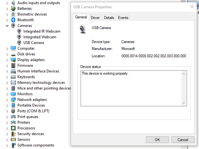
- "USB Camera" is the name of the camera as it appears in the Device Manager
- "-c copy" means that individual frames from the camera (in JPEG format) will be copied to the RTP stream without changes. Otherwise, FFmpeg would need to decode and re-encode the image, introducing unnecessary delays.
- "rtp://192.168.1.53:8554": 192.168.1.53 is the IP address of our Android device. You should adjust this accordingly. Port 8554 can be left as the default.
After starting FFmpeg, you should see output similar to this on the console:
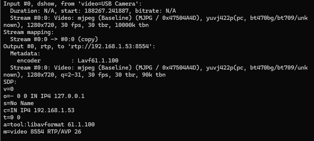
Here, we see the input, output, and SDP sections. In the input section, the codec is JPEG, which is what we need. The pixel format is yuvj422p, with a resolution of 1920x1080 at 30 fps. The stream parameters in the output section should match.
Next, save the SDP section to a file named stream.sdp on the HTTP server. Our EVS Driver application needs to fetch this file, which describes the stream.
In our example, the Android device should access this file at: http://192.168.1.59/stream.sdp
The exact content of the file should be:
v=0
o=- 0 0 IN IP4 127.0.0.1
s=No Name
c=IN IP4 192.168.1.53
t=0 0
a=tool:libavformat 61.1.100
m=video 8554 RTP/AVP 26
Now, restart the EVS Driver application on the Android device:
killall android.hardware.automotive.evs-default
Then, configure the EVS app to use the camera "rtp1". For detailed instructions on how to configure and launch the EVS (Exterior View System), refer to the article "Android AAOS 14 - Surround View Parking Camera: How to Configure and Launch EVS (Exterior View System)".
Performance Testing
In this chapter, we will measure and compare the latency of the video stream from a camera connected via USB and RTP.
How Did We Measure Latency?
- Setup Timer: Displayed a timer on the computer screen showing time with millisecond precision.
- Camera Capture: Pointed the EVS camera at this screen so that the timer was also visible on the Android device screen.
- Snapshot Comparison: Took photos of both screens simultaneously. The time displayed on the Android device was delayed compared to the computer screen. The difference in time between the computer and the Android device represents the camera's latency.
This latency is composed of several factors:
- Camera Latency: The time the camera takes to capture the image from the sensor and encode it into the appropriate format.
- Transmission Time: The time taken to transmit the data via USB or RTP.
- Decoding and Display: The time to decode the video stream and display the image on the screen.
Latency Comparison
Below are the photos showing the latency:
USB Camera
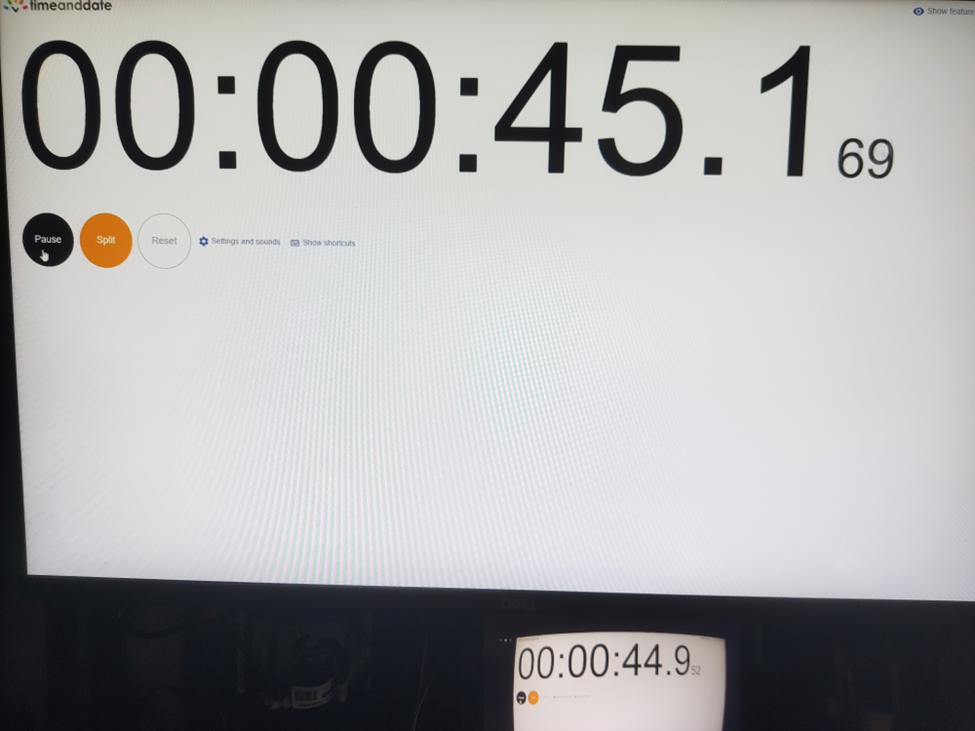
RTP Camera
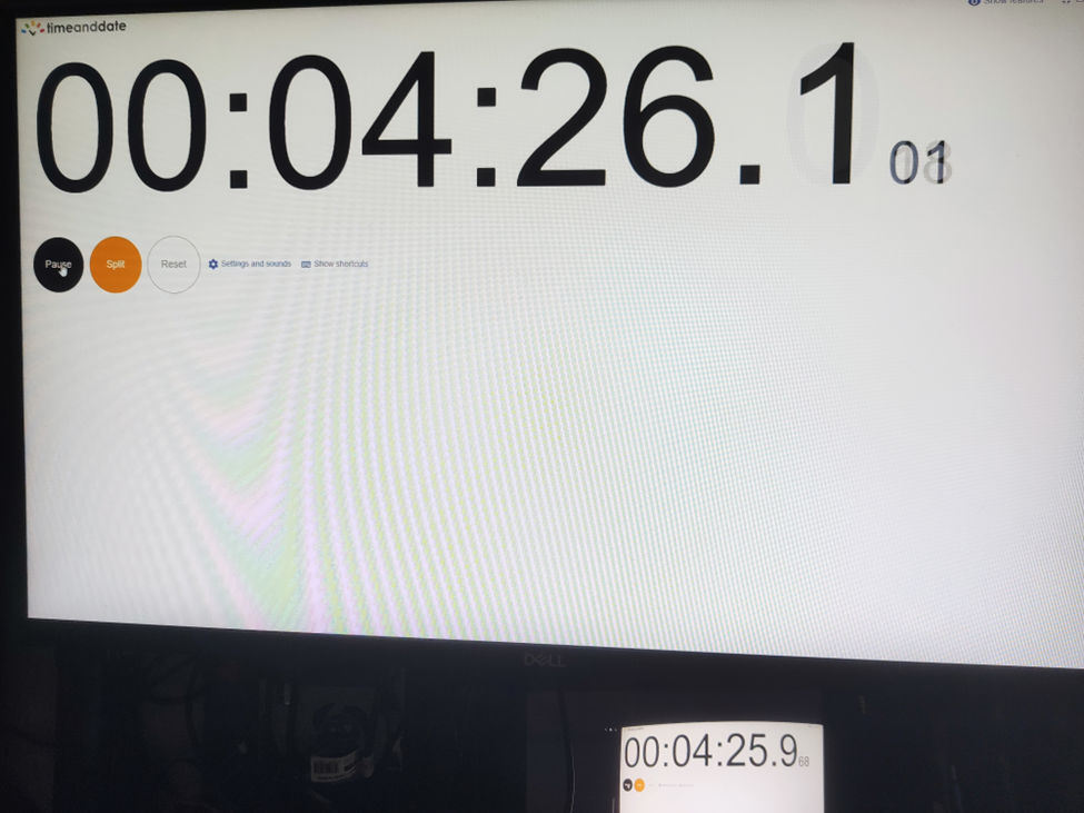
From these measurements, we found that the average latency for a camera connected via USB to the Android device is 200ms , while the latency for the camera connected via RTP is 150ms . This result is quite surprising.
The reasons behind these results are:
- The EVS implementation on Android captures video from the USB camera in YUV and similar formats, whereas FFmpeg streams RTP video in JPEG format.
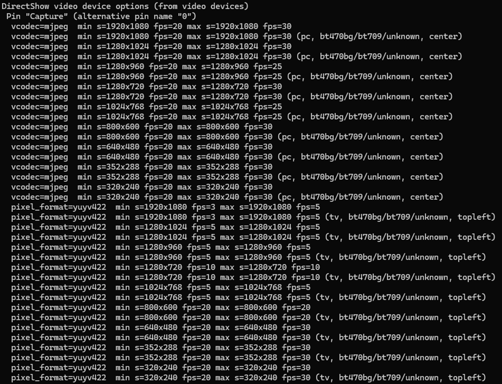
- The USB camera used has a higher latency in generating YUV images compared to JPEG. Additionally, the frame rate is much lower. For a resolution of 1280x720, the YUV format only supports 10 fps, whereas JPEG supports the full 30 fps.
All camera modes can be checked using the command:
ffmpeg -f dshow -list_options true -i video="USB Camera"
Conclusion
This article has taken you through the comprehensive process of integrating an RTP camera into the Android EVS (Exterior View System) framework, highlighting the detailed steps involved in both the implementation and the performance evaluation.
We began our journey by developing new classes, EvsRTPCamera and RTPCapture , which were specifically designed to handle RTP streams using FFmpeg. This adaptation allowed us to process and stream real-time video effectively. To ensure our system recognized the RTP camera, we made critical adjustments to the EvsEnumerator class. By customizing the enumerateCameras and openCamera functions, we ensured that our RTP camera was correctly instantiated and recognized by the system.
Next, we focused on building and deploying the EVS Driver application, including the necessary FFmpeg libraries, to our target Android device. This step was crucial for validating our implementation in a real-world environment. We also conducted a detailed performance evaluation to measure and compare the latency of video feeds from USB and RTP cameras. Using a timer displayed on a computer screen, we captured the timer with the EVS camera and compared the time shown on both the computer and Android screens. This method allowed us to accurately determine the latency introduced by each camera setup.
Our performance tests revealed that the RTP camera had an average latency of 150ms, while the USB camera had a latency of 200ms. This result was unexpected but highly informative. The lower latency of the RTP camera was largely due to the use of the JPEG format, which our particular USB camera handled less efficiently due to its slower YUV processing. This significant finding underscores the RTP camera's suitability for applications requiring real-time video performance, such as automotive surround view parking systems, where quick response times are essential for safety and user experience.
Interested in our services?
Reach out for tailored solutions and expert guidance.