Using Azure DevOps Platform for configurable builds of a multicomponent iOS application

In this article, we share our experience with building CI/CD for a multicomponent multi-language project. The article describes the structure of the pipeline set up and focuses on two important features needed in our project’s automation workflow: pipeline chaining and build variants.
The CI/CD usage is a standard in any application development process . Mobile apps are no exception here.
In our project, we have several iOS applications and libraries. Each application uses several components (frameworks) written in different languages. The components structure is as in the picture below:
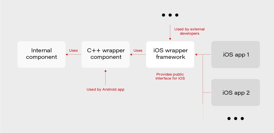
The internal component contains all the core (domain) logic that apps use. The first two components are C/C++ based and are compiled as frameworks. The wrapper framework provides an Objective-C/Swift layer that is necessary for using it in an iOS application. There are several iOS applications that are using the wrapper framework. Additionally, this framework is also used by external developers in their own applications.
The wrapper framework should be built for both x86_64 and arm64 architecture to be used on both a simulator and a real iOS device. Also, we need a debug and release version for each architecture. When it comes to applications each of them may be built for AppStore, internal testing (Ad-Hoc) or TestFlight beta testing.
Without an automated CI/CD system, it would be extremely inefficient to build the whole chain of components manually. As well as to track the status of merges/pull requests for each component. That is to control if the component is still building after the merge. Let’s see how our pipelines are organized.
Using Azure DevOps pipelines
For building CI/CD, we’ve chosen Azure DevOps. We use Azure Pipelines for building our components and Azure Artifacts to host the built components, as well as several external 3rd party libraries.
To check the integrity and track the build status of each component, we have special integration pipelines that are integrated with GitHub. That is, each pull request that is going to be merged to the development branch of a particular component triggers this special integration pipeline.
For regular builds, we have pipelines based on the purpose of each branch type: experimental, feature, bugfix, development, and master.
Since each component depends on another component built on Azure, we should somehow organize the dependency management. That is versioning of the dependent components and their download. Let’s take a look at our approach to dependency management.
Dependency management
Azure provides basic CLI tools to manipulate pipelines. We may use it to download dependencies (inform of Azure artifacts) required to build a particular component. At a minimum, we need to know the version, configuration (debug or release) and architecture (x86_64 or arm64) of a particular dependency. Let’s take a look at the options that Azure CLI gives us:
az artifacts universal download \
--organization "${Organization}" \
--feed "${Feed}" \
--name "${Name}" \
--version "${Version}" \
--path "${DownloadPath}"
The highlighted parameters are the most important for us. The CLI does not provide explicit support of build configuration or architecture. For this purpose, we simply use the name (specified as --name parameter) that has a predefined format:
<component name>-<configuration>-<architecture>
This makes it possible to have components of the same version with different architecture and build configurations.
The other aspect is how to store info about version, configuration, etc., for each dependency. We’ve decided to use the git config format to store this info. It’s pretty easy to parse using git config and does not require any additional parsing tool. So, each component has its own dependencies.config file. Below is the example file for component dependent on two frameworks:
[framework1]
architecture = "arm64"
configuration = "release"
version = "1.2.3.123"[framework2]
architecture = "arm64"
configuration = "release"
version = "3.2.1.654"
To make it possible to download dependencies as part of the build process, we have a special script that manages dependencies. The script is run as a build phase of the Xcode project of each component. Below are the basic steps the script does.
1. Parse dependencies.config file to get version, architecture, and configuration. The important thing here is that if some info is omitted (e.g. we may not specify build configuration in dependencies.config file) script will use the one the dependent component is being built with. That is, when we build the current component for the simulator script will download dependencies of simulator architecture.
2. Form artifact’s name and version and forward them to az artifacts universal download command .
There are two key features of our build infrastructure: pipeline chaining and build variants support. They cover two important cases in our project. Let’s describe how we implemented them.
Chaining pipelines
When a low-level core component is updated, we want to test these changes in the application. For this purpose, we should build the framework dependent on the core component and build the app using this framework. Automation here is extremely useful. Here’s how it looks like with our pipelines.
1. When a low-level component (let’s call it component1 ) is changed on a specific branch (e.g., integration), a special integration pipeline is triggered. When a component is built and an artifact is published, the pipeline starts another pipeline that will build the next dependent component. For this purpose, az pipelines build queue command is used as follows:
az pipelines build queue \
--project "component2" \
--branch "integration" \
--organization "${Organization}" \
--definition-name "${BuildDefinition}" \
--variables \
"config.pipeline.component1Version=${BUILD_BUILDNUMBER}" \
“config.pipeline.component1Architecture=${CurrentArchitecture}" \
"config.pipeline.component1Configuration=${CurrentConfiguration}"
This command starts the pipeline for building component2 (the one dependent on component1 ).
The key part is passing the variables config.pipeline.component1 Version, config.pipeline.component1Architecture and config.pipeline.component1Configuration to the pipeline. These variables define the version, build configuration, and architecture of component1 (the one being built by the current pipeline) that should be used to build component2 . The command overrides the corresponding values from dependencies.config file of component2 . This means that the resulting component2 will use newly built component1 dependency instead of the one defined by dependencies.config file.
2. When component2 is built, it uses the same approach to launch the next pipeline for building a subsequent component.
3. When all the components in the chain required by the app are ready, the integration pipeline building the app is launched. As a part of its build process, the app is sent to TestFlight.
So, simply pushing changes of the lowest level component to the integration branch gives you a ready-to-test app on TestFlight.
Build variants
Some external developers that use the wrapper iOS framework may need additional features that should not be available in regular public API intended for other developers. This brings us to the need of having different variants of the same component. Such variants may be distinct in different features, or in behavior of the same features.
Additional methods or classes may be provided as a specific or experimental API in a wrapper framework for iOS. The other use case is to have behavior different than the default one for regular (official) public API in the wrapper framework. For instance, a method that writes an image file to a specified directory in some cases may be required to also write additional files along with the image (e.g., file with image processing settings or metadata).
Going further, an implementation may be changed not only in the iOS framework itself but also in its dependencies. As described previously, core logic is implemented in a separate component and iOS framework is dependent on. So, when some code behavior change is required by a particular build variant, most likely it will also be done in the internal component.
Let’s see how to better implement build variants. The proper understanding of use cases and potential extension capabilities are crucial for choosing the correct solution.
The first important thing is that in our project different build variants have few changes in API compared to each other. Usually, a build variant contains a couple of additional methods or classes. Most part of the code is the same for all variants. Inside implementation, there also may be some distinctions based on the concrete variant we’re building. So, it would be enough to have some preprocessor definition (active compilation conditions for Swift) indicating which build variant is being built.
The second thing is that the number of build variants is often changed. Some may be removed, (e.g., when an experimental API becomes generally accessible.) On the other hand, when an external developer requests another specific functionality, we need to create a new variant by slightly modifying the standard implementation or exposing some experimental/internal API. This means that we should be able to add or remove build variants fast.
Let’s now describe our implementation based on the specifics given above. There are two parts of the implementation. The first one is at the pipeline level.
Since we may often add/remove our build variants, creating a pipeline for each build variant is obviously not a good idea. Instead, we add a special variable config.pipeline.buildVariant in the pipeline’s Variables to each pipeline that is supposed to be used for building different variants. The variable should be added to pipelines of all the components the resulting iOS framework depends on because a specific feature often requires code changes, not only in the iOS framework itself but also in its dependencies. Pipeline implementation then will use this variable e.g., for downloading specific dependencies required by a particular variant, tagging build to indicate the variant, and, of course, providing the corresponding build setting to Xcode build command.
The second part is a usage of the build variant setting provided by the pipeline inside the Xcode project. Using Xcode build settings we’re adding a compile-time constant (preprocessor definition for Objective C/C++ code and compilation conditions for Swift) that reflect the selected build variant. It is used to control which functionality to compile. This build settings may also be used to choose to build variant-specific resources to be embedded into the framework.
When chaining pipelines we just pass the variable to next pipeline:
az pipelines build queue \
--project "component2" \
--branch "integration" \
--organization "${Organization}" \
--definition-name "${BuildDefinition}" \
--variables \
"config.pipeline.component1Version=${BUILD_BUILDNUMBER}" \
"config.pipeline.component1Architecture=${CurrentArchitecture}" \
"config.pipeline.component1Configuration=${CurrentConfiguration}" \
“config.pipeline.buildVariant=${CONFIG_PIPELINE_BUILDVARIANT}"
Summary
In this article, we’ve described our approach to multi-component app CI/CD infrastructure based on Azure . We’ve focused on two important features of our build infrastructure: chaining component builds and building different variants of the same component. It’s worth mentioning that the described solution is not the only correct one. It's rather the most optimal that fits our needs. You may experiment and try different approaches utilizing a flexible developed pipeline system that Azure provides.

Grape Up guides enterprises on their data-driven transformation journey
Ready to ship? Let's talk.
Check related articles
Read our blog and stay informed about the industry's latest trends and solutions.
How to build hypermedia API with Spring HATEOAS
Have you ever considered the quality of your REST API? Do you know that there are several levels of REST API? Have you ever heard the term HATEOAS? Or maybe you wonder how to implement it in Java? In this article, we answer these questions with the main emphasis on the HATEOAS concept and the implementation of that concept with the Spring HATEOAS project.
Learn more about services provided by Grape Up
You are at Grape Up blog, where our experts share their expertise gathered in projects delivered for top enterprises. See how we work.
Enabling the automotive industry to build software-defined vehicles
Empowering insurers to create insurance telematics platforms
Providing AI & advanced analytics consulting
What is HATEOAS?
H ypermedia A s T he E ngine O f A pplication S tate - is one of the constraints of the REST architecture. Neither REST nor HATEOAS is any requirement or specification. How you implement it depends only on you. At this point, you may ask yourself - how RESTful your API is without using HATEOAS? This question is answered by the REST maturity model presented by Leonard Richardson. This model consists of four levels, as set out below:
- Level 0
The API implementation uses the HTTP protocol but does not utilize its full capabilities. Additionally, unique addresses for resources are not provided. - Level 1
We have a unique identifier for the resource, but each action on the resource has its own URL. - Level 2
We use HTTP methods instead of verbs describing actions, e.g., DELETE method instead of URL .../delete - Level 3
The term HATEOAS has been introduced. Simply speaking, it introduces hypermedia to resources. That allows you to place links in the response informing about possible actions, thereby adding the possibility to navigate through API.
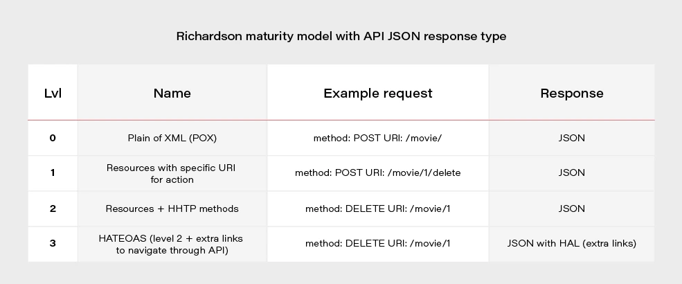
Most projects these days are written using level 2. If we would like to go for the perfect RESTful API, we should consider HATEOAS.
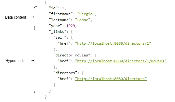
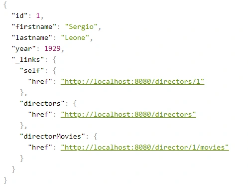
Above, we have an example of a response from the server in the form of JSON+HAL. Such a resource consists of two parts: our data and links to actions that are possible to be performed on a given resource.
Spring HATEOAS 1.x.x
You may be asking yourself how to implement HATEOAS in Java? You can write your solution, but why reinvent the wheel? The right tool for this seems to be the Spring Hateoas project. It is a long-standing solution on the market because its origins date back to 2012, but in 2019 we had a version 1.0 release. Of course, this version introduced a few changes compared to 0.x. They will be discussed at the end of the article after presenting some examples of using this library so that you better understand what the differences between the two versions are. Let’s discuss the possibilities of the library based on a simple API that returns us a list of movies and related directors. Our domain looks like this:
@Entity
public class Movie {
@Id
@GeneratedValue
private Long id;
private String title;
private int year;
private Rating rating;
@ManyToOne
private Director director;
}
@Entity
public class Director {
@Id
@GeneratedValue
@Getter
private Long id;
@Getter
private String firstname;
@Getter
private String lastname;
@Getter
private int year;
@OneToMany(mappedBy = "director")
private Set<Movie> movies;
}
We can approach the implementation of HATEOAS in several ways. Three methods represented here are ranked from least to most recommended.
But first, we need to add some dependencies to our Spring Boot project:
<dependency>
<groupId>org.springframework.boot</groupId>
<artifactId>spring-boot-starter-hateoas</artifactId>
</dependency>
Ok, now we can consider implementation options.
Entity extends RepresentationModel with links directly in Controller class
Firstly, extend our entity models with RepresentationModel.
public class Movie extends RepresentationModel<Movie>
public class Director extends RepresentationModel<Director>
Then, add links to RepresentationModel within each controller. The example below returns all directors from the system. By adding two links to each director - to himself and to the entire collection. A link is also added to the collection. The key elements of this code are two methods with static imports:
-
linkTo() -
methodOn()
@GetMapping("/directors")
public ResponseEntity<CollectionModel<Director>> getAllDirectors() {
List<Director> directors = directorService.getAllDirectors();
directors.forEach(director -> {
director.add(linkTo(methodOn(DirectorController.class).getDirectorById(director.getId())).withSelfRel());
director.add(linkTo(methodOn(DirectorController.class).getDirectorMovies(director.getId())).withRel("directorMovies"));
});
Link allDirectorsLink = linkTo(methodOn(DirectorController.class).getAllDirectors()).withSelfRel());
return ResponseEntity.ok(CollectionModel.of(directors, allDirectorsLink));
}
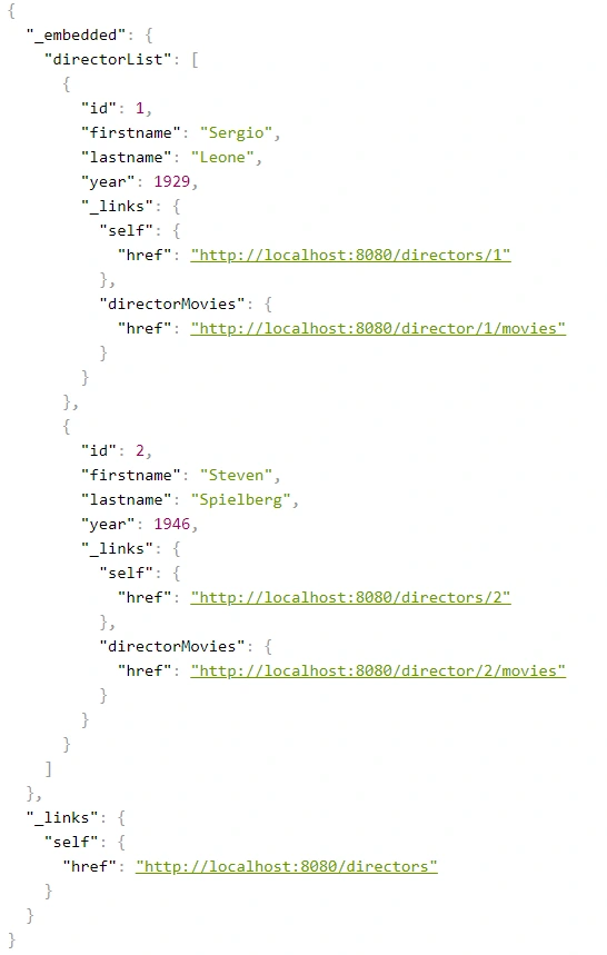
This is the response we get after invoking such controller:
We can get a similar result when requesting a specific resource.
@GetMapping("/directors/{id}")
public ResponseEntity<Director> getDirector(@PathVariable("id") Long id) {
return directorService.getDirectorById(id)
.map(director -> {
director.add(linkTo(methodOn(DirectorController.class).getDirectorById(id)).withSelfRel());
director.add(linkTo(methodOn(DirectorController.class).getDirectorMovies(id)).withRel("directorMovies"));
director.add(linkTo(methodOn((DirectorController.class)).getAllDirectors()).withRel("directors"));
return ResponseEntity.ok(director);
})
.orElse(ResponseEntity.notFound().build());
}
The main advantage of this implementation is simplicity. But making our entity dependent on an external library is not a very good idea. Plus, the code repetition for adding links for a specific resource is immediately noticeable. You can, of course, bring it to some private method, but there is a better way.
Use Assemblers - SimpleRepresentationModelAssembler
And it’s not about assembly language, but about a special kind of class that converts our resource to RepresentationModel.
One of such assemblers is SimpleRepresentationModelAssembler. Its implementation goes as follows:
@Component
public class DirectorAssembler implements SimpleRepresentationModelAssembler<Director> {
@Override
public void addLinks(EntityModel<Director> resource) {
Long directorId = resource.getContent().getId();
resource.add(linkTo(methodOn(DirectorController.class).getDirectorById(directorId)).withSelfRel());
resource.add(linkTo(methodOn(DirectorController.class).getDirectorMovies(directorId)).withRel("directorMovies"));
}
@Override
public void addLinks(CollectionModel<EntityModel<Director>> resources) {
resources.add(linkTo(methodOn(DirectorController.class).getAllDirectors()).withSelfRel());
}
}
In this case, our entity will be wrapped in an EnityModel (this class extends RepresentationModel ) to which the links specified by us in the addLinks() will be added. Here we overwrite two addLinks() methods - one for entire data collections and the other for single resources. Then, as part of the controller, it is enough to call the toModel() or toCollectionModel() method ( addLinks() are template methods here), depending on whether we return a collection or a single representation.
@GetMapping
public ResponseEntity<CollectionModel<EntityModel<Director>>> getAllDirectors() {
return ResponseEntity.ok(directorAssembler.toCollectionModel(directorService.getAllDirectors()));
}
@GetMapping(value = "directors/{id}")
public ResponseEntity<EntityModel<Director>> getDirectorById(@PathVariable("id") Long id) {
return directorService.getDirectorById(id)
.map(director -> {
EntityModel<Director> directorRepresentation = directorAssembler.toModel(director)
.add(linkTo(methodOn(DirectorController.class).getAllDirectors()).withRel("directors"));
return ResponseEntity.ok(directorRepresentation);
})
.orElse(ResponseEntity.notFound().build());
}
The main benefit of using the SimpleRepresentationModelAssembler is the separation of our entity from the RepresentationModel , as well as the separation of the adding link logic from the controller.
The problem arises when we want to add hypermedia to the nested elements of an object. Obtaining the effect, as in the example below, is impossible in a current way.
{
"id": "M0002",
"title": "Once Upon a Time in America",
"year": 1984,
"rating": "R",
"directors": [
{
"id": "D0001",
"firstname": "Sergio",
"lastname": "Leone",
"year": 1929,
"_links": {
"self": {
"href": "http://localhost:8080/directors/D0001"
}
}
}
],
"_links": {
"self": {
"href": "http://localhost:8080/movies/M0002"
}
}
}
Create DTO class with RepresentationModelAssembler
The solution to this problem is to combine the two previous methods, modifying them slightly. In our opinion, RepresentationModelAssembler offers the most possibilities. It removes the restrictions that arose in the case of nested elements for SimpleRepresentationModelAssembler . But it also requires more code from us because we need to prepare DTOs, which are often done anyway. This is the implementation based on RepresentationModelAssembler :
@Component
public class DirectorRepresentationAssembler implements RepresentationModelAssembler<Director, DirectorRepresentation> {
@Override
public DirectorRepresentation toModel(Director entity) {
DirectorRepresentation directorRepresentation = DirectorRepresentation.builder()
.id(entity.getId())
.firstname(entity.getFirstname())
.lastname(entity.getLastname())
.year(entity.getYear())
.build();
directorRepresentation.add(linkTo(methodOn(DirectorController.class).getDirectorById(directorRepresentation.getId())).withSelfRel());
directorRepresentation.add(linkTo(methodOn(DirectorController.class).getDirectorMovies(directorRepresentation.getId())).withRel("directorMovies"));
return directorRepresentation;
}
@Override
public CollectionModel<DirectorRepresentation> toCollectionModel(Iterable<? extends Director> entities) {
CollectionModel<DirectorRepresentation> directorRepresentations = RepresentationModelAssembler.super.toCollectionModel(entities);
directorRepresentations.add(linkTo(methodOn(DirectorController.class).getAllDirectors()).withSelfRel());
return directorRepresentations;
}
}
When it comes to controller methods, they look the same as for SimpleRepresentationModelAssembler , the only difference is that in the ResponseEntity the return type is DTO - DirectorRepresentation .
@GetMapping
public ResponseEntity<CollectionModel<DirectorRepresentation>> getAllDirectors() {
return ResponseEntity.ok(directorRepresentationAssembler.toCollectionModel(directorService.getAllDirectors()));
}
@GetMapping(value = "/{id}")
public ResponseEntity<DirectorRepresentation> getDirectorById(@PathVariable("id") String id) {
return directorService.getDirectorById(id)
.map(director -> {
DirectorRepresentation directorRepresentation = directorRepresentationAssembler.toModel(director)
.add(linkTo(methodOn(DirectorController.class).getAllDirectors()).withRel("directors"));
return ResponseEntity.ok(directorRepresentation);
})
.orElse(ResponseEntity.notFound().build());
}
Here is our DTO model:
@Builder
@Getter
@EqualsAndHashCode(callSuper = false)
@Relation(itemRelation = "director", collectionRelation = "directors")
public class DirectorRepresentation extends RepresentationModel<DirectorRepresentation> {
private final String id;
private final String firstname;
private final String lastname;
private final int year;
}
The @Relation annotation allows you to configure the relationship names to be used in the HAL representation. Without it, the relationship names match the class name and a suffix List for the collection.
By default, JSON+HAL looks like this:
{
"_embedded": {
"directorRepresentationList": [
…
]
},
"_links": {
…
}
}
However, annotation @Relation can change the name of directors :
{
"_embedded": {
"directors": [
…
]
},
"_links": {
…
}
}
Summarizing the HATEOAS concept, it consists of a few pros and cons.
Pros:
- If the client uses it, we can change the API address for our resources without breaking the client.
- Creates good self-documentation, and table of contents of API to the person who has the first contact with our API.
- Can simplify building some conditions on the frontend, e.g., whether the button should be disabled / enabled based on whether the link to corresponding the action exists.
- Less coupling between frontend and backend.
- Just like writing tests imposes on us to stick to the SRP principle in class construction, HATEOAS can keep us in check when designing API.
Cons:
- Additional work needed on implementing non-business functionality.
- Additional network overhead. The size of the transferred data is larger.
- Adding links to some resources can be sometimes complicated and can introduce mess in controllers.
Changes in Spring HATEOAS 1.0
Spring HATEOAS has been available since 2012, but the first release of version 1.0 was in 2019.
The main changes concerned the changes to the package paths and names of some classes, e.g.
Old New ResourceSupport RepresentationModel Resource EntityModel Resources CollectionModel PagedResources PagedModel ResourceAssembler RepresentationModelAssembler
It is worth paying attention to a certain naming convention - the replacement of the word Resource in class names with the word Representation . It occurred because these types do not represent resources but representations, which can be enriched with hypermedia. It is also more in the spirit of REST. We are returning the resource representations, not the resources themselves. In the new version, there is a tendency to move away from constructors in favor of static construction methods - .of() .
It is also worth mentioning that the old version has no equivalent for SimpleRepresentationModelAssembler . On the other hand, the ResourceAssembler interface has only the toResource() method (equivalent - toModel() ) and no equivalent for toCollectionModel() . Such a method is found in RepresentationModelAssembler and is the toModelCollection() method.
The creators of the library have also included a script that migrates old package paths and old class names to the new version. You can check it here .
ASP.NET core CI/CD on Azure Pipelines with Kubernetes and Helm
Due to the high entry threshold, it is not that easy to start a journey with Cloud Native. Developing apps focused on reliability and performance, and meeting high SLAs can be challenging. Fortunately, there are tools like Istio which simplify our lives. In this article, we guide you through the steps needed to create CI/CD with Azure Pipelines for deploying microservices using Helm Charts to Kubernetes. This example is a good starting point for preparing your development process. After this tutorial, you should have some basic ideas about how Cloud Native apps should be developed and deployed .
Technology stack
- .NET Core 3.0 (preview)
- Kubernetes
- Helm
- Istio
- Docker
- Azure DevOps
Prerequisites
You need a Kubernetes cluster, free Azure DevOps account, and a docker registry. Also, it would be useful to have kubectl and gcloud CLI installed on your machine. Regarding the Kubernetes cluster, we will be using Google Kubernetes Engine from Google Cloud Platform, but you can use a different cloud provider based on your preferences. On GCP you can create a free account and create a Kubernetes cluster with Istio enabled ( Enable Istio checkbox). We suggest using a machine with 3 standard nodes.
Connecting the cluster with Azure Pipelines
Once we have the cluster ready, we have to use kubectl to prepare service account which is needed for Azure Pipelines to authenticate. First, authenticate yourself by including necessary settings in kubeconfig. All cloud providers will guide you through this step. Then following commands should be run:
kubectl create serviceaccount azure-pipelines-deploy
kubectl create clusterrolebinding azure-pipelines-deploy --clusterrole=cluster-admin --serviceaccount=default:azure-pipelines-deploy
kubectl get secret $(kubectl get secrets -o custom-columns=":metadata.name" | grep azure-pipelines-deploy-token) -o yaml
We are creating a service account, to which a cluster role is assigned. The cluster-admin role will allow us to use Helm without restrictions. If you are interested, you can read more about RBAC on Kubernetes website . The last command is supposed to retrieve secret yaml , which is needed to define connection - save that output yaml somewhere.
Now, in Azure DevOps, go to Project Settings -> Service Connections and add a new Kubernetes service connection. Choose service account for authentication and paste the yaml copied from command executed in the previous step.
One more thing we need in here is the cluster IP. It should be available at cluster settings page, or it can be retrieved via command line. In the example, for GCP command should be similar to this:
gcloud container clusters describe --format=value(endpoint) --zone
Another service connection we have to define is for docker registry. For the sake of simplicity, we will use the Docker hub, where all you need is just to create an account (if you don’t have one). Then just supply whatever is needed in the form, and we can carry on with the application part.
Preparing an application
One of the things we should take into account while implementing apps in the Cloud is the Twelve-Factor methodology. We are not going to describe them one by one since they are explained good enough here but few of them will be mentioned throughout the article.
For tutorial purposes, we’ve prepared a sample ASP.NET Core Web Application containing a single controller and database context. It also contains simple dockerfile and helm charts. You can clone/fork sample project from here . Firstly, push it to a git repository (we will use Azure DevOps), because we will need it for CI. You can now add a new pipeline, choosing any of the available YAML definitions. In here we will define our build pipeline (CI) which looks like that:
trigger:
- master
pool:
vmImage: 'ubuntu-latest'
variables:
buildConfiguration: 'Release'
steps:
- task: Docker@2
inputs:
containerRegistry: 'dockerRegistry'
repository: '$(dockerRegistry)/$(name)'
command: 'buildAndPush'
Dockerfile: '**/Dockerfile'
- task: PublishBuildArtifacts@1
inputs:
PathtoPublish: '$(Build.SourcesDirectory)/charts'
ArtifactName: 'charts'
publishLocation: 'Container'
Such definition is building a docker image and publishing it into predefined docker registry. There are two custom variables used, which are dockerRegistry (for docker hub replace with your username) and name which is just an image name (exampleApp is our case). The second task is used for publishing artifact with helm chart. These two (docker image & helm chart) will be used for the deployment pipeline.
Helm charts
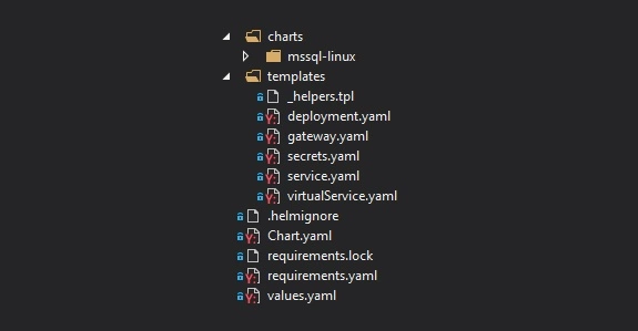
Firstly, take a look at the file structure for our chart. In the main folder, we have Chart.yaml which keeps chart metadata, requirements.yaml with which we can specify dependencies or values.yaml which serves default configuration values. In the templates folder, we can find all Kubernetes objects that will be created along with chart deployment. Then we have nested charts folder, which is a collection of charts added as a dependency in requirements.yaml. All of them will have the same file structure.
Let’s start with a focus on the deployment.yaml - a definition of Deployment controller, which provides declarative updates for Pods and Replica Sets. It is parameterized with helm templates, so you will see a lot of {{ template [...] }} in there. Definition of this Deployment itself is quite default, but we are adding a reference for the secret of SQL Server database password. We are hardcoding ‘-mssql-linux-secret’ part cause at the time of writing this article, helm doesn’t provide a straightforward way to access sub-charts properties.
env:
- name: sa_password
valueFrom:
secretKeyRef:
name: {{ template "exampleapp.name" $root }}-mssql-linux-secret
key: sapassword
As we mentioned previously, we do have SQL Server chart added as a dependency. Definition of that is pretty simple. We have to define the name of the dependency, which will match the folder name in charts subfolder and the version we want to use.
dependencies:
- name: mssql-linux
repository: https://kubernetes-charts.storage.googleapis.com
version: 0.8.0
[...]
For the mssql chart, there is one change that has to be applied in the secret.yaml . Normally, this secret will be created on each deployment ( helm upgrade ), it will generate a new sapassword - which is not what we want. The simplest way to adjust that is by modifying metadata and adding a hook on pre-install. This will guarantee that this secret will be created just once on installing the release.
metadata:
annotations:
"helm.sh/hook": "pre-install"
A deployment pipeline
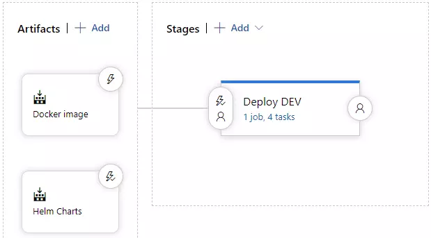
Let’s focus on deployment now. We will be using Helm to install and upgrade everything that will be needed in Kubernetes. Go to the Releases pipelines on the Azure DevOps, where we will configure continuous delivery. You have to add two artifacts, one for docker image and second for charts artifact. It should look like on the image below.
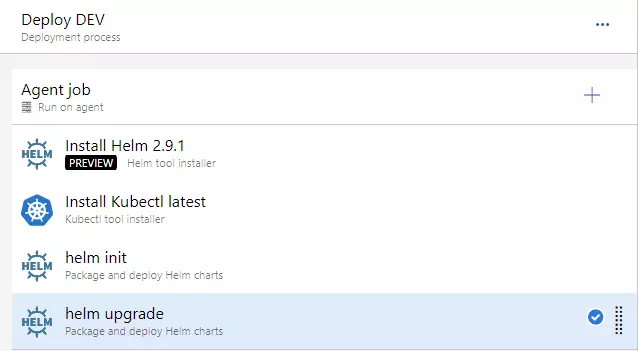
On the stages part, we could add a few more environments, which would get deployed in a similar manner, but to a different cluster. As you can see, this approach guarantees Deploy DEV stage is simply responsible for running a helm upgrade command. Before that, we need to install helm, kubectl and run helm init command.
For the helm upgrade task, we need to adjust a few things.
- set Chart Path, where you can browse into Helm charts artifact (should look like: “$(System.DefaultWorkingDirectory)/Helm charts/charts”)
- paste that “image.tag=$(Build.BuildNumber)” into Set Values
- and check to Install if release not present or add --install ar argument. This will behave as helm install if release won’t exist (i.e. on a clean cluster)
At this point, we should be able to run the deployment application - you can create a release and run deployment. You should see a green output at this point :).
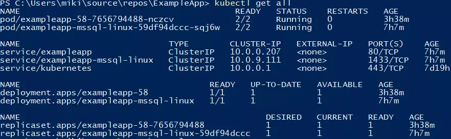
You can verify if the deployment went fine by running a kubectl get all command.
Making use of basic Istio components
Istio is a great tool, which simplifies services management. It is responsible for handling things like load balancing, traffic behavior, metric & logs, and security. Istio is leveraging Kubernetes sidecar containers, which are added to pods of our applications. You will have to enable this feature by applying an appropriate label on the namespace.
kubectl label namespace default istio-injection=enabled
All pods which will be created now will have an additional container, which is called a sidecar container in Kubernetes terms. That’s a useful feature, cause we don’t have to modify our application.
Two objects that we are using from Istio, which are part of the helm chart, are Gateway and VirtualService . For the first one, we will bring Istio definition, because it’s simple and accurate: “Gateway describes a load balancer operating at the edge of the mesh receiving incoming or outgoing HTTP/TCP connections”. That object is attached to the LoadBalancer object - we will use the one created by Istio by default. After the application is deployed, you will be able to access it using LoadBalancer external IP, which you can retrieve with such command:
kubectl get service/istio-ingressgateway -n istio-system
You can retrieve external IP from the output and verify if http://api/examples url works fine.
Summary
In this article, we have created a basic CI/CD which deploys single service into Kubernetes cluster with the help of Helm. Further adjustments can include different types of deployment, publishing tests coverage from CI or adding more services to mesh and leveraging additional Istio features. We hope you were able to complete the tutorial without any issues. Follow our blog for more in-depth articles around these topics that will be posted in the future.
Apache Kafka fundamentals
Nowadays, we have plenty of unique architectural solutions. But all of them have one thing in common – every single decision should be done after a solid understanding of the business case as well as the communication structure in a company. It is strictly connected with famous Conway’s Law:
“Any organization that designs a system (defined broadly) will produce a design whose structure is a copy of the organization's communication structure.”
In this article, we go deeper into the Event-Driven style, and we discover when we should implement such solutions. This is when Kafka comes to play.
The basic definition taken from the Apache Kafka site states that this is an open-source distributed event streaming platform . But what exactly does it mean? We explain the basic concepts of Apache Kafka, how to use the platform, and when we may need it.
Apache Kafka is all about events
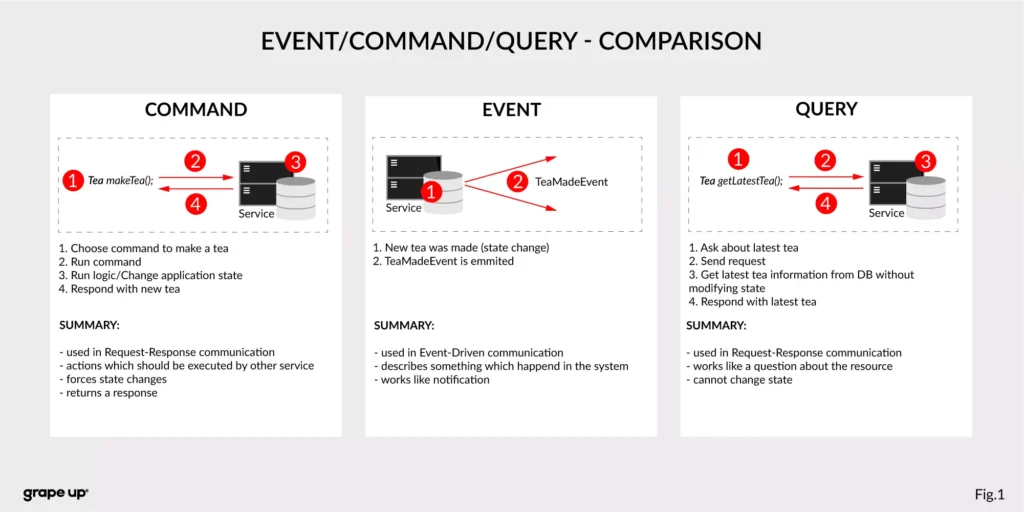
To understand what the event streaming platform is, we need to have a prior understanding of an event itself. There are different ways of how the services can interact with each other – they can use Commands, Events, or Queries. So, what is the difference between them?
- Command – we can call it a message in which we expect something to be done - like in the army when the commander gives an order to soldiers. In computer science, we are making requests to other services to perform some action, which causes a system state change. The crucial part is that they are synchronous, and we expect that something will happen in the future. It is the most common and natural method for communication between services. On the other hand, you do not really know if your expectation will be fulfilled by the service. Sometimes we create commands, and we do not expect any response (it is not needed for the caller.)
- Event – the best definition of an event is a fact. It is a representation of the change which happened in the service (domain). It is essential that there is no expectation of any future action. We can treat an event as a notification of state change. Events are immutable. In other words - it is everything necessary for the business. This is also a single source of truth, so events need to precisely describe what happened in the system.
- Query – in comparison to the others, the query is only returning a response without any modifications in the system state. A good example of how it works can be an SQL query.
Below there is a small summary which compares all the above-mentioned ways of interaction:
Now we know what the event is in comparison to other interaction styles. But what is the advantage of using events? To understand why event-driven solutions are better than synchronous request-response calls, we have to learn a bit about software architecture history.
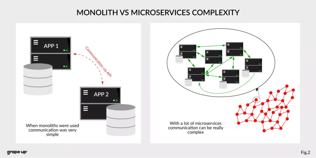
The figure describes a difference between a system that has old monolith architecture and a system with new modern microservice architecture.
The left side of the figure presents an API communication between two monoliths. In this case, communication is straightforward and easy. There is a different problem though such monolith solutions are very complex and hard to maintain.
The question is, what happens if we want to use, instead of two big services, a few thousands of small microservices . How complex will it be? The directed graph on the right side is showing how quickly the number of calls in the system can grow, and with it, the number of shared resources. We can have a situation when we need to use data from one microservice in many places. That produces new challenges regarding communication.
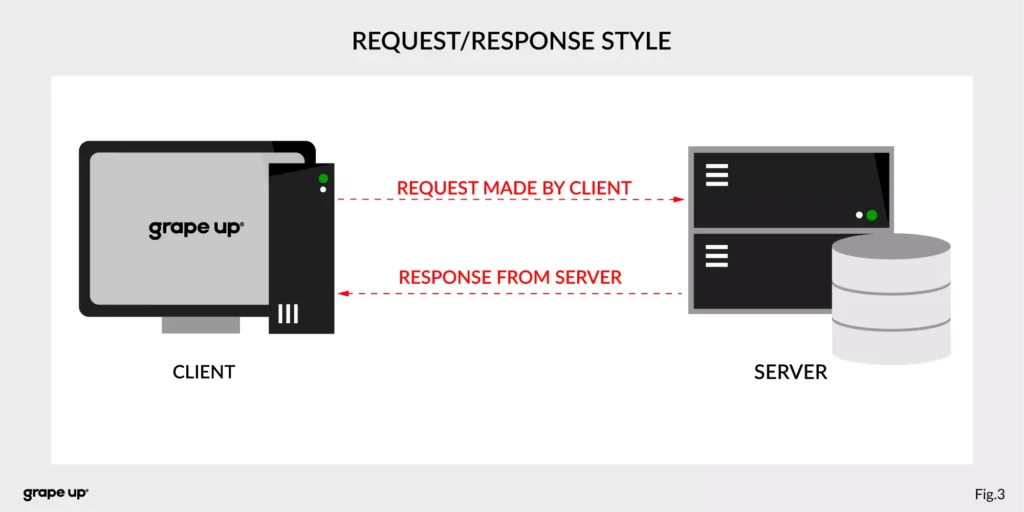
What about communication style?
In both cases, we are using a request-response style of communication (figure below), and we need to know how to use API provided by the server from the caller perspective. There must be some kind of protocol to exchange messages between services.
So how to reduce the complexity and make an integration between services easier? To answer this – look at the figure below.
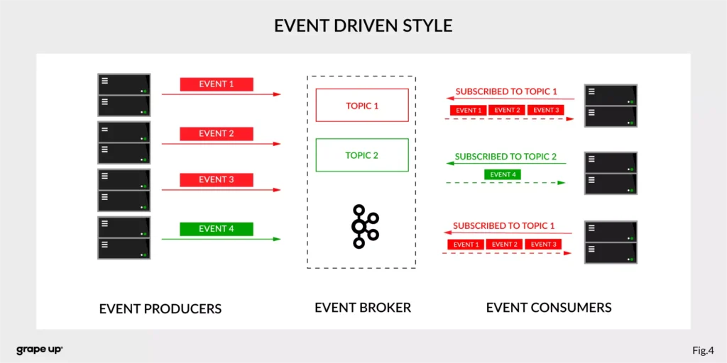
In this case, interactions between event producers and consumers are driven by events only. This pattern supports loose coupling between services, and what is more important for us, the event producer does not need to be aware of the event consumer state. It is the essence of the pattern. From the producer's perspective, we do not need to know who or how to use data from the topic.
Of course, as usual, everything is relative. It is not like the event-driven style is always the best. It depends on the use case. For instance, when operations should be done synchronously, then it is natural to use the request-response style. In situations like user authentication, reporting AB tests, or integration with third-party services, it is better to use a synchronous style. When the loose coupling is a need, then it is better to go with an event-driven approach. In larger systems, we are mixing styles to achieve a business goal.
The name of Kafka has its origins in the word Kafkaesque which means according to the Cambridge dictionary something extremely unpleasant, frightening, and confusing, and similar to situations described in the novels of Franz Kafka.
The communication mess in the modern enterprise was a factor to invent such a tool. To understand why - we need to take a closer look at modern enterprise systems.
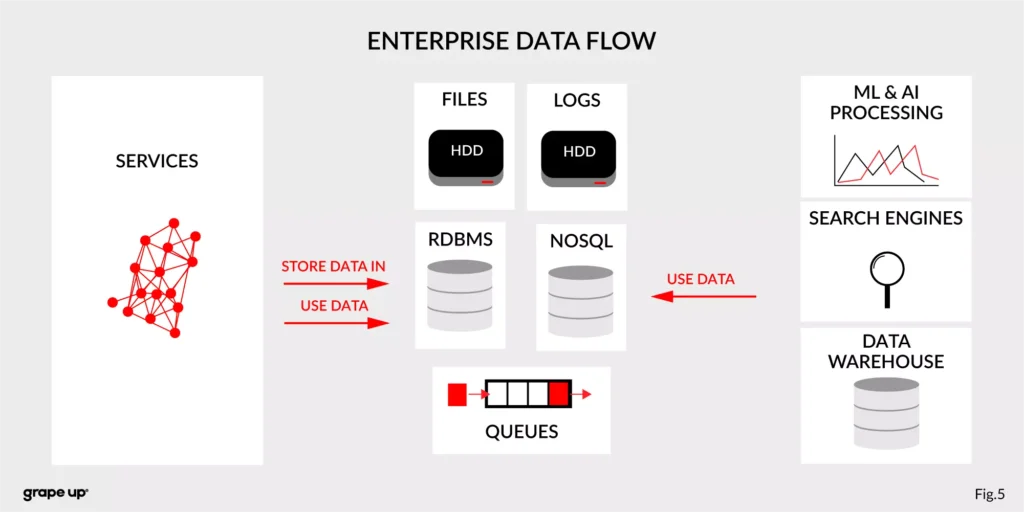
The modern enterprise systems contain more than just services. They usually have a data warehouse, AI and ML analytics, search engines, and much more. The format of data and the place where data is stored are various – sometimes a part of the data is stored in RDBMS, a part in NoSQL, and other in file bucket or transferred via a queue. They can have different formats and extensions like XML, JSON, and so on. Data management is the key to every successful enterprise. That is why we should care about it. Tim O’Reilly once said:
„We are entering a new world in which data may be more important than software.”
In this case, having a good solution for processing crucial data streams across an enterprise is a must to be successful in business. But as we all know, it is not always so easy.
How to tame the beast?
For this complex enterprise data flow scenario, people invented many tools/methods. All to make this enterprise data distribution possible. Unfortunately, as usual, to use them, we have to make some tradeoffs. Here we have a list of them:
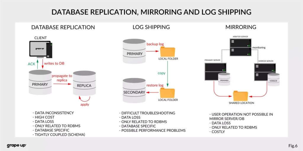
- Database replication, Mirroring, and Log Shipping - used to increase the performance of an application (scaling) and backup/recovery.
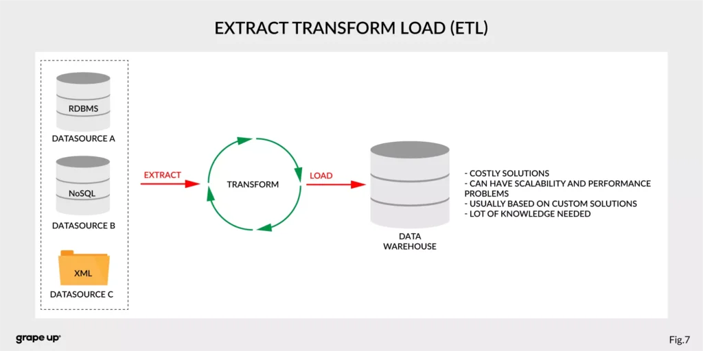
- ETL – Extract, Transform, Load - used to copy data from different sources for analytics/reports.
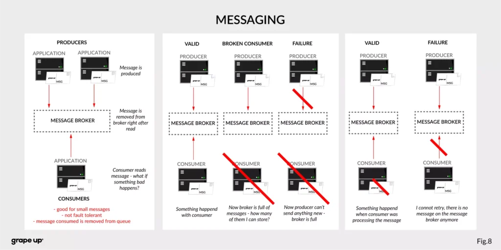
- Messaging systems - provide asynchronous communication between systems.
As you can see, we have a lot of problems that we need to take care of to provide correct data flow across an enterprise organization. That is why Apache Kafka was invented. One more time we have to go to the definition of Apache Kafka. It is called a distributed event streaming platform. Now we know what the event is and how event-driven style looks like. So as you probably can guess, event streaming, in our case, means capturing, storing, manipulating, processing, reacting, and routing event streams in real-time. It is based on three main capabilities – publishing/subscribing, storing, and processing. These three capabilities make this tool very successful.
- Publishing/Subscribing provides an ability to read/write to streams of events and even more – you can continuously import/export data from different sources/systems.
- Storing is also very important here. It solves the abovementioned problems in messaging. You can store streams of events for as long as you want without being afraid that something will be gone.
- Processing allows us to process streams in real-time or use history to process them.
But wait! There is one more word to explain – distributed. Kafka system internally consists of servers and clients. It uses a high-performance TCP Protocol to provide reliable communication between them. Kafka runs as a cluster on one or multiple servers which can be easily deployed in the cloud or on-prem in single or multiple regions. There are also Kafka Connect servers used for integration with other data sources and other Kafka Clusters. Clients that can be implemented in many programming languages have a special role to read/write and process event streams. The whole ecosystem of Kafka is distributed and of course like every distributed system has a lot of challenges regarding node failures, data loss, and coordination.
What are the basic elements of Apache Kafka?
To understand how Apache Kafka works let first explain the basic elements of the Kafka ecosystem.
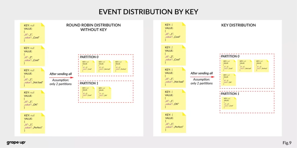
Firstly, we should take a look at the event. It has a key, value, timestamp, and optional metadata headers. A key is used not only for identification, but it is used also for routing and aggregation operations for events with the same key.
As you can see in the figure below - if the message has no key attached, then data is sent using a round-robin algorithm. The situation is different when the event has a key attached. Then the events always go to the partition which holds this key. It makes sense from the performance perspective. We usually use ids to get information about objects, and in that case, it is faster to get it from the same broker than to look for it on many brokers.
The value, as you can guess, stores the essence of the event. It contains information about the business change that happened in the system.
There are different types of events:
- Unkeyed Event – event in which there is no need to use a key. It describes a single fact of what happened in the system. It could be used for metric purposes.
- Entity Event – the most important one. It describes the state of the business object at a given point in time. It must have a unique key, which usually is related to the id of the business object. They are playing the main role in event-driven architectures.
- Keyed Event – an event with a key but not related to any business entity. The key is used for aggregation and partitioning.
Topics –storage for events. The analogy to a folder in a filesystem, where the topic is like a folder that organizes what is inside. An example name of the topic, which keeps all orders events in the e-commerce system can be “ orders” . Unlike in other messaging systems, the events stay on the topic after reading. It makes it very powerful and fault-tolerant. It also solves a problem when the consumer will process something with an error and would like to process it again. Topics can always have zero, single, and multiple producers and subscribers.
They are divided into smaller parts called partitions. A partition can be described as a “commit log”. Messages can be appended to the log and can be read only in the order from the beginning to the end. Partitions are designed to provide redundancy and scalability. The most important fact is that partitions can be hosted on different servers (brokers), and that gives a very powerful way to scale topics horizontally.
Producer – client application responsible for the creation of new events on Kafka Topic. The producer is responsible for choosing the topic partition. By default, as we mentioned earlier round-robin is used when we do not provide any key. There is also a way of creating custom business mapping rules to assign a partition to the message.
Consumer – client application responsible for reading and processing events from Kafka. All events are being read by a consumer in the order in which they were produced. Each consumer also can subscribe to more than one topic. Each message on the partition has a unique integer identifier ( offset ) generated by Apache Kafka which is increased when a new message arrives. It is used by the consumer to know from where to start reading new messages. To sum up the topic, partition and offset are used to precisely localize the message in the Apache Kafka system. Managing an offset is the main responsibility for each consumer.
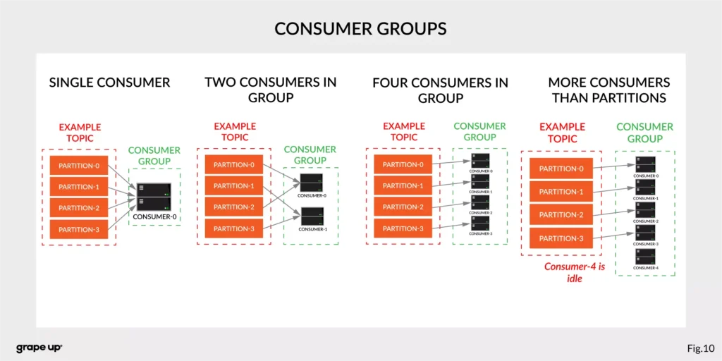
The concept of consumers is easy. But what about the scaling? What if we have many consumers, but we would like to read the message only once? That is why the concept of consumer group was designed. The idea here is when consumer belongs to the same group, it will have some subset of partitions assigned to read a message. That helps to avoid the situation of duplicated reads. In the figure below, there is an example of how we can scale data consumption from the topic. When a consumer is making time-consuming operations, we can connect other consumers to the group, which helps to process faster all new events on the consumer level. We have to be careful though when we have a too-small number of partitions, we would not be able to scale it up. It means if we have more consumers than partitions, they are idle.
But you can ask – what will happen when we add a new consumer to the existing and running group? The process of switching ownership from one consumer to another is called “rebalance.” It is a small break from receiving messages for the whole group. The idea of choosing which partition goes to which consumer is based on the coordinator election problem.
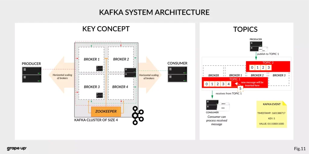
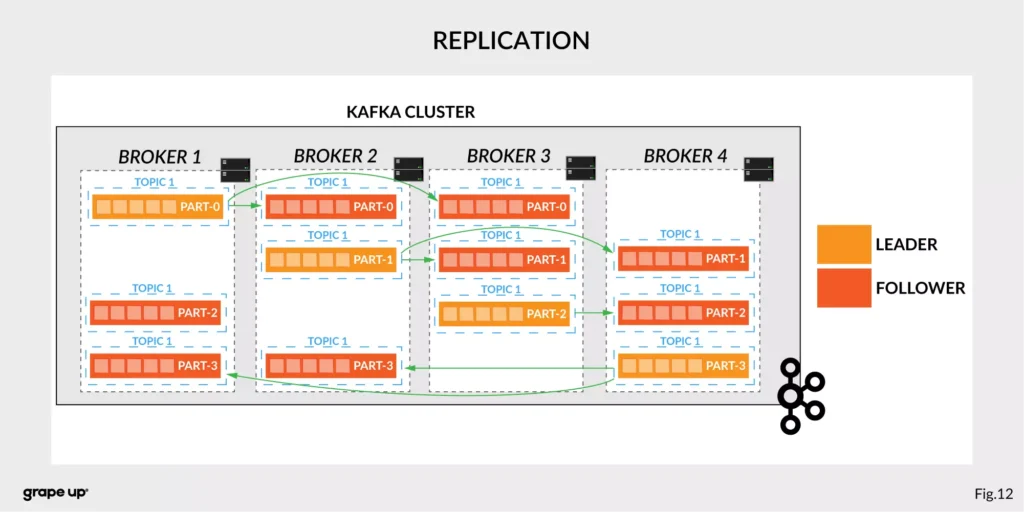
Broker – is responsible for receiving and storing produced events on disk, and it allows consumers to fetch messages by a topic, partition, and offset. Brokers are usually located in many places and joined in a cluster . See the figure below.
Like in every distributed system, when we use brokers we need to have some coordination. Brokers, as you can see, can be run on different servers (also it is possible to run many on a single server). It provides additional complexity. Each broker contains information about partitions that it owns. To be secure, Apache Kafka introduced a dedicated replication for partitions in case of failures or maintenance. The information about how many replicas do we need for a topic can be set for every topic separately. It gives a lot of flexibility. In the figure below, the basic configuration of replication is shown. The replication is based on the leader-follower approach.
Everything is great! We have found all advantages of using Kafka in comparison to more traditional approaches. Now it is time to say something when to use it.
When to use Apache Kafka?
Apache Kafka provides a lot of use cases. It is widely used in many companies, like Uber, Netflix, Activision, Spotify, Slack, Pinterest, Coursera, LinkedIn, etc. We can use it as a:
- Messaging system – it can be a good alternative to the existing messaging systems. It has a lot of flexibility in configuration, better throughput, and low end-to-end latency.
- Website Activity tracking – it was the original use case for Kafka. Activity tracking on the website generates a high volume of data that we have to process. Kafka provides real-time processing for event-streams, which can be sometimes crucial for the business.
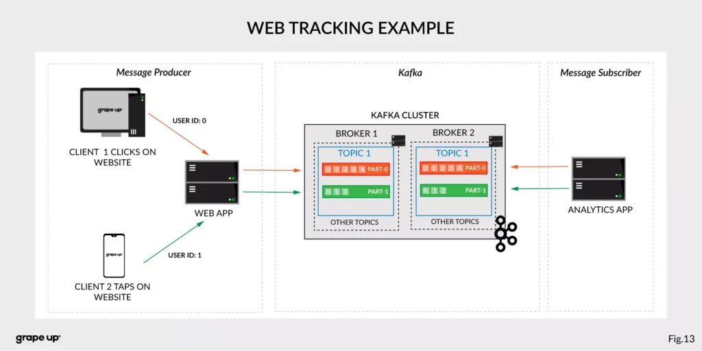
Figure 13 presents a simple use case for web tracking. The web application has a button that generates an event after each click. It is used for real-time analytics. Clients' events that are gathered on TOPIC 1. Partitioning is using user-id so client 1 events (user-id = 0) are stored in partition 0 and client 2 (user-id = 1) are stored in partition 1. The record is appended and offset is incremented on a topic. Now, a subscriber can read a message, and present new data on a dashboard or even use older offset to show some statistics.
- Log aggregation – it can be used as an alternative to existing log aggregation solutions. It gives a cleaner way of organizing logs in form of the event streams and what is more, gives a very easy and flexible way to gather logs from many different sources. Comparing to other tools is very fast, durable, and has low end-to-end latency.
- Stream processing – is a very flexible way of processing data using data pipelines. Many users are aggregating, enriching, and transforming data into new topics. It is a very quick and convenient way to process all data in real-time.
- Event sourcing – is a system design in which immutable events are stored as a single source of truth about the system. A typical use case for event sourcing can be found in bank systems when we are loading the history of transactions. The transaction is represented by an immutable event which contains all data describing what exactly happened in our account.
- Commit log – it can be used as an external commit-log for distributed systems. It has a lot of mechanisms that are useful in this use case (like log-compaction, replication, etc.)
Summary
Apache Kafka is a powerful tool used by leading tech enterprises. It offers a lot of use cases, so if we want to use a reliable and durable tool for our data, we should consider Kafka. It provides a loose coupling between producers and subscribers, making our enterprise architecture clean and open to changes. We hope you enjoyed this basic introduction to Apache Kafka and you will try to dig deeper into how it works after this article.
Looking for guidance on implementing Kafka or other event-driven solutions?
Get in touch with us to discuss how we can help.
Sources:
- kafka.apache.org/intro
- confluent.io/blog/journey-to-event-driven-part-1-why-event-first-thinking-changes-everything/
- hackernoon.com/by-2020-50-of-managed-apis-projected-to-be-event-driven-88f7041ea6d8
- ably.io/blog/the-realtime-api-family/
- confluent.io/blog/changing-face-etl/
- infoq.com/articles/democratizing-stream-processing-kafka-ksql-part2/
- cqrs.nu/Faq
- medium.com/analytics-vidhya/apache-kafka-use-cases-e2e52b892fe1
- confluent.io/blog/transactions-apache-kafka/
- martinfowler.com/articles/201701-event-driven.html
- pluralsight.com/courses/apache-kafka-getting-started#
- jaceklaskowski.gitbooks.io/apache-kafka/content/kafka-brokers.html
Bellemare, Adam. Building event-driven microservices: leveraging distributed large-scale data . O'Reilly Media, 2020.
Narkhede, Neha, et al. Kafka: the Definitive Guide: Real-Time Data and Stream Processing at Scale . O'Reilly Media, 2017.
Stopford, Ben. Designing Event-Driven Systems, Concepts and Patterns for Streaming Services with Apache Kafka , O'Reilly Media, 2018.
Interested in our services?
Reach out for tailored solutions and expert guidance.