Automating your enterprise infrastructure. Part 2: Cloud Infrastructure as code in practice (AWS Cloud Formation example)

Given that you went through Part 1 of the Infrastructure automation guide, and you already know basic Infrastructure as Code and AWS Cloud Formation concepts, we can proceed with getting some hands-on experience!
Learn more about services provided by Grape Up
You are at Grape Up blog, where our experts share their expertise gathered in projects delivered for top enterprises. See how we work.
Enabling the automotive industry to build software-defined vehicles
Empowering insurers to create insurance telematics platforms
Providing AI & advanced analytics consulting
Note that in this article, we’ll build Infrastructure as Code scripts for the infrastructure described by Michal Kapiczynski in the series of mini-articles .
HINT Before we begin:
If you’re building your Cloud Formation scripts from scratch, we highly recommend starting with spinning the infrastructure manually from the AWS console, and later on, use the AWS CLI tool to get a ‘description’ of the resource. The output will show you the parameters and their values that were used to create the resource.
E.g use:
aws ec2 describe-instances
to obtain properties for EC2 instances.
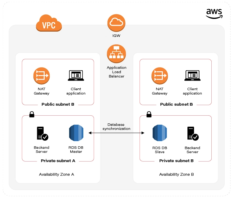
Let's recall what is our target state:
As already mentioned in the first part of the automation guide , we've split the infrastructure setup into two Templates (scripts). Let’s start with the first one, called infra-stack, as it contains Architecture scaffolding resources:
- VPC
- Subnets
- Internet gateway
- Elastic IP
- NAT
- Route Tables
Note: All of the Cloud Formation scripts presented below and even more are publicly accessible in this GitHub repository .
VPC
The backbone - Virtual private cloud, in fact a network that hosts all of our resources. Cloud Formation definition for this one is a simple one. See:
UserManagementVpc:
Type: AWS::EC2::VPC
Properties:
CidrBlock: "10.0.0.0/22"
Tags:
- Key: "Name"
Value: "UserManagementVpc"
Just a few lines of code. The first line defines the Amazon resource name, we’ll use this name later on to reference the VPC. Type specifies whether this is VPC, Subnet, EC2 VM, etc. The Properties section contains a set of configuration key-value pairs fixed for a particular resource. The only required property that we define here is CidrBlock of our VPC. Note the network mask (256.256. 252.0 ). Additionally, we can specify a Name Tag that might help us to quickly find our VPC amid the VPC list in the AWS console.
Subnets
As stated above, we’ll need 4 subnets. Specifically, one public and one private network subnet in Availability Zone A. The same goes for AZ B. Let’s see public subnet A definition:
PubSubnetA:
Type: AWS::EC2::Subnet
Properties:
AvailabilityZone: !Sub '${Region}a'
CidrBlock: 10.0.0.0/24
Tags:
- Key: 'Name'
Value: 'PubSubnetA'
VpcId: !Ref UserManagementVpc
When specifying AvailabilityZone, we can use !Sub function to substitute Region script parameter variable name with the actual value and at the same time, concatenate it with ‘a’ suffix. This is to have an actual AWS Region name. So, e.g. taking the Region default value, the actual value for AvailabilityZone in the figure above is “eu-central-1a“.
Next, we have to specify CidrBock of the subnet. This one is easy, though note that subnet cidr should be ‘within’ VPC cidr block.
Last but not least, VpcId . At the time we write the script, we don’t know the actual VPC identifier, that’s why we have to reference ( !Ref ) VPC by its name ( UserManagementVpc) .
Both of the functions - !Sub and !Ref are so-called intrinsic function references built-in into cloud formation service. More on that here .
We won’t go through the rest of the Subnet definitions, these are basically the same, the only thing that changes is AvailabilityZone suffix and CirdBlock. You can find these definitions in the Github repository .
Internet gateway
This one seems to be a simple one:
IGW:
Type: AWS::EC2::InternetGateway
Properties:
Tags:
- Key: "Name"
Value: "MyIGW"
The only required field is Type. Not so fast though. As we already know IGW should be attached to a specific VPC, but there is no VPC reference here! Here comes the other Resource called VpcGatewayAttachment:
IgwAttachment:
Type: AWS::EC2::VPCGatewayAttachment
Properties:
InternetGatewayId: !Ref IGW
VpcId: !Ref UserManagementVpc
As we clearly see, this one is responsible for the association between IGW and VPC. Same as in Subnet definition, we can reference these by name using !Ref.
Elastic IP
Now, let’s take care of the prerequisites for NAT setup. We ought to set up Elastic IP that NAT can reference later on. We need two of these for each AZ:
EIPa:
Type: AWS::EC2::EIP
Properties:
Tags:
- Key: "Name"
Value: "EIPa"
Note ‘a’ suffix which indicates target AZ for the EIP.
NAT (Network Address Translation) gateway
Since we have prerequisites provisioned, we can now set up two NAT Gateway instances in our public subnets:
NATa:
Type: AWS::EC2::NatGateway
Properties:
AllocationId: !GetAtt EIPa.AllocationId
SubnetId: !Ref PubSubnetA
Tags:
- Key: "Name"
Value: "NATa"
As you - the careful reader - noted, to obtain the value for AllocationId we used yet another intrinsic function reference, Fn::GetAtt. This use facilitates obtaining Elastic IP attribute - AllocationId . Next, we reference the target SubnetId . As always, we have to remember to spin up twin NAT in b AZ.
Route tables
Things get a little bit messy here. First, we’ll create our Main Route table that will hold the rules for our public subnets.
MainRT:
Type: AWS::EC2::RouteTable
Properties:
Tags:
- Key: "Name"
Value: "MainRT"
VpcId: !Ref UserManagementVpc
This is where our CloudFormation IoC script turns out to be more complicated than a simple setup through Amazon console.
Turns out that Rules specification is yet another resource:
MainRTRoute:
Type: AWS::EC2::Route
Properties:
DestinationCidrBlock: 0.0.0.0/0
GatewayId: !Ref IGW
RouteTableId: !Ref MainRT
The essence of this is the DestinationCidrBlock configuration. As you see, we’ve set it to 0.0.0.0/0, which means that we allow for unrestricted access to all IPv4 addresses. Also, we need to reference our Internet gateway and instruct our Route resource to attach itself to the MainRT .
Unfortunately, Route Table configuration doesn’t end here. Additionally, we have to associate RouteTable with the subnet. As we aforementioned, we’ll associate MainRT with our public subnets. See:
MainRTSubnetAAssociation:
Type: AWS::EC2::SubnetRouteTableAssociation
Properties:
RouteTableId: !Ref MainRT
SubnetId: !Ref PubSubnetA
Remember to do the same for public subnet b!
For private subnets, the story goes all over again. We need yet another Route table, SubnetRouteTableAssociation, and Route definitions. But in this case, we will enforce all outgoing traffic to be routed through NAT Gateways.
NOTE: In production environments, it’s considered good practice to disable internet access in private networks!
Outputs section
Besides actual resources, the script also defines the Outputs section. The section defines what Stack information may be exposed for others Stacks. This mechanism will allow us to - later on - reference VPC and Subnet identifiers in the second stack.
EC2, Database & Load Balancer stack
Next in line, vm-and-db-stack, it contains declarative definitions of:
- AWS KeyPair - prerequisite
- EC2
- Multi-AZ Database setup
- Load Balancer - AWS Application Elastic Load balancer
The script accepts three parameters (no worry - default values are included):
- NetworkStackName - the name of the infrastructure stack that we created in the previous step.
- DBPass - self-explanatory.
AvailabilityZone - target AWS Availability Zone for the stack. Note that the value has to be coherent with the AZ parameter value specified when running the infrastructure stack script.
AWS KeyPair - prerequisite
Before we proceed with this stack, there is one resource that you, as an account owner, have to provision manually. The thing is AWS KeyPair. Long story short, it’s AWS equivalent to private & public asymmetric cryptographic keys. We’ll need these to access Virtual Machines running in the cloud!
You can do it either through AWS console or use aws cli tool:
  $ aws ec2 create-key-pair --key-name=YourKeyPairName \
  --query ‘KeyMaterial’ --output text > MySecretKey.pem
Remember the key name since we’ll reference it later.
EC2
Eventually, we need some VM to run our application! Let’s see an example configuration for our EC2 running in a private subnet in AZ a:
ServerAEC2:
Type: AWS::EC2::Instance
Properties:
AvailabilityZone: !Sub '${Region}a'
KeyName: training-key-pair
BlockDeviceMappings:
- DeviceName: '/dev/sda1'
Ebs:
VolumeSize: 8 # in GB
ImageId: 'ami-03c3a7e4263fd998c' # Amazon Linux 2 AMI (64-bit x86)
InstanceType: 't3.micro' # 2 vCPUs & 1 GiB
NetworkInterfaces:
- AssociatePublicIpAddress: false
PrivateIpAddress: '10.0.1.4'
SubnetId:
Fn::ImportValue:
Fn::Sub: "${InfrastructureStackName}-PrivSubnetA"
DeviceIndex: '0'
Description: 'Primary network interface'
GroupSet:
- !Ref ServerSecurityGroup
Tags:
- Key: Name
Value: ServerAEC2
This one is a little bit longer. First, as aforementioned, we reference our KeyPair name ( KeyName parameter) that we’ve created as a prerequisite.
There comes persistence storage configuration - BlockDeviceMappings . We state that we’re going to need 8 GB of storage, attached to /dev/sda1 partition.
Next, we choose the operating system - ImageId . I’ve used Amazon Linux OS, but you can use whatever AMI you need.
In the networking section ( NetworkInterfaces), we’ll link our EC2 instance with the subnet. SubnetId sub-section uses another intrinsic function - Fn::ImportValue . We use it to capture the output exported by the infrastructure stack ( Outputs section). By combining it with Fn::Sub we can easily reference private subnet ‘a’.
NetworkInterfaces property also contains a list named GroupSet , although the name might not indicate so, this is a list containing Security Group references that should be attached to our EC2. We’ll follow up with the Security Group resource in the next section.
Remember to follow this pattern to create a Client facing EC2 VMs in public subnets. These are pretty much the same, the only notable difference is security groups. For client-facing machines, we’ll reference ClientSecurityGroup .
Security Groups
Security is undoubtedly one of the most significant topics for modern Enterprises. Having it configured the right way will prevent us from pervasive data breaches .
ServerSecurityGroup:
Type: AWS::EC2::SecurityGroup
Properties:
GroupDescription: 'Server security group'
GroupName: 'ServerSecurityGroup'
SecurityGroupIngress:
- CidrIp: '0.0.0.0/0'
IpProtocol: TCP
FromPort: 22
ToPort: 22
- SourceSecurityGroupId: !Ref LoadBalancerSecurityGroup
IpProtocol: TCP
FromPort: 8080
ToPort: 8080
SecurityGroupEgress:
- CidrIp: '0.0.0.0/0' # Not for Prod
IpProtocol: -1 # Allow all
VpcId:
Fn::ImportValue:
Fn::Sub: "${InfrastructureStackName}-VpcId"
Tags:
- Key: 'Name'
Value: 'ServerSecurityGroup'
An example above shows the Security Group configuration for the backend server. We apply 2 main rules for incoming traffic (SecurityGroup Ingress). First of all, we open port 22 - this one is to be able to ssh to the machine. Note that the best practice in production environments nowadays would be to use AWS systems manager instead. Another ingress rule allows traffic coming from LoadBalancerSecurityGroup (which we configure in the last section of this guide), the restriction also states that only port 8080 can receive traffic from LoadBalancer. For Client facing machines, on the other hand, we’ll expose port 5000.
The only rule in the SecurityGroupEgress section states that we allow for any outgoing traffic hitting the internet. Note this is not recommended for production configuration!
Multi-AZ Database setup
Database security group
Same as for EC2 machines, databases need to be secured. For this reason, we’ll set up a Security Group for our MySQL AWS RDS instance:
DBSecurityGroup:
Type: AWS::EC2::SecurityGroup
Properties:
GroupDescription: 'DB security group'
GroupName: 'UserManagerDBSg'
SecurityGroupIngress:
- SourceSecurityGroupId: !Ref ServerSecurityGroup
IpProtocol: TCP
FromPort: 3306
ToPort: 3306
SecurityGroupEgress:
- CidrIp: '0.0.0.0/0'
IpProtocol: -1 # Allow all
Tags:
- Key: 'Name'
Value: 'UserManagerDBSg'
VpcId:
Fn::ImportValue:
Fn::Sub: "${InfrastructureStackName}-VpcId"
Ingress traffic is only allowed from Server machines, and the only port that we can hit is 3306 - the default MySQL port. Same as for the Server security group, for production deployments, we strongly revive to allow outgoing internet access.
Database subnet group
DBSubnetGroup:
Type: AWS::RDS::DBSubnetGroup
Properties:
DBSubnetGroupDescription: "DBSubnetGroup for RDS MySql instance"
DBSubnetGroupName: DBSubnetGroup
SubnetIds:
- Fn::ImportValue:
Fn::Sub: "${InfrastructureStackName}-PrivSubnetA"
- Fn::ImportValue:
Fn::Sub: "${InfrastructureStackName}-PrivSubnetB"
AWS::RDS::DBSubnetGroup resource simply gathers a set of subnets that DB is going to reside in. Notably, it is required that these subnets reside in different Availability zones. The motivation behind this resource is to inform the database in which Subnet (AZ) can be replicated. So having this resource in place is a highway to achieving database High Availability !
Database itself
Data persistence is the cornerstone of our systems. If the data is not there, there is no point in having the system at all. So let’s have a minute to look into it.
DB:
Type: AWS::RDS::DBInstance
Properties:
AllocatedStorage: 20
BackupRetentionPeriod: 0 # default: 1
CopyTagsToSnapshot: true # default: false
DBInstanceClass: db.t2.micro
DBInstanceIdentifier: usermanagerdb
DBName: 'UserManagerDB'
DBSubnetGroupName: 'DBSubnetGroup'
Engine: 'mysql'
EngineVersion: '8.0.20'
LicenseModel: 'general-public-license'
MasterUsername: 'admin'
MasterUserPassword: !Ref DBPass
MaxAllocatedStorage: 1000
MultiAZ: true
PubliclyAccessible: false
StorageType: gp2
VPCSecurityGroups:
- Ref: DBSecurityGroup
First of all, let’s make sure that we have enough storage. Depending on the use, 20GB that we configured in the example above, may or may not be enough, although that's a good starting point. Actually, we don’t really have to take care if this is enough since we also configured the MaxAllocatedStorage property, which enables storage autoscaling for us!
We’ll choose db.t2.micro as DBIstanceClass because this is the only one that is free tier eligible.
Next, we set the database password by referencing our DBPass script parameter. Remember not to hardcode your passwords in the code!
According to the plan, we set the value for the MultiAZ property to true. We can do that thanks to our SubnetGroup!
Elastic Load Balancer
Target groups
There are two main goals for the Target Group resource. The first one is to group EC2 machines handling the same type of traffic. In our case, we’ll create one Target Group for our Server and the other for machines running the client application.
The latter is to achieve reliable and resilient application deployments through Health Check definition for our applications. Let's see how it goes:
ServerTG:
Type: AWS::ElasticLoadBalancingV2::TargetGroup
Properties:
HealthCheckEnabled: true
HealthCheckPath: /users
HealthCheckProtocol: HTTP
Matcher:
HttpCode: '200'
Port: 8080
Protocol: HTTP
ProtocolVersion: HTTP1
Name: ServerTG
TargetType: instance
Targets:
- Id: !Ref ServerAEC2
Port: 8080
- Id: !Ref ServerBEC2
Port: 8080
VpcId:
Fn::ImportValue:
Fn::Sub: "${InfrastructureStackName}-VpcId"
Health check configuration is pretty straightforward. For the sample application used throughout this guide, we need /users endpoint to return 200 HTTP code to consider an application as healthy. Underneath, we reference our EC2 instances running in a and b private subnets. Naturally, the target port is 8080.
Load Balancer security groups
We went through the Security Group configuration before, so we won’t go into details. The most important thing to remember is that we need to allow the traffic coming to LB only for two ports, that is 8080 (server port) and 5000 (UI application port).
Load Balancer listeners
This resource is a glue connecting Load Balancer with Target Groups. We’ll have to create two of these, one for the server Target group and one for the client target group.
LBClientListener:
Type: "AWS::ElasticLoadBalancingV2::Listener"
Properties:
DefaultActions:
- TargetGroupArn: !Ref ClientTG
Type: forward
LoadBalancerArn: !Ref LoadBalancer
Port: 5000
Protocol: "HTTP"
The key setting here is TargetGroupArn and Action Type. In our case, we just want to forward the request to the ClientTG target group.
Load Balancer itself
The last component in this guide will help us with balancing the traffic between our EC2 instances.
LoadBalancer:
Type: AWS::ElasticLoadBalancingV2::LoadBalancer
Properties:
IpAddressType: ipv4
Name: UserManagerLB
Scheme: internet-facing
SecurityGroups:
- !Ref LoadBalancerSecurityGroup
Type: application
Subnets:
- Fn::ImportValue:
Fn::Sub: "${InfrastructureStackName}-PubSubnetA"
- Fn::ImportValue:
Fn::Sub: "${InfrastructureStackName}-PubSubnetB"
We expect it to be an internet-facing load balancer by exposing the IPv4 address. Further, we restrict the access to the LB by referencing LoadBalancerSecurityGroup, thus allowing clients to exclusively hit ports 5000 and 8080. Last, we’re required to associate LB with target subnets.
Booting up the stacks
Now that we have everything in place, let’s instruct AWS to build our infrastructure ! You can do it in a few ways. The fastest one is to use bash scripts we’ve prepared , by issuing: ./create-infra.sh && ./create-vm-and-db.sh in your terminal.
Alternatively, if you want to customize script parameters, you can issue aws cli command by yourself. Take this as a good start:
aws cloudformation create-stack --template-body=file://./infra-stack.yml
\ --stack-name=infrastructure
aws cloudformation create-stack --template-body=file://./vm-and-db-stack.yml --stack-name=vm-and-db
Note that infrastructure stack is a foundation for vm-and-db-stack , therefore you have to run the commands sequentially.
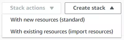
The third way is to just enter Cloud Formation Stacks UI and upload the script from the console by clicking on “Create stack” and then “With new resources (standard)”. AWS console will guide you through the procedure
After you successfully issued our cloud formation scripts to Cloud Formation service, you can see the script progressing in the AWS console:
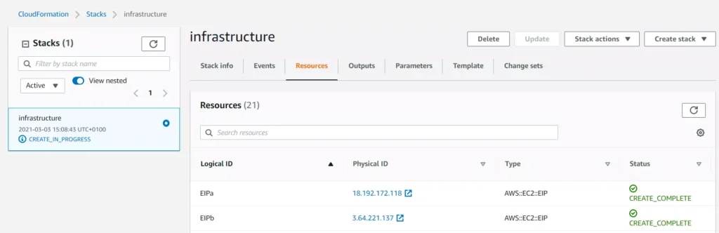
You may find Events and Resource tabs useful while you follow the resource creation procedure.
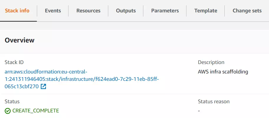
Once all infrastructure components are up and running, you’ll see your stack status marked as CREATE_COMPLETE :
In case your infrastructure definition contained any errors, you will be able to see them in the Cloud Formation console events tab. The status reason column will contain an error message from Cloud Formation or a specific resource service. For example:

For more information on troubleshooting CloudFormation, visit the AWS documentation page .
Summary - cloud infrastructure as code in practice
If you’re reading this, congrats then! You’ve reached the end of this tutorial. We went through the basics of what Infrastructure as Code is, how it works and when to use it. Furthermore, we got a grasp of hands-on experience with Cloud Formation.
As a next step, we strongly encourage you to take a deep dive into AWS Cloud Formation documentation . It will help you adjust the infrastructure to your specific needs and make it even more bulletproof. Eventually, now with all of your infrastructure scripted, you can shout out loud: look ma, no hands!
Supplement - aka. Cloud Formation tips and tricks
When you’re done playing around with your CF Stacks, remember to delete them! Otherwise, AWS will charge you!
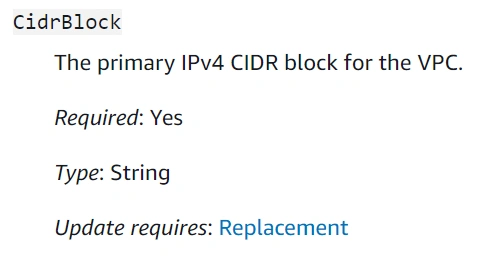
Cloud Formation does not warn you if your updated stack definition might cause infrastructure downtime (resource replacement needed). However, there are two ways to validate that before you deploy. The first one - manual - is to double-check specific resource documentation, especially if the updated property description contains Update requires : Replacement clause. See example for CidrBlock VPC property:
The second way is to use the Change Sets mechanism provided by Cloud Formation. This one would automatically validate the template and tell you how these changes might impact your infrastructure. See the docs .
Cloud Formation does not watch over your resources after they’re created. Therefore, if you make any manual modifications to the resource that is maintained by CF Stack, the stack itself won’t be updated. A situation where the actual infrastructure state is different from its definition (CF script) is called configuration drift. CF comes in handy and lets you see the actual drift for the stack in the console - see this .
If you create your own Cloud Formation script and looking for more examples, the CF registry might come in handy.

Grape Up guides enterprises on their data-driven transformation journey
Ready to ship? Let's talk.
Check related articles
Read our blog and stay informed about the industry's latest trends and solutions.
Automating your enterprise infrastructure. Part 1: Introduction to cloud infrastructure as code (AWS Cloud Formation example)
This is the first article of the series that presents the path towards automated infrastructure deployment. In the first part, we focus on what Infrastructure as Code actually means, its main concepts and gently fill you in on AWS Cloud Formation. In the next part , we get some hands-on experience building and spinning up Enterprise Level Infrastructure as Code.
With a DevOps culture becoming a standard, we face automation everywhere. It is an essential part of our daily work to automate as much as possible. It simplifies and shortens our daily duties, which de facto leads to cost optimization. Moreover, respected developers, administrators, and enterprises rely on automation because it eliminates the probability of human error (which btw takes 2nd place when it comes to security breach causes ).
Additionally, our infrastructure gets more and more complicated as we evolve towards cloud-native and microservice architectures. That is why Infrastructure as code (IaC) came up. It’s an answer to the growing complexity of our systems.
What you’ll find in this article:
- We introduce you to the IaC concept - why do we need it?
- You’ll get familiar with the AWS tool for IaC: Cloud Formation
Why do we need to automate our enterprise infrastructure?
Let’s start with short stories. Close eyes and imagine this:
Sunny morning, your brand new startup service is booming. A surge of dollars flows into Your bank account. The developers have built nice microservice-oriented infrastructure, they’ve configured AWS infrastructure, all pretty shiny. Suddenly, You receive a phone call from someone who says that Amazon's cleaning lady slipped into one of the AWS data centers, fall on the computing rack, therefore the whole Availability Zone went down. Your service is down, users are unhappy.
You tell your developers to recreate the infrastructure in a different data center as fast as they can. Well, it turns out that it’s not possible as fast as you would wish. Last time, it took them a week to spin up the infrastructure, which consists of many parts… you’re doomed.
The story is an example of Disaster Recovery , or rather a lack of it. No one thought that anything might go wrong. But as Murphy’s law says: Anything that can go wrong will go wrong
The other story:
As a progressive developer, you’re learning bleeding-edge cloud technologies to keep up with changing requirements for your employer. You decided to use AWS. Following Michal's tutorial , you happily created your enterprise-level infrastructure. After a long day, you cheerfully lay down to bed. The horror begins when you enter your bank account at the end of the month. Seems that Amazon charged you, for the resources you didn’t delete.
You think these scenarios are unreal? Get to know these stories:
How do You avoid these scenarios? The simple answer to that is IaC.
Infrastructure as Code
Infrastructure as Code is a way to create a recipe for your infrastructure. Normally, a recipe consists of two parts: ingredients and directions/method on how to turn ingredients into the actual dish. IaC is similar, except the narration is a little bit different.
In practice, IaC says:
Keep your IaC scripts (infrastructure components definition) right next to your application code in the Git repository. Think about those definitions as simple text files containing descriptions of your infrastructure. In comparison to the metaphor above, IaC scripts (infrastructure components definitions) are ingredients .
IaC also tells you this:
Use or build tools that will seamlessly turn your IaC scripts into actual cloud resources. So translating that: use or build tools that will seamlessly turn your ingredients (IaC scripts) into a dish (cloud resources).
Nowadays, most IaC tools do the infrastructure provisioning for you and keep it idempotent . So, you just have to prepare the ingredients. Sounds cool, right?
Technically speaking, IaC states that similarly to the automated application build & deployment processes and tools, we should have processes and tools targeted for automated infrastructure deployment .
An important thing to note here is that the approach described above leans you towards GitOps and trunk-based CICD . It is not a coincidence that these concepts are often listed one next to the other. Eventually, this is a big part of what DevOps is all about.
Still not sure how IoC is beneficial to you? See this:
During the HacktOberFest conference, Michal has been setting up the infrastructure manually - live during his lecture. It took him around 30 minutes - even though Michal is an experienced player.
Using cloud formation scripts, the same infrastructure is up and running in ~5 minutes , besides it doesn’t mean that we have to continuously watch over the script being processed. We can just fire and forget, go, have a coffee for the remaining 4 minutes and 50 seconds.
To sum up:
30/5 = 6
Your infrastructure boots up 6 times faster and you have some extra free time. Eventually, it boils down only to the question if you can afford such a waste.
With that being said, we can clearly see that IaC is the foundation on top of which enterprises may implement:
- Highly Available systems
- Disaster recovery
- predictable deployments
- faster time to prod
- CI/CD
- Cost optimization
Note that IaC is just a guideline, and IaC tools are just tools that enable you to achieve the before-mentioned goals faster and better. No tool does the actual work for you.
Regardless of your specific needs, either you build enterprise infrastructure and want to have HA and DR or you just deploy your first application to the cloud and reduce the cost of it, IoC is beneficial for you.
Which IaC tool to use?
There are many IaC tool offerings on the market. Each claim to be the best one. Only to satisfy our AWS deployment automation, we can go with Terraform, AWS Cloud Formation, Ansible and many many more. Which one to use? There is no straight answer, as always in IT: it depends . We recommend doing a few PoC, try out various tools and afterward decide which one fits you best.
How do we do it? Cloud Formation
As aforementioned we need to transcribe our infrastructure into code. So, how do we do it?
First, we need a tool for that. So there it is, the missing piece of Enterprise level AWS Infrastructure - Cloud Formation . It’s an AWS native IaC tool commonly used to automate infrastructure deployment.
Simply put, AWS Cloud Formation scripts are simple text files containing definitions of AWS resources that your infrastructure utilizes (EC2, S3, VPC, etc.). In Cloud Formation these text files are called Templates.
Well… ok, actually Cloud Formation is a little bit more than that. It’s also an AWS service that accepts CF scripts and orchestrates AWS to spin up all of the resources you requested in the right order (simply, automates the clicking in the console). Besides, it gives you live insight into the requested resource status.
Cloud formation follows the notion of declarative infrastructure definitions. On the contrary to an imperative approach in which You say how to provision infrastructure, declaratively you just specify what is the expected result. The knowledge of how to spin up requested resources lies on the AWS side.
If You followed Michal Kapiczynski’s tutorials , the Cloud Formation scripts presented underneath are just all his heavy work, written down to ~500 lines of yml file that you can keep in the repository right next to your application.
Note: Further reading requires you to either see Michals articles before or basic knowledge of AWS.
Enterprise Level Infrastructure Overview
There are many expectations from Enterprise Level infrastructure. From our use case standpoint, we’ll guarantee High Availability, by deploying our infrastructure in two separate AWS Data Centers (Availability Zones) and provide data redundancy by database replication. The picture presented above visualizes the target state of our Enterprise Level Infrastructure.
TLDR; If You’re here just to see the finished Cloud Formation script, please go ahead and visit this GitHub repository .
We've decided to split up our infrastructure setup into two parts (scripts) called Templates . The first part includes AWS resources necessary to construct a network stack. The latter collects application-specific resources: virtual machines, database, and load balancer. In cloud formation nomenclature, each individual set of tightly related resources is called Stack .
Stack usually contains all resources necessary to implement planned functionality. It can consist of: VPC, Subnets, EC2 instances, Load Balancers, etc. This way, we can spin up and tear down all of the resources at once with just one click (or one CLI command).
Each Template can be parametrized. To achieve easy scaling capabilities and disaster recovery, we’ll introduce the Availability Zone parameter. It will allow us to deploy the infrastructure in any AWS data center all around the world just by changing the parameter value.
As you will see through the second part of the guide , Cloud Formation scripts include a few extra resources in comparison to what was originally shown in Michal’s Articles . That’s because AWS creates these resources automatically for you under the hood when you create the infrastructure manually. But since we’re doing the automation, we have to define these resources explicitly.
Sources:
- https://docs.aws.amazon.com/AWSCloudFormation/latest/UserGuide/gettingstarted.templatebasics.html
- https://martinfowler.com/bliki/InfrastructureAsCode.html
- https://docs.microsoft.com/en-us/azure/devops/learn/what-is-infrastructure-as-code
How to run Selenium BDD tests in parallel with AWS Lambda
Have you ever felt annoyed because of the long waiting time for receiving test results? Maybe after a few hours, you’ve figured out that there had been a network connection issue in the middle of testing, and half of the results can go to the trash? That may happen when your tests are dependent on each other or when you have plenty of them and execution lasts forever. It's quite a common issue. But there’s actually a solution that can not only save your time but also your money - parallelization in the Cloud.
How it started
Developing UI tests for a few months, starting from scratch, and maintaining existing tests, I found out that it has become something huge that will be difficult to take care of very soon. An increasing number of test scenarios made every day led to bottlenecks. One day when I got to the office, it turned out that the nightly tests were not over yet. Since then, I have tried to find a way to avoid such situations.
A breakthrough was the presentation of Tomasz Konieczny during the Testwarez conference in 2019. He proved that it’s possible to run Selenium tests in parallel using AWS Lambda. There’s actually one blog that helped me with basic Selenium and Headless Chrome configuration on AWS. The Headless Chrome is a light-weighted browser that has no user interface. I went a step forward and created a solution that allows designing tests in the Behavior-Driven Development process and using the Page Object Model pattern approach, run them in parallel, and finally - build a summary report.
Setting up the project
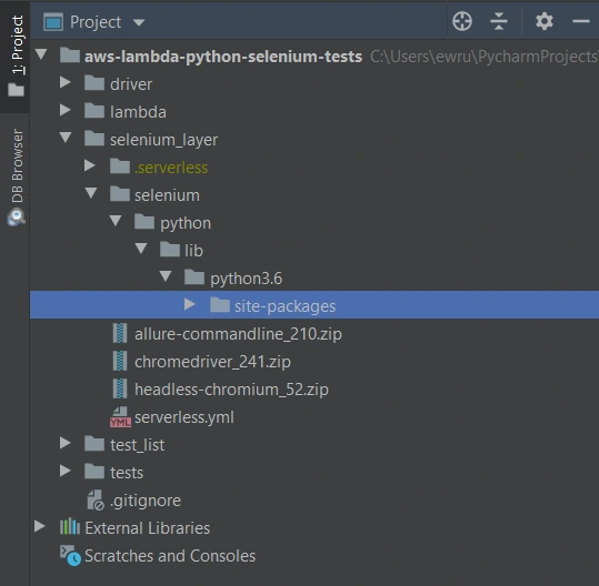
The first thing we need to do is signing up for Amazon Web Services. Once we have an account and set proper values in credentials and config files (.aws directory), we can create a new project in PyCharm, Visual Studio Code, or in any other IDE supporting Python. We’ll need at least four directories here. We called them ‘lambda’, ‘selenium_layer’, ‘test_list’, ‘tests’ and there’s also one additional - ‘driver’, where we keep a chromedriver file, which is used when running tests locally in a sequential way.
In the beginning, we’re going to install the required libraries. Those versions work fine on AWS, but you can check newer if you want.
requirements.txt
allure_behave==2.8.6
behave==1.2.6
boto3==1.10.23
botocore==1.13.23
selenium==2.37.0
What’s important, we should install them in the proper directory - ‘site-packages’.
We’ll need also some additional packages:
Allure Commandline ( download )
Chromedriver ( download )
Headless Chromium ( download )
All those things will be deployed to AWS using Serverless Framework, which you need to install following the docs . The Serverless Framework was designed to provision the AWS Lambda Functions, Events, and infrastructure Resources safely and quickly. It translates all syntax in serverless.yml to a single AWS CloudFormation template which is used for deployments.
Architecture - Lambda Layers
Now we can create a serverless.yml file in the ‘selenium-layer’ directory and define Lambda Layers we want to create. Make sure that your .zip files have the same names as in this file. Here we can also set the AWS region in which we want to create our Lambda functions and layers.
serverless.yml
service: lambda-selenium-layer
provider:
name: aws
runtime: python3.6
region: eu-central-1
timeout: 30
layers:
selenium:
path: selenium
CompatibleRuntimes: [
"python3.6"
]
chromedriver:
package:
artifact: chromedriver_241.zip
chrome:
package:
artifact: headless-chromium_52.zip
allure:
package:
artifact: allure-commandline_210.zip
resources:
Outputs:
SeleniumLayerExport:
Value:
Ref: SeleniumLambdaLayer
Export:
Name: SeleniumLambdaLayer
ChromedriverLayerExport:
Value:
Ref: ChromedriverLambdaLayer
Export:
Name: ChromedriverLambdaLayer
ChromeLayerExport:
Value:
Ref: ChromeLambdaLayer
Export:
Name: ChromeLambdaLayer
AllureLayerExport:
Value:
Ref: AllureLambdaLayer
Export:
Name: AllureLambdaLayer
Within this file, we’re going to deploy a service consisting of four layers. Each of them plays an important role in the whole testing process.
Creating test set
What would the tests be without the scenarios? Our main assumption is to create test files running independently. This means we can run any test without others and it works. If you're following clean code, you'll probably like using the Gherkin syntax and the POM approach. Behave Framework supports both.
What gives us Gherkin? For sure, better readability and understanding. Even if you haven't had the opportunity to write tests before, you will understand the purpose of this scenario.
01.OpenLoginPage.feature
@smoke
@login
Feature: Login to service
Scenario: Login
Given Home page is opened
And User opens Login page
When User enters credentials
And User clicks Login button
Then User account page is opened
Scenario: Logout
When User clicks Logout button
Then Home page is opened
And User is not authenticated
In the beginning, we have two tags. We add them in order to run only chosen tests in different situations. For example, you can name a tag @smoke and run it as a smoke test, so that you can test very fundamental app functions. You may want to test only a part of the system like end-to-end order placing in the online store - just add the same tag for several tests.
Then we have the feature name and two scenarios. Those are quite obvious, but sometimes it’s good to name them with more details. Following steps starting with Given, When, Then and And can be reused many times. That’s the Behavior-Driven Development in practice. We’ll come back to this topic later.
Meantime, let’s check the proper configuration of the Behave project.
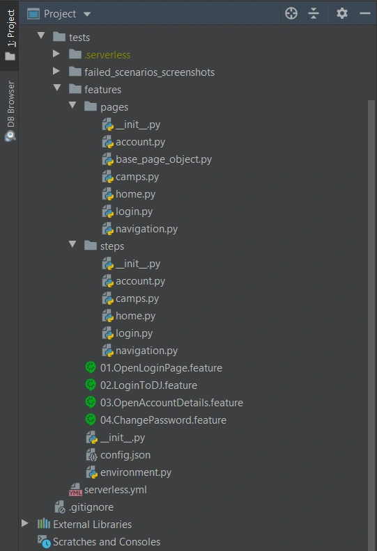
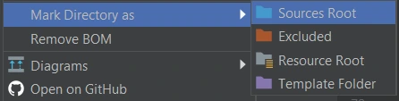
We definitely need a ‘feature’ directory with ‘pages’ and ‘steps’. Make the ‘feature’ folder as Sources Root. Just right-click on it and select the proper option. This is the place for our test scenario files with .feature extension.
It’s good to have some constant values in a separate file so that it will change only here when needed. Let’s call it config.json and put the URL of the tested web application.
config.json
{
"url": "http://drabinajakuba.atthost24.pl/"
}
One more thing we need is a file where we set webdriver options.
Those are required imports and some global values like, e.g. a name of AWS S3 bucket in which we want to have screenshots or local directory to store them in. As far as we know, bucket names should be unique in whole AWS S3, so you should probably change them but keep the meaning.
environment.py
import os
import platform
from datetime import date, datetime
import json
import boto3
from selenium import webdriver
from selenium.webdriver.chrome.options import Options
REPORTS_BUCKET = 'aws-selenium-test-reports'
SCREENSHOTS_FOLDER = 'failed_scenarios_screenshots/'
CURRENT_DATE = str(date.today())
DATETIME_FORMAT = '%H_%M_%S'
Then we have a function for getting given value from our config.json file. The path of this file depends on the system platform - Windows or Darwin (Mac) would be local, Linux in this case is in AWS. If you need to run these tests locally on Linux, you should probably add some environment variables and check them here.
def get_from_config(what):
if 'Linux' in platform.system():
with open('/opt/config.json') as json_file:
data = json.load(json_file)
return data[what]
elif 'Darwin' in platform.system():
with open(os.getcwd() + '/features/config.json') as json_file:
data = json.load(json_file)
return data[what]
else:
with open(os.getcwd() + '\\features\\config.json') as json_file:
data = json.load(json_file)
return data[what]
Now we can finally specify paths to chromedriver and set browser options which also depend on the system platform. There’re a few more options required on AWS.
def set_linux_driver(context):
"""
Run on AWS
"""
print("Running on AWS (Linux)")
options = Options()
options.binary_location = '/opt/headless-chromium'
options.add_argument('--allow-running-insecure-content')
options.add_argument('--ignore-certificate-errors')
options.add_argument('--disable-gpu')
options.add_argument('--headless')
options.add_argument('--window-size=1280,1000')
options.add_argument('--single-process')
options.add_argument('--no-sandbox')
options.add_argument('--disable-dev-shm-usage')
capabilities = webdriver.DesiredCapabilities().CHROME
capabilities['acceptSslCerts'] = True
capabilities['acceptInsecureCerts'] = True
context.browser = webdriver.Chrome(
'/opt/chromedriver', chrome_options=options, desired_capabilities=capabilities
)
def set_windows_driver(context):
"""
Run locally on Windows
"""
print('Running on Windows')
options = Options()
options.add_argument('--no-sandbox')
options.add_argument('--window-size=1280,1000')
options.add_argument('--headless')
context.browser = webdriver.Chrome(
os.path.dirname(os.getcwd()) + '\\driver\\chromedriver.exe', chrome_options=options
)
def set_mac_driver(context):
"""
Run locally on Mac
"""
print("Running on Mac")
options = Options()
options.add_argument('--no-sandbox')
options.add_argument('--window-size=1280,1000')
options.add_argument('--headless')
context.browser = webdriver.Chrome(
os.path.dirname(os.getcwd()) + '/driver/chromedriver', chrome_options=options
)
def set_driver(context):
if 'Linux' in platform.system():
set_linux_driver(context)
elif 'Darwin' in platform.system():
set_mac_driver(context)
else:
set_windows_driver(context)
Webdriver needs to be set before all tests, and in the end, our browser should be closed.
def before_all(context):
set_driver(context)
def after_all(context):
context.browser.quit()
Last but not least, taking screenshots of test failure. Local storage differs from the AWS bucket, so this needs to be set correctly.
def after_scenario(context, scenario):
if scenario.status == 'failed':
print('Scenario failed!')
current_time = datetime.now().strftime(DATETIME_FORMAT)
file_name = f'{scenario.name.replace(" ", "_")}-{current_time}.png'
if 'Linux' in platform.system():
context.browser.save_screenshot(f'/tmp/{file_name}')
boto3.resource('s3').Bucket(REPORTS_BUCKET).upload_file(
f'/tmp/{file_name}', f'{SCREENSHOTS_FOLDER}{CURRENT_DATE}/{file_name}'
)
else:
if not os.path.exists(SCREENSHOTS_FOLDER):
os.makedirs(SCREENSHOTS_FOLDER)
context.browser.save_screenshot(f'{SCREENSHOTS_FOLDER}/{file_name}')
Once we have almost everything set, let’s dive into single test creation. Page Object Model pattern is about what exactly hides behind Gherkin’s steps. In this approach, we treat each application view as a separate page and define its elements we want to test. First, we need a base page implementation. Those methods will be inherited by all specific pages. You should put this file in the ‘pages’ directory.
base_page_object.py
from selenium.webdriver.common.action_chains import ActionChains
from selenium.webdriver.support.ui import WebDriverWait
from selenium.webdriver.support import expected_conditions as EC
from selenium.common.exceptions import *
import traceback
import time
from environment import get_from_config
class BasePage(object):
def __init__(self, browser, base_url=get_from_config('url')):
self.base_url = base_url
self.browser = browser
self.timeout = 10
def find_element(self, *loc):
try:
WebDriverWait(self.browser, self.timeout).until(EC.presence_of_element_located(loc))
except Exception as e:
print("Element not found", e)
return self.browser.find_element(*loc)
def find_elements(self, *loc):
try:
WebDriverWait(self.browser, self.timeout).until(EC.presence_of_element_located(loc))
except Exception as e:
print("Element not found", e)
return self.browser.find_elements(*loc)
def visit(self, url):
self.browser.get(url)
def hover(self, element):
ActionChains(self.browser).move_to_element(element).perform()
time.sleep(5)
def __getattr__(self, what):
try:
if what in self.locator_dictionary.keys():
try:
WebDriverWait(self.browser, self.timeout).until(
EC.presence_of_element_located(self.locator_dictionary[what])
)
except(TimeoutException, StaleElementReferenceException):
traceback.print_exc()
return self.find_element(*self.locator_dictionary[what])
except AttributeError:
super(BasePage, self).__getattribute__("method_missing")(what)
def method_missing(self, what):
print("No %s here!", what)
That’s a simple login page class. There’re some web elements defined in locator_dictionary and methods using those elements to e.g., enter text in the input, click a button, or read current values. Put this file in the ‘pages’ directory.
login.py
from selenium.webdriver.common.by import By
from .base_page_object import *
class LoginPage(BasePage):
def __init__(self, context):
BasePage.__init__(
self,
context.browser,
base_url=get_from_config('url'))
locator_dictionary = {
'username_input': (By.XPATH, '//input[@name="username"]'),
'password_input': (By.XPATH, '//input[@name="password"]'),
'login_button': (By.ID, 'login_btn'),
}
def enter_username(self, username):
self.username_input.send_keys(username)
def enter_password(self, password):
self.password_input.send_keys(password)
def click_login_button(self):
self.login_button.click()
What we need now is a glue that will connect page methods with Gherkin steps. In each step, we use a particular page that handles the functionality we want to simulate. Put this file in the ‘steps’ directory.
login.py
from behave import step
from environment import get_from_config
from pages import LoginPage, HomePage, NavigationPage
@step('User enters credentials')
def step_impl(context):
page = LoginPage(context)
page.enter_username('test_user')
page.enter_password('test_password')
@step('User clicks Login button')
def step_impl(context):
page = LoginPage(context)
page.click_login_button()
It seems that we have all we need to run tests locally. Of course, not every step implementation was shown above, but it should be easy to add missing ones.
If you want to read more about BDD and POM, take a look at Adrian’s article
All files in the ‘features’ directory will also be on a separate Lambda Layer. You can create a serverless.yml file with the content presented below.
serverless.yml
service: lambda-tests-layer
provider:
name: aws
runtime: python3.6
region: eu-central-1
timeout: 30
layers:
features:
path: features
CompatibleRuntimes: [
"python3.6"
]
resources:
Outputs:
FeaturesLayerExport:
Value:
Ref: FeaturesLambdaLayer
Export:
Name: FeaturesLambdaLayer
This is the first part of the series covering running Parallel Selenium tests on AWS Lambda. More here !
The path towards enterprise level AWS infrastructure – architecture scaffolding
This article is the first one of the mini-series which will walk you through the process of creating an enterprise-level AWS infrastructure. By the end of this series, we will have created an infrastructure comprising a VPC with four subnets in two different availability zones with a client application, backend server, and a database deployed inside. Our architecture will be able to provide scalability and availability required by modern cloud systems. Along the way, we will explain the basic concepts and components of the Amazon Web Services platform. In this article, we will talk about the scaffolding of our architecture to be specific a Virtual Private Cloud (VPC), Subnets, Elastic IP Addresses, NAT gateways, and route tables. The whole series comprises of:
- Part 1 - Architecture Scaffolding (VPC, Subnets, Elastic IP, NAT)
- Part 2 - The Path Towards Enterprise Level AWS Infrastructure – EC2, AMI, Bastion Host, RDS
- Part 3 - Load Balancing and Application Deployment (Elastic Load Balancer)
The cloud, as once explained in the Silicon Valley tv-series, is “this tiny little area which is becoming super important and in many ways is the future of computing.” This would be accurate, except for the fact that it is not so tiny and the future is now. So let’s delve into the universe of cloud computing and learn how to build highly available, secure and fault-tolerant cloud systems, how to utilize the AWS platform for that, what are its key components and how to deploy your applications on AWS.
Cloud computing
Over the last years, the IT industry underwent a major transformation in which most of the global enterprises moved away from their traditional IT infrastructures towards the cloud. The main reason behind that is the flexibility and scalability which comes with cloud computing, understood as provisioning of computing services such as servers, storage, databases, networking, analytic services, etc. over the Internet ( the cloud ). In this model organizations only pay for the cloud resources they are actually using and do not need to manage the physical infrastructure behind it. There are many cloud platform providers on the market with the major players being Amazon Web Services (AWS), Microsoft Azure and Google Cloud. This article focuses on services available on AWS, but bear in mind that most of the concepts explained here will have their equivalents on the other platforms.
Infrastructure overview
Let’s start with what we will build throughout this series. The goal is to create a real-life, enterprise-level AWS infrastructure that will be able to host a user management system consisting of a React.js web application, Java Spring Boot server and a relational database.
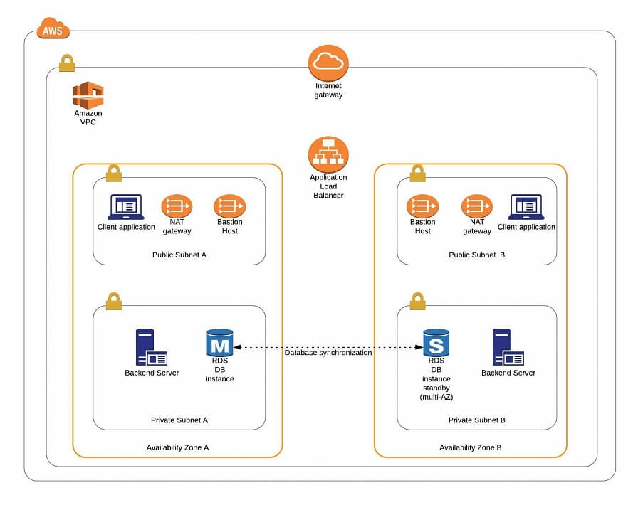
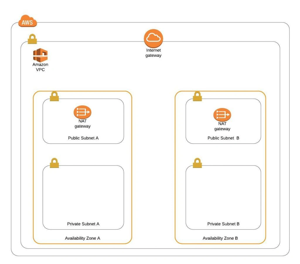
The architecture diagram is shown in figure 1. It comprises a VPC with four subnets (2 public and 2 private) distributed across two different availability zones. In public subnets are hosted a client application, a NAT gateway and a Bastion Host (more on that later), while our private subnets contain backend server and database instances. The infrastructure also includes Internet Gateway to enable access to the Internet from our VPC and a Load Balancer. The reasoning behind placing the backend server and database in private subnets is to protect those instances from being directly exposed to the Internet as they may contain sensitive data. Instead, they will only have private IP addresses and be behind a NAT gateway and a public-facing Elastic Load Balancer. Presented infrastructure provides a high level of scalability and availability through the introduction of redundancy with instances deployed in two different availability zones and the use of auto-scaling groups which provide automatic scaling and health management of the system.
Figure 2 presents the view of the user management web application system we will host on AWS:
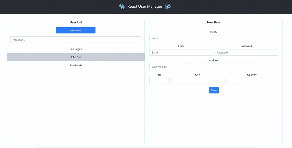
The applications can be found on GitHub.
In this part of the article series, we will focus on the scaffolding of the infrastructure, namely allocating elastic IP addresses, setting up the VPC, creating the subnets, configuring NAT gateways and route tables.
AWS Free Tier Note
AWS provides its new users with a 12-month free tier, which gives customers the ability to use their services up to specified limits free of charge. Those limits include 750 hours per month of t2.micro size EC2 instances, 5GB of Amazon S3 storage, 750 hours of Amazon RDS per month, and much more. In the AWS Management Console, Amazon usually provides indicators in which resource choices are part of the free tier, and throughout this series, we will stick to those. If you want to be sure you will not exceed the free tier limits, remember to stop your EC2 and RDS instances whenever you finish working on AWS. You can also set up a billing alert that will notify you if you exceed the specified limit.
AWS theory
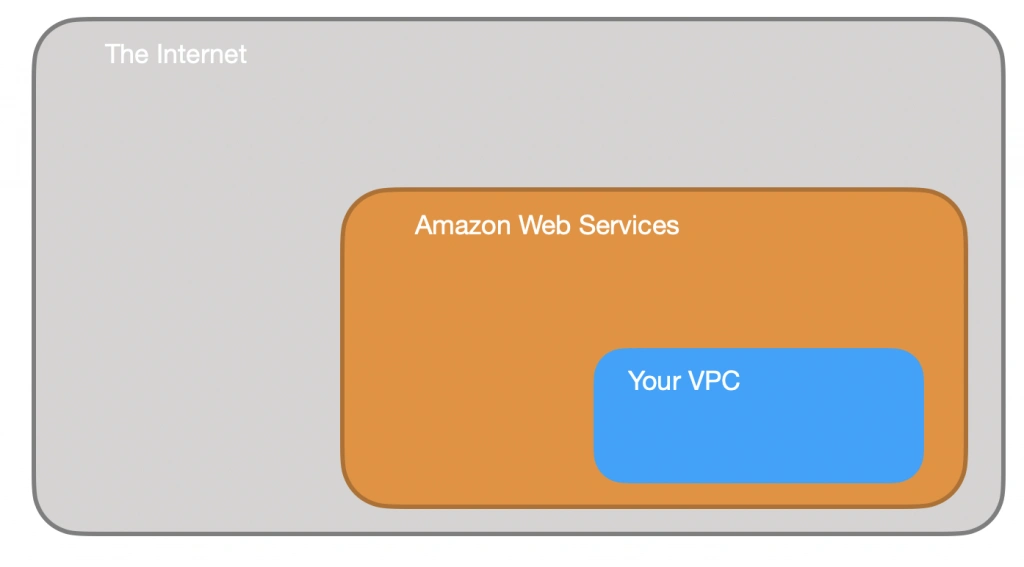
1. VPC
The first step of our journey into the wide world of the AWS infrastructure is getting to know Amazon Virtual Private Cloud (VPC). VPC allows developers to create a virtual network in which they can launch resources and have them logically isolated from other VPCs and the outside world. Within the VPC your resources have private IP addresses with which they can communicate with one another. You can control the access to all those resources inside the VPC and route outgoing traffic as you like.
Access to the VPC is configured with the use of several key structures:
Security groups - They basically work like mini firewalls defining allowed incoming and outgoing IP addresses and ports. They can be attached at the instance level, be shared among many instances and provide the possibility to allow access from other security groups instead of IPs.
Routing tables - Routing tables are responsible for determining where the network traffic from a subnet or gateway should be directed. There is a main route table associated with your VPC, and you can define custom routing tables for your subnets and gateways.
Network Access Control List (Network ACL) - It acts as an IP filtering table for incoming and outgoing traffic and can be used as an additional security layer on top of security groups. Network ACLs act similarly to the security groups, but instead of applying rules on the instance level, they apply them to the entire VPC or subnet.
2. Subnets
Instances cannot be launched directly into a VPC. They need to live inside subnets. A Subnet is an additional isolated area that has its own CIDR block, routing table, and Network Access Control List. Subnets allow you to create different behaviors in the same VPC. For instance, you can create a public subnet that can be accessed and have access to the public internet and a private subnet that is not accessible through the Internet and must go through a NAT (Network Address Translation) gateway in order to access the outside world.
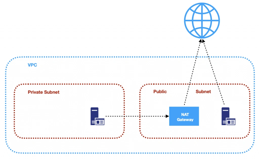
3. NAT (Network Address Transfer) gateway
NAT Gateways are used in order to enable instances located in private subnets to connect to the Internet or other AWS services, while still preventing direct connections from the Internet to those instances. NAT may be useful for example when you need to install or upgrade software or OS on EC2 instances running in private subnets. AWS provides a NAT gateway managed service which requires very little administrative effort. We will use it while setting up our infrastructure.
4. Elastic IP
AWS provides a concept of Elastic IP Address which is used to facilitate the management of dynamic cloud computing. Elastic IP Address is a public, static IP Address that is associated with your AWS account and can be easily allocated to one of your EC2 instances. The idea behind it is that the address is not strongly associated with your instance but instead elasticity of the address allows in a case of any failure in the system to swiftly remap the address to another healthy instance in your account.
5. AWS Region
AWS Regions are geographical areas in which AWS has data centers. Regions are divided into Availability Zones (AZ) which are independent data centers placed relatively close to each other. Availability Zones are used to provide redundancy and data replication. The choice of AWS region for your infrastructure should be determined to take into account factors such as:
- Proximity - you would usually want your application to be deployed close to your region of operation for latency or regulatory reasons.
- Cost - different regions come with different pricing.
- Feature selection - not all services are available in all regions, this is especially the case for newly introduced features.
- Several availability zones - all regions have at least 2 AZ, but some of them have more. Depending on your needs, this may be a key factor.
Practice
AWS Region
Let’s commence with a selection of the AWS region to operate in. In the top right corner of the AWS Management Console, you can choose a region. At this point, it does not really matter which region you choose (as discussed earlier, it may for your organization). However, it is important to note that you will always only view resources launched in the currently selected region.
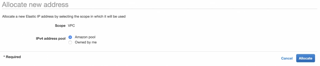
Elastic IP
The next step is the allocation of an elastic IP address. For that purpose, go into the AWS Management console, and find the VPC service. In the left menu bar, under the Virtual Private Cloud section, you should see the Elastic IPs link. There you can allocate a new address owned by yourself or from the pool of Amazon’s available addresses.
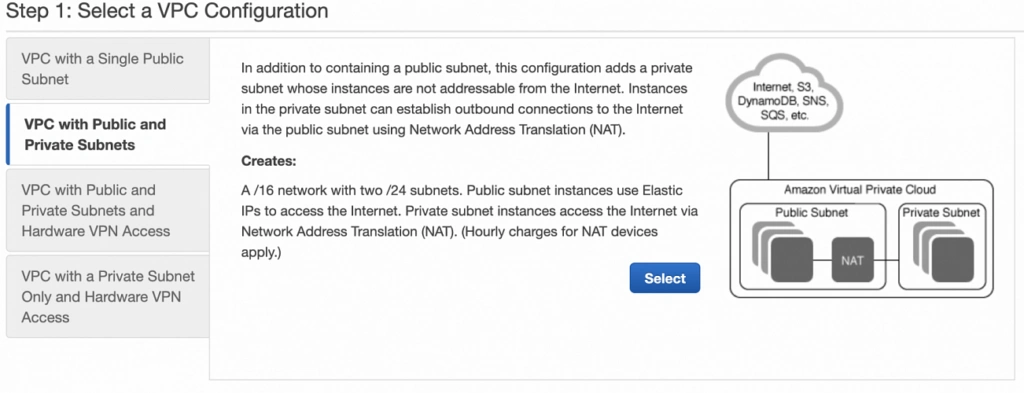
Availability Zone A configuration
Next, let’s create our VPC and subnets. For now, we are going to set up only Availability Zone A and we will work on High Availability after the creation of the VPC. So go again into the VPC service dashboard and click the Launch VPC Wizard button. You will be taken to the screen where you can choose what kind of a VPC configuration you want Amazon to set you up with. In order to match our target architecture as closely as possible, we are going to choose VPC with Public and Private Subnets .
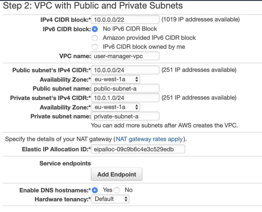
The next screen allows you to set up your VPC configuration details such as:
- name,
- CIDR block,
- details of the subnets:
- name,
- IP address range - a subset of the VPC CIDR range,
- availability zone,
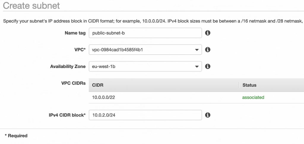
As shown in the architecture diagram (fig. 1), we need 4 subnets in 2 different availability zones. So let’s set our VPC CIDR to 10.0.0.0/22, and have our subnets as follows:
- public-subnet-a: 10.0.0.0/24 (zone A)
- private-subnet-a: 10.0.1.0/24 (zone A)
- public-subnet-b: 10.0.2.0/24 (zone B)
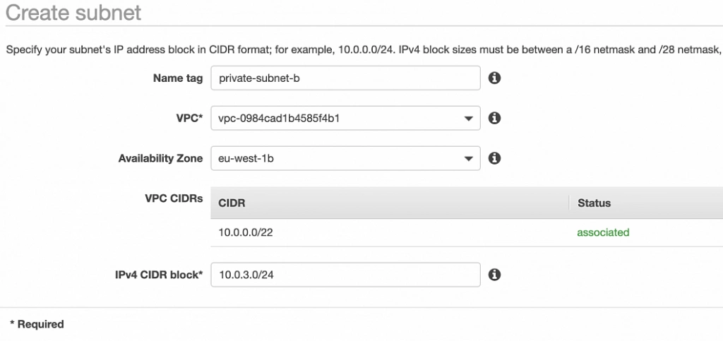
- private-subnet-b: 10.0.3.0/24 (zone B)
Set everything up as shown in figure 7. The important aspects to note here are the choice of the same availability zone for public and private subnets, and the fact that Amazon will automatically set us up with a NAT gateway for which we just need to specify our previously allocated Elastic IP Address. Now, click the Create VPC button, and Amazon will configure your VPC.
NAT gateway
When the creation of the VPC is over, go to the NAT Gateways section, and you should see the gateway created for you by AWS. To make it more recognizable, let us edit its Name tag to nat-a .

Route tables
Amazon also configured Route Tables for your VPC. Go to the Route Tables section, and you should have there two route tables associated with your VPC. One of them is the main route table of your VPC, and the second one is currently associated with your public-subnet-a. We will modify that setting a bit.
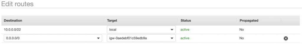
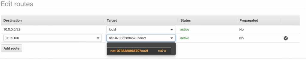
First, select the main route table, go to the routes tab and click Edit routes . There are currently two entries. The first one means Any IP address referencing local VPC CIDR should resolve locally and we shouldn’t modify it. The second one is pointing to the NAT gateway, but we will change it to configure the Internet Gateway of our VPC in order to let outgoing traffic reach the outside world.
Next, go to the Subnet Associations tab and associate the main route table with public-subnet-a. You can also edit its Name tag to main-rt . Then, select the second route table associated with your VPC, edit its routes to route every outgoing Internet request to the nat-a gateway as shown in figure 10. Associate this route table with private-subnet-a and edit its Name tag to private-a-rt .
Availability Zone B Configuration
Well done, availability zone A is configured. In order to provide High Availability, we need to set everything up in the second availability zone as well. The first step is the creation of the subnets. Go again to a VPC dashboard in the AWS management console and in the left menu bar find the Subnets section. Now, click the Create subnet button and configure everything as shown in figures 11 and 12.
public-subnet-b
private-subnet-b
NAT gateway
For availability zone B we need to create the NAT gateway manually. For that, find the NAT Gateways section in the left menu bar of the VPC dashboard, and click Create NAT Gateway . Select public-subnet-b , allocate EIP and add a Name tag with value nat-b .
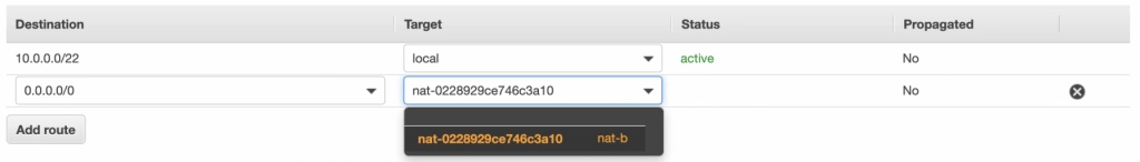
Route tables
The last step is the configuration of the route tables for the subnets in availability zone B. For that, go to the Route Tables section again. Our public-subnet-b is going to have the same routing rules as the public-subnet-a, so let’s add a new association to our main-rt table for public-subnet-b. Then, click the Create route table button, name it private-b-rt , choose our VPC and click create . Next, select the newly created table go to the Routes tab and Edit routes by analogy with the private-a-rt table, but instead of directing every outside going request to nat-a gateway route it to nat-b (fig. 13).
In the end, you should have three route tables associated with your VPC as shown in figure 14.

Summary
That’s it, the scaffolding of our VPC is ready. The diagram shown in fig.15 presents a view of the created infrastructure. It is now ready for the creation of required EC2 instances, Bastion Hosts, configuration of an RDS database and deployment of our applications, which we will do in the next part of the series .
Sources:
- https://azure.microsoft.com/en-us/overview/what-is-cloud-computing/
- https://aws.amazon.com/what-is-aws/
- https://docs.aws.amazon.com/AWSEC2/latest/UserGuide/elastic-ip-addresses-eip.html
- https://docs.aws.amazon.com/vpc/latest/userguide/VPC_Route_Tables.html
- https://docs.aws.amazon.com/vpc/latest/userguide/VPC_SecurityGroups.html#DefaultSecurityGroup
- https://docs.aws.amazon.com/vpc/latest/userguide/vpc-network-acls.html
- https://medium.com/@datapath_io/elastic-ip-static-ip-public-ip-whats-the-difference-8e36ac92b8e7
- https://cloudacademy.com/blog/aws-bastion-host-nat-instances-vpc-peering-security/
- https://aws.amazon.com/blogs/aws/internal-elastic-load-balancers/
- https://aws.amazon.com/quickstart/architecture/linux-bastion/
- https://aws.amazon.com/blogs/security/securely-connect-to-linux-instances-running-in-a-private-amazon-vpc/
- http://thebluenode.com/exposing-private-ec2-instances-behind-public-elastic-load-balancer-elb-aws
- https://app.pluralsight.com/library/courses/aws-developer-getting-started/table-of-contents
- https://app.pluralsight.com/library/courses/aws-developer-designing-developing/table-of-contents
- https://app.pluralsight.com/library/courses/aws-networking-deep-dive-vpc/table-of-contents
- https://datanextsolutions.com/blog/using-nat-gateways-in-aws/
- https://docs.aws.amazon.com/vpc/latest/userguide/vpc-nat-gateway.html
Interested in our services?
Reach out for tailored solutions and expert guidance.