Android Automotive OS 13: How to build and run the latest OS on Raspberry Pi 4B

Building an Android Automotive OS might not be a difficult task on its own, but the lack of good tutorials makes it exceptionally hard. It only gets harder if you don't have at hand any specialized hardware like R-Car or Dragonboard. However, you can easily get a Raspberry Pi - a small ARM-powered, multi-usage computer and a perfect candidate to run AAOS. To make the process easier for everyone struggling with this kind of task, in this article, I'll explain step-by-step how to build and run the latest version: Android Automotive OS 13.
Let's get started!
Prerequisites
To build the system, you will need a Linux. You can use WSL or MacOS (remember, you need a case-sensitive file system), but pure Linux is the best option.
Hardware
As in the previous article , you need a Raspberry Pi 4B microcomputer, a power adapter (or you can power it from your PC with a USB cable), a memory card, and a display. It's nice to have a touchscreen, but you can use your mouse and, optionally, a keyboard if more convenient.
Another nice-to-have element is a USB-TTL bridge for debugging. Find my previous article for more details on how to use it.
TL;DR;
If you're looking for the effortless way, go to https://github.com/grapeup/aaos_local_manifest and follow the readme. There are just a few commands to download, build and create a writeable IMG file for your Raspberry. But you need a few hours to download and build it anyway. Warning! It may not start if you won’t adjust the display settings (see below for details).
Adjusting AOSP to make it AAOS
This project is based on Raspberry Vanilla by KonstaT - a great AOSP port for Raspberry Pi. It covers everything you need to run a pure Android on your Raspberry - an adjusted kernel, hardware drivers, etc. However, there is no automotive build, so you need to construct it.
There are four repositories in github.com/grapeup regarding AAOS – three forks based on Raspberry Vanilla and one new one.
The repository aaos_local_manifest contains a list of modified and new repositories. All significant changes are located in device/brcm/rpi4 and device/brcm/rpi4-car projects defined in the manifest_brcm_rpi4.xml file. In the readme of this repository, you'll find steps to clone and build the project.
The next repository, aaos_device_brcm_rpi4 , contains three elements:
The first and most important is to utilize the new rpi4-car project and remove conflicting items from the base project.
In the aosp_rpi4.mk file, there is a new line
$(call inherit-product, device/brcm/rpi4-car/rpi4_car.mk)
to include a new project.
In the device.mk file, the product characteristic is changed to " automotive,nosdcard " , and all custom overlays are removed, along with the overlay directory next to the file.
In the manifest.xml file, the " android.hardware.automotive.vehicle " HAL (Hardware Abstraction Layer) is added.
The second element is to configure the build for the display I use . I had to set the screen resolution in vendor.prop and set the screen density in BoardConfig.mk . You probably don’t need such changes if you use a standard PC monitor, or you need some other one for your custom display. Be aware that the system won’t start at all if the resolution configured here is not supported by your display.
The last element contains my regional/language settings in aosp_rpi4.mk . I've decided to use this file, as it's not automotive-related, and to leave it in the code to show how to adjust it if needed.
The main part
The most major changes are located in the aaos_device_brcm_rpi4_car repository.
The rpi4_car.mk file is based on device/generic/car/common/car.mk with few changes.
Conditional, special settings for the Generic System Images are removed along with the emulator configuration ( device/generic/car/common/config.ini ) and the emulator audio package ( android.hardware.audio.service-caremu ) .
Instead, you need a mixture of vendor-specific and board-specific components, not included in the common/car makefile designed for an emulator.
Android Automotive OS is strictly coupled with an audio engine, so you need to add an automotive audio control package (android.hardware.automotive.audiocontrol@2.0-service ) to make it work, even if you don’t want to connect any speakers to your board. Also, AAOS uses a special display controller with the ability to use two displays at the same time ( android.frameworks.automotive.display@1.0-service ) , so you need to include it too. The next part is SELinux policy for real boards (not an emulator).
BOARD_SEPOLICY_DIRS += device/generic/car/common/sepolicy
Then you need to add permissions to a few pre-installed, automotive-oriented packages, to allow them to run in the system or user spaces.
PRODUCT_COPY_FILES += device/google/cuttlefish/shared/auto/preinstalled-packages-product-car-cuttlefish.xml:$(TARGET_COPY_OUT_PRODUCT)/etc/sysconfig/preinstalled-packages-product-car-cuttlefish.xml
The next component is EVS - Exterior View System introduced to AAOS 13. Even if you don’t really want to connect multiple cameras to the system so far, you have to include the default implementation of the component and configure it to work as a mock.
  DEVICE_PACKAGE_OVERLAYS += device/google/cuttlefish/shared/auto/overlay
  ENABLE_EVS_SERVICE ?= true
  ENABLE_MOCK_EVSHAL ?= true
  ENABLE_CAREVSSERVICE_SAMPLE ?= true
  ENABLE_SAMPLE_EVS_APP ?= true
  ENABLE_CARTELEMETRY_SERVICE ?= true
  CUSTOMIZE_EVS_SERVICE_PARAMETER := true
  PRODUCT_PACKAGES += android.hardware.automotive.evs@1.1-service
  PRODUCT_COPY_FILES += device/google/cuttlefish/shared/auto/evs/init.evs.rc:$(TARGET_COPY_OUT_VENDOR)/etc/init/init.evs.rc
  BOARD_SEPOLICY_DIRS += device/google/cuttlefish/shared/auto/sepolicy/evs
The last part is to adjust variables for a system when running. You set two system properties directly in the makefile (to allow a forced orientation and to enable the AVRCP Bluetooth profile).
  PRODUCT_SYSTEM_DEFAULT_PROPERTIES += \
  config.override_forced_orient=true \
  persist.bluetooth.enablenewavrcp=false
In the end, you override the following system variables, using predefined and custom overlays.
  PRODUCT_PACKAGE_OVERLAYS += \
  device/brcm/rpi4-car/overlay \
  device/generic/car/common/overlay
Generally speaking, PRODUCT_PACKAGE_OVERLAYS allows us to overwrite any value from a property file located in the source code. For example, in our case the overlay root directory is device/brcm/rpi4-car/overlay , so the file device/brcm/rpi4-car/overlay/frameworks/base/core/res/res/values/config.xml overwrites properties from the file frameworks/base/core/res/res/values/config.xml.
Let’s dive into properties changed.
- frameworks/base/core/res/res/values/config.xml file :
- config_useVolumeKeySounds disables usage of hardware volume keys, as they are not present in our setup,
- config_voice_capable enables data-only mode, as there is no possibility to make a voice call from our board,
- config_sms_capable disables SMS capabilities for the same reason,
- networkAttributes and radioAttributes sets the system to use WiFi, Bluetooth and ethernet connections only, as there is no GSM modem onboard,
- config_longPressOnPowerBehavior disables long-press on a power button, as there is no power button connected,
- config_disableUsbPermissionDialogs disables USB permission screen, as it shouldn’t be used in the AAOS,
- config_defaultUiModeType enables the automotive launcher by default,
- config_defaultNightMode enables night mode as the default one.
- frameworks/base/packages/SettingsProvider/res/values/defaults.xml file:
- def_wifi_on enables WiFi by default,
- def_accelerometer_rotation sets the default orientation,
- def_auto_time enables obtaining time from the Internet when connected,
- def_screen_brightness sets the default screen brightness,
- def_bluetooth_on enables Bluetooth by default,
- def_location_mode allows applications to use location services by default,
- def_lockscreen_disabled disables the lockscreen,
- def_stay_on_while_plugged_in sets the device to stay enabled all the time.
-
packages/apps/Car/LatinIME/res/layout/input_keyboard.xmlkeyTextColorPrimaryandtextColorparameters to adjust it. -
packages/apps/Car/LatinIME/res/values/colors.xmlsets colors or symbol characters on the default keyboard and the letter/symbols switch on the bottom right corner. -
packages/apps/Car/SystemUI/res/values/colors.xml sets the background color of the status bar quick settings to make the default font color readable. -
packages/apps/Car/SystemUI/res/values/config.xml
- packages/apps/Settings/res/values/config.xml file :
- config_show_call_volume disables volume control during calls,
- config_show_charging_sounds disables charging sounds,
- config_show_top_level_battery disables battery level icon.
- packages/modules/Wifi/service/ServiceWifiResources/res/values/config.xml enables 5Ghz support for the WiFi.
-
packages/services/Car/service/res/values/config.xmldisables running a dedicated application when the system starts up or a driver is changed.
You can read more about each of those settings in the comments in the original files which those settings came from.
The very last repository is aaos_android_hardware_interfaces . You don’t need it, but there is one useful property hardcoded here. In Android, there is a concept called HAL – Hardware Abstraction Layer. For AAOS, there is VHAL - Vehicle Hardware Abstraction Layer. It is responsible, among others, for HVAC - Heating, Ventilation, and Air Conditioning. In our setup, there is no vehicle hardware and no physical HVAC, so you use android.hardware.automotive.vehicle@V1-emulator-service whose default implementation is located under hardware/interfaces/automotive/vehicle . To change the default units used by HVAC from imperial to rest-of-the-world, you need to adjust the hardware/interfaces/automotive/vehicle/aidl/impl/default_config/include/DefaultConfig.h file.
Building
The building process for AAOS 13 for Raspberry Pi is much easier than the one for AAOS 11. The kernel is already precompiled and there is much less to do.
Just call those three commands:
  . build/envsetup.sh
  lunch aosp_rpi4-userdebug
  make bootimage systemimage vendorimage
On a Windows laptop (using WSL, of course) with the i7-12850HX processor and 32GB RAM, it takes around 1 hour and 40 minutes to accomplish the build.
Creating a bootable SD card
There are two options – with or without the mkimg.sh script. The script is located under device/brcm/rpi4 directory and linked in the main directory of the project as rpi4-mkimg.sh . The script creates a virtual image and puts 4 partitions inside - boot, system, vendor , and userdata . It's useful because you can use Raspberry Pi Imager to write it into an SD card however, it has a few limitations. The image always has 7GB (you can change it by adjusting the IMGSIZE variable in the script), so you won't use the rest of your card, no matter how big it is. Besides that, you always need to write 7GB to your card - even if you have to update only a single partition, and including writing zeros to an empty userdata partition.
The alternative way is to write it on the card by hand. It's tricky under Windows as WSL doesn't contain card reader drivers, but it's convenient in other operating systems. All required files are built in the out/target/product/rpi4 directory. Let's prepare and write the card. Warning! In my system, the SD card is visible as /dev/sdb . Please adjust the commands below not to destroy your data.
OK, let’s clean the card. You need to wipe each partition before wiping the entire device to remove file systems signatures.
  sudo umount /dev/sdb*
  sudo wipefs -a /dev/sdb*
  sudo wipefs -a /dev/sdb
Now let’s prepare the card. This line will use fdisk to create 4 partitions and set flags and filesystems.
echo -e "n\n\n\n\n+128M\na\nt\n0c\nn\n\n\n\n+2G\nn\n\n\n\n+256M\nn\np\n\n\nw\n" | sudo fdisk /dev/sdb
The last step is to write data and prepare the last partition.
  sudo dd if=boot.img of=/dev/sdb1 bs=1M
  sudo dd if=system.img of=/dev/sdb2 bs=1M
  sudo dd if=vendor.img of=/dev/sdb3 bs=1M
  sudo mkfs.ext4 -L userdata /dev/sdb4
  sudo umount /dev/sdb*
Summary
Android Automotive OS is a giant leap for the automotive industry . As there is no production vehicle with AAOS 13 so far, you can experience the future with this manual. What's more, you can do it with a low-budget Raspberry Pi computer. This way, I hope you can develop your applications and play with the system easily without an additional layer of using emulators. Good luck and happy coding!

Grape Up guides enterprises on their data-driven transformation journey
Ready to ship? Let's talk.
Check related articles
Read our blog and stay informed about the industry's latest trends and solutions.
Android Automotive OS 14 is out – build your own emulator from scratch!
Android Automotive OS 14 has arrived, and it marks a significant evolution in the way users interact with their vehicle's system. This version brings enhanced user experience, improved Android API, and better OS-level security (as well as non-automotive Android 14). In this short article, we'll walk you through a tutorial on creating your own emulator from scratch, but first, here are some of the standout features and improvements introduced in Android Automotive OS 14 !
Android Automotive 14 noteworthy new features
- Enhanced UI: Now with an optional, improved home screen adaptation to the portrait mode for better vehicle compatibility.
- Multi-User Upgrades: Support parallel sessions with custom sound zones and multiple displays.
- Remote Access: Enables system wake-up, executes a task and then shutdown via external requests.
- Extended VHAL: More ADAS and non-ADAS properties included to represent activation status and the system state.
- App Quick Actions: A feature that allows applications to showcase quick actions.
- Infotainment Reference Design: The starting point for developers to create apps for Android Automotive OS.
- New Boot Animation: Well, as usual 😊
To learn about all new features provided in Android Automotive 14, follow this link: https://source.android.com/docs/automotive/start/releases/u_udc_release?hl=en
Steps to building an emulator
The best operating system for building an emulator in AAOs is Ubuntu 18.04 or higher. If you use a different operating system, you must follow some extra steps. For instance, you may need to install a repo from https://gerrit.googlesource.com/git-repo instead of using a package manager.
1) You need first to install the required dependencies
sudo apt install git-core gnupg flex bison build-essential zip curl zlib1g-dev libc6-dev-i386 libncurses5 x11proto-core-dev libx11-dev lib32z1-dev libgl1-mesa-dev libxml2-utils xsltproc unzip fontconfig repo
2) Then, configure Git, set your name and email address
git config --global user.name "Your name"
git config --global user.email your@email
3) After configuring Git, you can download source code from a Git repository
repo init -u https://android.googlesource.com/platform/manifest -b android-14.0.0_r54 --partial-clone --clone-filter=blob:limit=10M && repo sync
You can skip ‐‐ partial-clone and ‐‐ clone-filter. However, this will result in longer download times. It’s recommended to check for the latest android-14.0.0_rXX tag before downloading, which can be found on this page: https://android.googlesource.com/platform/manifest/+refs .
Keep in mind that downloading takes a lot of time because the sources take about 150GB even with partial clone and clone-filter enabled.
4) In the next step, set up environment variables using the script provided
. build/envsetup.sh
This method replaces your JAVA_HOME and modifies PATH, so be aware that your console may act differently now.
5) Select the system to build
lunch sdk_car_portrait_x86_64-eng
You can create a landscape build by removing "portrait". Also, change x86_64 to arm64 if you want to run the system on Mac. For more details on building on Mac, check out this article .
6) Create the system and the emulator image
m && m emu_img_zip
The first command will take hours to complete. Take a break: go running, biking, hiking, or whatever drives you. You can modify threat pool usage by the build system with -j parameter, like m -j 16 – the default one is the CPU count of your machine.
7) Copy the emulator image to Android Studio emulator directory
mkdir -p /mnt/c/Users/<user>/AppData/Local/Android/Sdk/system-images/android-34/custom_aaos_14/ && unzip -o out/target/product/emulator_x86_64/sdk-repo-Linux-system-images-eng.dape.zip -d /mnt/c/Users/<user>/AppData/Local/Android/Sdk/system-images/android-34/custom_aaos_14/
I assume you work on a Windows machine with WSL. Please adapt the above commands with your Android/SDK directory if you are working on native Linux.
Create a package.xml file in /mnt/c/Users/<user>/AppData/Local/Android/Sdk/system-images/android-34/custom_aaos_14/x86_64 directory with the this content . The file provided bases on existing package.xml files in other emulator images.
Adjust “tag”, “vendor”, and “display name” in the upper file if needed. Make sure to match <localPackage obsolete="false" path="system-images;android-34;custom_aaos_14;x86_64"> with the path you’d placed the emulator image.
8) Now it’s time to create a new emulator in Android Studio
Open "Device Manager" and select "Create Virtual Device". In the left-hand menu, choose "Automotive" and add a new hardware profile using the button in the lower-left corner of the panel.
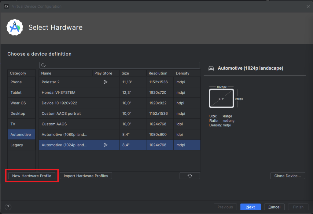
Select “Android Automotive” as a device type. Choose the correct resolution for your build. For example, I selected a resolution of 1152x1536 for a 10-inch device to create a portrait build. Next, allocate at least 1536 MB of RAM to your device. Then, choose only one supported device state - "Portrait" or "Landscape" - according to your build. Finally, disable any unnecessary sensors and skin for AAOS compatibility.
9) Accept and select your new hardware profile. Then, move on to the next step
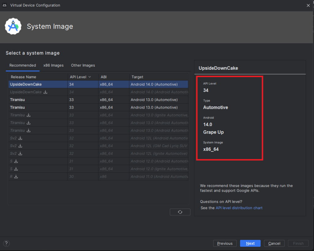
10) Pick your emulator image (you can find it using the tag and vendor configured in package.xml)
11) On the final screen, enter a name and complete the configuration process
12) To start the emulator, go to the "Device Manager" and launch it from there
13) You’re all set! Enjoy!
Get started on creating your very own Android Automotive OS 14 emulator by following the steps outlined in this article. Explore the possibilities of car technology and discover what the future has in store. You can find a AAOS “Hello World” example in our article How to Build Your First App for Android Automotive OS . Start building, try out the various features, and have fun with your new setup!
Android AAOS 14 - EVS network camera
The automotive industry has been rapidly evolving with technological advancements that enhance the driving experience and safety. Among these innovations, the Android Automotive Operating System (AAOS) has stood out, offering a versatile and customizable platform for car manufacturers.
The Exterior View System (EVS) is a comprehensive camera-based system designed to provide drivers with real-time visual monitoring of their vehicle's surroundings. It typically includes multiple cameras positioned around the vehicle to eliminate blind spots and enhance situational awareness, significantly aiding in maneuvers like parking and lane changes. By integrating with advanced driver assistance systems, EVS contributes to increased safety and convenience for drivers.
For more detailed information about EVS and its configuration, we highly recommend reading our article "Android AAOS 14 - Surround View Parking Camera: How to Configure and Launch EVS (Exterior View System)." This foundational article provides essential insights and instructions that we will build upon in this guide.
The latest Android Automotive Operating System , AAOS 14, presents new possibilities, but it does not natively support Ethernet cameras. In this article, we describe our implementation of an Ethernet camera integration with the Exterior View System (EVS) on Android.
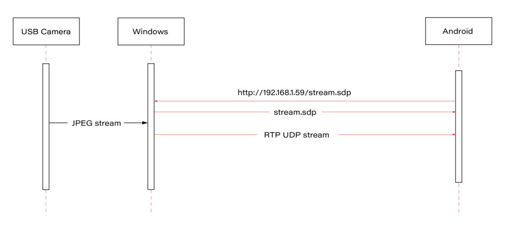
Our approach involves connecting a USB camera to a Windows laptop and streaming the video using the Real-time Transport Protocol (RTP). By employing the powerful FFmpeg software, the video stream will be broadcast and described in an SDP (Session Description Protocol) file, accessible via an HTTP server. On the Android side, we'll utilize the FFmpeg library to receive and decode the video stream, effectively bringing the camera feed into the AAOS 14 environment.
This article provides a step-by-step guide on how we achieved this integration of the EVS network camera, offering insights and practical instructions for those looking to implement a similar solution. The following diagram provides an overview of the entire process:
Building FFmpeg Library for Android
To enable RTP camera streaming on Android, the first step is to build the FFmpeg library for the platform. This section describes the process in detail, using the ffmpeg-android-maker project. Follow these steps to successfully build and integrate the FFmpeg library with the Android EVS (Exterior View System) Driver.
Step 1: Install Android SDK
First, install the Android SDK. For Ubuntu/Debian systems, you can use the following commands:
sudo apt update && sudo apt install android-sdk
The SDK should be installed in /usr/lib/android-sdk .
Step 2: Install NDK
Download the Android NDK (Native Development Kit) from the official website:
https://developer.android.com/ndk/downloads
After downloading, extract the NDK to your desired location.
Step 3: Build FFmpeg
Clone the ffmpeg-android-maker repository and navigate to its directory:
git clone https://github.com/Javernaut/ffmpeg-android-maker.gitcd ffmpeg-android-maker
Set the environment variables to point to the SDK and NDK:
export ANDROID_SDK_HOME=/usr/lib/android-sdk
export ANDROID_NDK_HOME=/path/to/ndk/
Run the build script:
./ffmpeg-android-maker.sh
This script will download FFmpeg source code and dependencies, and compile FFmpeg for various Android architectures.
Step 4: Copy Library Files to EVS Driver
After the build process is complete, copy the .so library files from build/ffmpeg/ to the EVS Driver directory in your Android project:
cp build/ffmpeg/*.so /path/to/android/project/packages/services/Car/cpp/evs/sampleDriver/aidl/
Step 5: Add Libraries to EVS Driver Build Files
Edit the Android.bp file in the aidl directory to include the prebuilt FFmpeg libraries:
cc_prebuilt_library_shared {
    name: "rtp-libavcodec",
    vendor: true,
    srcs: ["libavcodec.so"],
    strip: {
        none: true,
    },
    check_elf_files: false,
}

cc_prebuilt_library {
    name: "rtp-libavformat",
    vendor: true,
    srcs: ["libavformat.so"],
    strip: {
        none: true,
    },
    check_elf_files: false,
}

cc_prebuilt_library {
    name: "rtp-libavutil",
    vendor: true,
    srcs: ["libavutil.so"],
    strip: {
        none: true,
    },
    check_elf_files: false,
}

cc_prebuilt_library_shared {
    name: "rtp-libswscale",
    vendor: true,
    srcs: ["libswscale.so"],
    strip: {
        none: true,
    },
    check_elf_files: false,
}
Add prebuilt libraries to EVS Driver app:
cc_binary {
    name: "android.hardware.automotive.evs-default",
    defaults: ["android.hardware.graphics.common-ndk_static"],
    vendor: true,
    relative_install_path: "hw",
    srcs: [
        ":libgui_frame_event_aidl",
        "src/*.cpp"
    ],
    shared_libs: [
        "rtp-libavcodec",
       	"rtp-libavformat",
       	"rtp-libavutil",
       	"rtp-libswscale",
        "android.hardware.graphics.bufferqueue@1.0",
        "android.hardware.graphics.bufferqueue@2.0",
        android.hidl.token@1.0-utils,

....]
}
By following these steps, you will have successfully built the FFmpeg library for Android and integrated it into the EVS Driver.
EVS Driver RTP Camera Implementation
In this chapter, we will demonstrate how to quickly implement RTP support for the EVS (Exterior View System) driver in Android AAOS 14. This implementation is for demonstration purposes only. For production use, the implementation should be optimized, adapted to specific requirements, and all possible configurations and edge cases should be thoroughly tested. Here, we will focus solely on displaying the video stream from RTP.
The main files responsible for capturing and decoding video from USB cameras are implemented in the EvsV4lCamera and VideoCapture classes. To handle RTP, we will copy these classes and rename them to EvsRTPCamera and RTPCapture . RTP handling will be implemented in RTPCapture . We need to implement four main functions:
bool open(const char* deviceName, const int32_t width = 0, const int32_t height = 0);
void close();
bool startStream(std::function<void(RTPCapture*, imageBuffer*, void*)> callback = nullptr);
void stopStream();
We will use the official example from the FFmpeg library, https://github.com/FFmpeg/FFmpeg/blob/master/doc/examples/demux_decode.c, which decodes the specified video stream into RGBA buffers. After adapting the example, the RTPCapture.cpp file will look like this:
#include "RTPCapture.h"
#include <android-base/logging.h>

#include <errno.h>
#include <error.h>
#include <fcntl.h>
#include <memory.h>
#include <stdio.h>
#include <stdlib.h>
#include <sys/ioctl.h>
#include <sys/mman.h>
#include <unistd.h>

#include <cassert>
#include <iomanip>
#include <stdio.h>
#include <stdlib.h>
#include <iostream>
#include <fstream>
#include <sstream>

static AVFormatContext *fmt_ctx = NULL;
static AVCodecContext *video_dec_ctx = NULL, *audio_dec_ctx;
static int width, height;
static enum AVPixelFormat pix_fmt;

static enum AVPixelFormat out_pix_fmt = AV_PIX_FMT_RGBA;

static AVStream *video_stream = NULL, *audio_stream = NULL;
static struct SwsContext *resize;
static const char *src_filename = NULL;

static uint8_t *video_dst_data[4] = {NULL};
static int video_dst_linesize[4];
static int video_dst_bufsize;

static int video_stream_idx = -1, audio_stream_idx = -1;
static AVFrame *frame = NULL;
static AVFrame *frame2 = NULL;
static AVPacket *pkt = NULL;
static int video_frame_count = 0;

int RTPCapture::output_video_frame(AVFrame *frame)
{
    LOG(INFO) << "Video_frame: " << video_frame_count++
              << " ,scale height: " << sws_scale(resize, frame->data, frame->linesize, 0, height, video_dst_data, video_dst_linesize);
if (mCallback) {
imageBuffer buf;
        buf.index = video_frame_count;
        buf.length = video_dst_bufsize;
        mCallback(this, &buf, video_dst_data[0]);
    }

    return 0;
}

int RTPCapture::decode_packet(AVCodecContext *dec, const AVPacket *pkt)
{
    int ret = 0;

    ret = avcodec_send_packet(dec, pkt);
    if (ret < 0) {
        return ret;
    }

    // get all the available frames from the decoder
    while (ret >= 0) {
        ret = avcodec_receive_frame(dec, frame);
        if (ret < 0) {
            if (ret == AVERROR_EOF || ret == AVERROR(EAGAIN))
            {
                return 0;
            }
            return ret;
        }

        // write the frame data to output file
        if (dec->codec->type == AVMEDIA_TYPE_VIDEO) {
            ret = output_video_frame(frame);
        }

        av_frame_unref(frame);
        if (ret < 0)
            return ret;
    }

    return 0;
}

int RTPCapture::open_codec_context(int *stream_idx,
                              AVCodecContext **dec_ctx, AVFormatContext *fmt_ctx, enum AVMediaType type)
{
    int ret, stream_index;
    AVStream *st;
    const AVCodec *dec = NULL;

    ret = av_find_best_stream(fmt_ctx, type, -1, -1, NULL, 0);
    if (ret < 0) {
        fprintf(stderr, "Could not find %s stream in input file '%s'\n",
                av_get_media_type_string(type), src_filename);
        return ret;
    } else {
        stream_index = ret;
        st = fmt_ctx->streams[stream_index];

        /* find decoder for the stream */
        dec = avcodec_find_decoder(st->codecpar->codec_id);
        if (!dec) {
            fprintf(stderr, "Failed to find %s codec\n",
                    av_get_media_type_string(type));
            return AVERROR(EINVAL);
        }

        /* Allocate a codec context for the decoder */
        *dec_ctx = avcodec_alloc_context3(dec);
        if (!*dec_ctx) {
            fprintf(stderr, "Failed to allocate the %s codec context\n",
                    av_get_media_type_string(type));
            return AVERROR(ENOMEM);
        }

        /* Copy codec parameters from input stream to output codec context */
        if ((ret = avcodec_parameters_to_context(*dec_ctx, st->codecpar)) < 0) {
            fprintf(stderr, "Failed to copy %s codec parameters to decoder context\n",
                    av_get_media_type_string(type));
            return ret;
        }

        av_opt_set((*dec_ctx)->priv_data, "preset", "ultrafast", 0);
        av_opt_set((*dec_ctx)->priv_data, "tune", "zerolatency", 0);

        /* Init the decoders */
        if ((ret = avcodec_open2(*dec_ctx, dec, NULL)) < 0) {
            fprintf(stderr, "Failed to open %s codec\n",
                    av_get_media_type_string(type));
            return ret;
        }
        *stream_idx = stream_index;
    }

    return 0;
}

bool RTPCapture::open(const char* /*deviceName*/, const int32_t /*width*/, const int32_t /*height*/) {
    LOG(INFO) << "RTPCapture::open";

    int ret = 0;
    avformat_network_init();

    mFormat = V4L2_PIX_FMT_YUV420;
    mWidth = 1920;
    mHeight = 1080;
    mStride = 0;

    /* open input file, and allocate format context */
    if (avformat_open_input(&fmt_ctx, "http://192.168.1.59/stream.sdp", NULL, NULL) < 0) {
        LOG(ERROR) << "Could not open network stream";
        return false;
    }
    LOG(INFO) << "Input opened";

    isOpened = true;

    /* retrieve stream information */
    if (avformat_find_stream_info(fmt_ctx, NULL) < 0) {
        LOG(ERROR) << "Could not find stream information";
        return false;
    }
    LOG(INFO) << "Stream info found";

    if (open_codec_context(&video_stream_idx, &video_dec_ctx, fmt_ctx, AVMEDIA_TYPE_VIDEO) >= 0) {
        video_stream = fmt_ctx->streams[video_stream_idx];

        /* allocate image where the decoded image will be put */
        width = video_dec_ctx->width;
        height = video_dec_ctx->height;
        pix_fmt = video_dec_ctx->sw_pix_fmt;

        resize = sws_getContext(width, height, AV_PIX_FMT_YUVJ422P,
                                width, height, out_pix_fmt, SWS_BICUBIC, NULL, NULL, NULL);

        LOG(ERROR) << "RTPCapture::open pix_fmt: " << video_dec_ctx->pix_fmt
                   << ", sw_pix_fmt: " << video_dec_ctx->sw_pix_fmt
                   << ", my_fmt: " << pix_fmt;

        ret = av_image_alloc(video_dst_data, video_dst_linesize,
                             width, height, out_pix_fmt, 1);

        if (ret < 0) {
            LOG(ERROR) << "Could not allocate raw video buffer";
            return false;
        }
        video_dst_bufsize = ret;
    }

    av_dump_format(fmt_ctx, 0, src_filename, 0);

    if (!audio_stream && !video_stream) {
        LOG(ERROR) << "Could not find audio or video stream in the input, aborting";
        ret = 1;
        return false;
    }

    frame = av_frame_alloc();
    if (!frame) {
        LOG(ERROR) << "Could not allocate frame";
        ret = AVERROR(ENOMEM);
        return false;
    }
    frame2 = av_frame_alloc();

    pkt = av_packet_alloc();
    if (!pkt) {
        LOG(ERROR) << "Could not allocate packet";
        ret = AVERROR(ENOMEM);
        return false;
    }

    return true;
}

void RTPCapture::close() {
    LOG(DEBUG) << __FUNCTION__;
}

bool RTPCapture::startStream(std::function<void(RTPCapture*, imageBuffer*, void*)> callback) {
    LOG(INFO) << "startStream";
    if(!isOpen()) {
        LOG(ERROR) << "startStream failed. Stream not opened";
        return false;
    }

    stop_thread_1 = false;
    mCallback = callback;
    mCaptureThread = std::thread([this]() { collectFrames(); });

    return true;
}

void RTPCapture::stopStream() {
    LOG(INFO) << "stopStream";
    stop_thread_1 = true;
    mCaptureThread.join();
    mCallback = nullptr;
}

bool RTPCapture::returnFrame(int i) {
    LOG(INFO) << "returnFrame" << i;
    return true;
}

void RTPCapture::collectFrames() {
    int ret = 0;

    LOG(INFO) << "Reading frames";
    /* read frames from the file */
    while (av_read_frame(fmt_ctx, pkt) >= 0) {
        if (stop_thread_1) {
            return;
        }

        if (pkt->stream_index == video_stream_idx) {
            ret = decode_packet(video_dec_ctx, pkt);
        }
        av_packet_unref(pkt);
        if (ret < 0)
            break;
    }
}

int RTPCapture::setParameter(v4l2_control&) {
    LOG(INFO) << "RTPCapture::setParameter";
    return 0;
}

int RTPCapture::getParameter(v4l2_control&) {
    LOG(INFO) << "RTPCapture::getParameter";
    return 0;
}

std::set<uint32_t> RTPCapture::enumerateCameraControls() {
    LOG(INFO) << "RTPCapture::enumerateCameraControls";
    std::set<uint32_t> ctrlIDs;
    return std::move(ctrlIDs);
}

void* RTPCapture::getLatestData() {
    LOG(INFO) << "RTPCapture::getLatestData";
    return nullptr;
}

bool RTPCapture::isFrameReady() {
    LOG(INFO) << "RTPCapture::isFrameReady";
    return true;
}

void RTPCapture::markFrameConsumed(int i) {
    LOG(INFO) << "RTPCapture::markFrameConsumed frame: " << i;
}

bool RTPCapture::isOpen() {
    LOG(INFO) << "RTPCapture::isOpen";
    return isOpened;
}
Next, we need to modify EvsRTPCamera to use our RTPCapture class instead of VideoCapture . In EvsRTPCamera.h , add:
#include "RTPCapture.h"
And replace:
VideoCapture mVideo = {};
with:
RTPCapture mVideo = {};
In EvsRTPCamera.cpp , we also need to make changes. In the forwardFrame(imageBuffer* pV4lBuff, void* pData) function, replace:
mFillBufferFromVideo(bufferDesc, (uint8_t*)targetPixels, pData, mVideo.getStride());
with:
memcpy(targetPixels, pData, pV4lBuff->length);
This is because the VideoCapture class provides a buffer from the camera in various YUYV pixel formats. The mFillBufferFromVideo function is responsible for converting the pixel format to RGBA. In our case, RTPCapture already provides an RGBA buffer. This is done in the
int RTPCapture::output_video_frame(AVFrame *frame) function using sws_scale from the FFmpeg library.
Now we need to ensure that our RTP camera is recognized by the system. The EvsEnumerator class and its enumerateCameras function are responsible for detecting cameras. This function adds all video files from the /dev/ directory.
To add our RTP camera, we will append the following code at the end of the enumerateCameras function:
if (addCaptureDevice("rtp1")) {
    ++captureCount;
}
This will add a camera with the ID "rtp1" to the list of detected cameras, making it visible to the system.
The final step is to modify the EvsEnumerator: :openCamera function to direct the camera with the ID "rtp1" to the RTP implementation. Normally, when opening a USB camera, an instance of the EvsV4lCamera class is created:
pActiveCamera = EvsV4lCamera::Create(id.data());
In our example, we will hardcode the ID check and create the appropriate object:
if (id == "rtp1") {
    pActiveCamera = EvsRTPCamera::Create(id.data());
} else {
    pActiveCamera = EvsV4lCamera::Create(id.data());
}
With this implementation, our camera should start working. Now we need to build the EVS Driver application and push it to the device along with the FFmpeg libraries:
mmma packages/services/Car/cpp/evs/sampleDriver/
adb push out/target/product/rpi4/vendor/bin/hw/android.hardware.automotive.evs-default /vendor/bin/hw/
Launching the RTP Camera
To stream video from your camera, you need to install FFmpeg ( https://www.ffmpeg.org/download.html#build-windows ) and an HTTP server on the computer that will be streaming the video.
Start FFmpeg (example on Windows):
ffmpeg -f dshow -video_size 1280x720 -i video="USB Camera" -c copy -f rtp rtp://192.168.1.53:8554
where:
- -video_size is video resolution
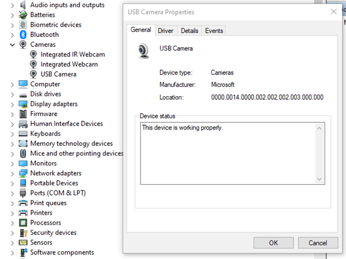
- "USB Camera" is the name of the camera as it appears in the Device Manager
- "-c copy" means that individual frames from the camera (in JPEG format) will be copied to the RTP stream without changes. Otherwise, FFmpeg would need to decode and re-encode the image, introducing unnecessary delays.
- "rtp://192.168.1.53:8554": 192.168.1.53 is the IP address of our Android device. You should adjust this accordingly. Port 8554 can be left as the default.
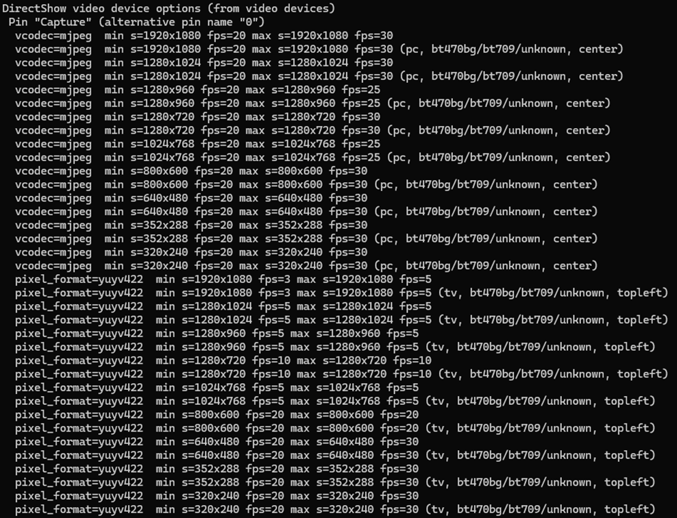
After starting FFmpeg, you should see output similar to this on the console:
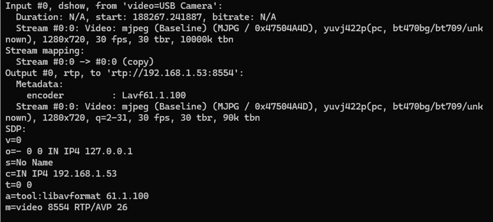
Here, we see the input, output, and SDP sections. In the input section, the codec is JPEG, which is what we need. The pixel format is yuvj422p, with a resolution of 1920x1080 at 30 fps. The stream parameters in the output section should match.
Next, save the SDP section to a file named stream.sdp on the HTTP server. Our EVS Driver application needs to fetch this file, which describes the stream.
In our example, the Android device should access this file at: http://192.168.1.59/stream.sdp
The exact content of the file should be:
v=0
o=- 0 0 IN IP4 127.0.0.1
s=No Name
c=IN IP4 192.168.1.53
t=0 0
a=tool:libavformat 61.1.100
m=video 8554 RTP/AVP 26
Now, restart the EVS Driver application on the Android device:
killall android.hardware.automotive.evs-default
Then, configure the EVS app to use the camera "rtp1". For detailed instructions on how to configure and launch the EVS (Exterior View System), refer to the article "Android AAOS 14 - Surround View Parking Camera: How to Configure and Launch EVS (Exterior View System)".
Performance Testing
In this chapter, we will measure and compare the latency of the video stream from a camera connected via USB and RTP.
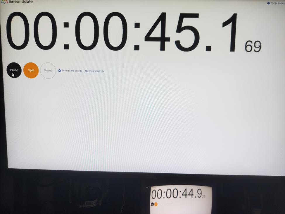
How Did We Measure Latency?
- Setup Timer: Displayed a timer on the computer screen showing time with millisecond precision.
- Camera Capture: Pointed the EVS camera at this screen so that the timer was also visible on the Android device screen.
- Snapshot Comparison: Took photos of both screens simultaneously. The time displayed on the Android device was delayed compared to the computer screen. The difference in time between the computer and the Android device represents the camera's latency.
This latency is composed of several factors:
- Camera Latency: The time the camera takes to capture the image from the sensor and encode it into the appropriate format.
- Transmission Time: The time taken to transmit the data via USB or RTP.
- Decoding and Display: The time to decode the video stream and display the image on the screen.
Latency Comparison
Below are the photos showing the latency:
USB Camera
RTP Camera
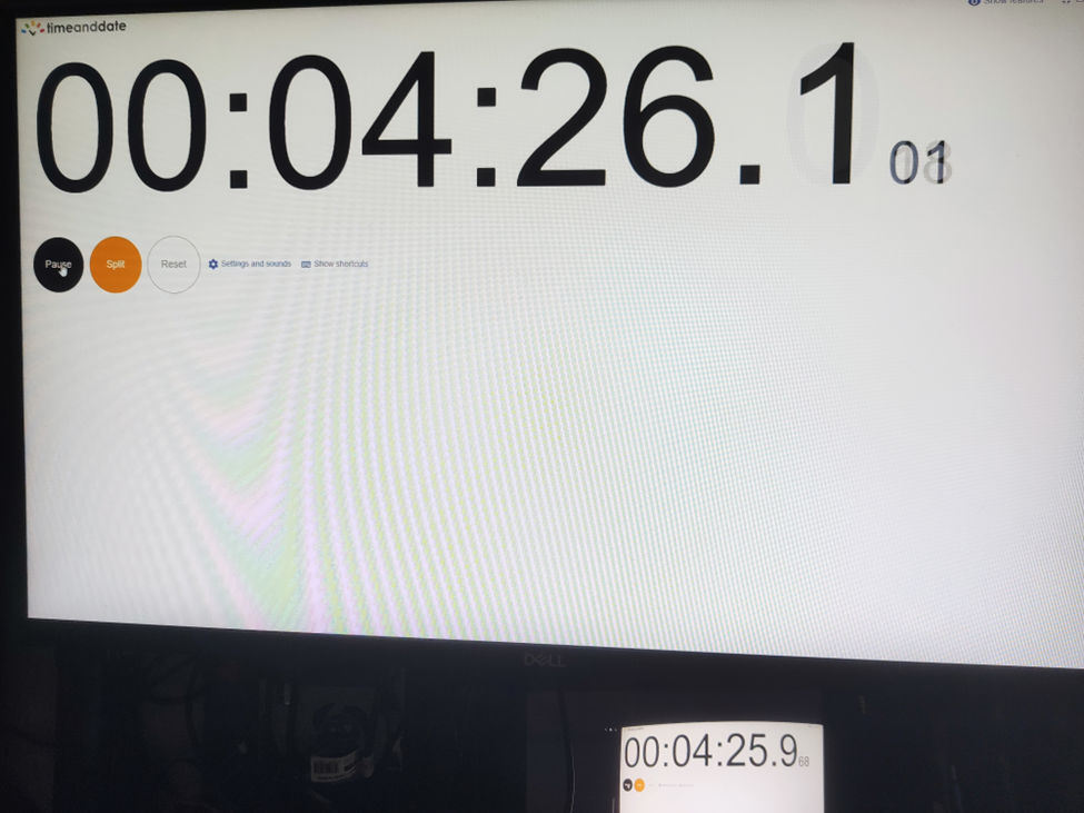
From these measurements, we found that the average latency for a camera connected via USB to the Android device is 200ms , while the latency for the camera connected via RTP is 150ms . This result is quite surprising.
The reasons behind these results are:
- The EVS implementation on Android captures video from the USB camera in YUV and similar formats, whereas FFmpeg streams RTP video in JPEG format.
- The USB camera used has a higher latency in generating YUV images compared to JPEG. Additionally, the frame rate is much lower. For a resolution of 1280x720, the YUV format only supports 10 fps, whereas JPEG supports the full 30 fps.
All camera modes can be checked using the command:
ffmpeg -f dshow -list_options true -i video="USB Camera"
Conclusion
This article has taken you through the comprehensive process of integrating an RTP camera into the Android EVS (Exterior View System) framework, highlighting the detailed steps involved in both the implementation and the performance evaluation.
We began our journey by developing new classes, EvsRTPCamera and RTPCapture , which were specifically designed to handle RTP streams using FFmpeg. This adaptation allowed us to process and stream real-time video effectively. To ensure our system recognized the RTP camera, we made critical adjustments to the EvsEnumerator class. By customizing the enumerateCameras and openCamera functions, we ensured that our RTP camera was correctly instantiated and recognized by the system.
Next, we focused on building and deploying the EVS Driver application, including the necessary FFmpeg libraries, to our target Android device. This step was crucial for validating our implementation in a real-world environment. We also conducted a detailed performance evaluation to measure and compare the latency of video feeds from USB and RTP cameras. Using a timer displayed on a computer screen, we captured the timer with the EVS camera and compared the time shown on both the computer and Android screens. This method allowed us to accurately determine the latency introduced by each camera setup.
Our performance tests revealed that the RTP camera had an average latency of 150ms, while the USB camera had a latency of 200ms. This result was unexpected but highly informative. The lower latency of the RTP camera was largely due to the use of the JPEG format, which our particular USB camera handled less efficiently due to its slower YUV processing. This significant finding underscores the RTP camera's suitability for applications requiring real-time video performance, such as automotive surround view parking systems, where quick response times are essential for safety and user experience.
Interested in our services?
Reach out for tailored solutions and expert guidance.