
Software Engineer with a degree in Computer Science and over ten years of commercial development experience. Experience across the automotive software lifecycle, from concept and design through to development and testing. Previous projects have included Linux, Windows, and QNX C/C++ development, automotive development, AUTOSAR, network protocols analysis and implementation low-level development and hardware bring-up, Qt, and multimedia application development.
Read articles
Running LLMs on-device with Qualcomm Snapdragon 8 Elite
Why on-device LLM inference is changing automotive AI?
Large Language Models have traditionally lived in the cloud - massive GPU clusters serving billions of requests through APIs. But for industries like automotive, cloud dependency is not always acceptable. Connectivity fails in tunnels, rural areas, and underground parking structures. Latency spikes are unacceptable for safety-critical driver interactions. And sending private conversation data to external servers raises serious compliance and data sovereignty concerns. This is precisely where on-device LLM inference and edge AI become not just attractive, but essential.
What if the LLM could run directly on a chip inside the vehicle?
We set out to prove this is not only possible, but production-ready. Using Qualcomm’s Snapdragon 8 Elite platform with its dual Hexagon NPU cores, we deployed multiple on-device LLM variants on an Android device and built a fully functional edge AI inference server requiring zero cloud connectivity.
Platform and software stack for on-device AI inference
Our setup relies on the following components:
- Chipset: Qualcomm Snapdragon 8 Elite with dual Hexagon NPU cores
- Operating system: Android
- Inference runtime: Qualcomm Genie - a lightweight on-device engine optimized for autoregressive LLM inference on Hexagon NPU
- Model compilation: Qualcomm AI Hub - a cloud service that compiles and optimizes models for specific Snapdragon chipsets
- Application: Custom-built Android service based on Qualcomm's AI Hub Apps reference architecture, extended with an HTTP server interface
The Genie runtime is the critical piece. It takes QNN context binaries - precompiled, quantized model graphs - and executes them on the NPU with minimalCPU overhead. The model never touches a GPU. All heavy computation runs on dedicated AI silicon.
Llama models for edge AI: 3B vs. 8B on-device parameter comparison
We worked with two models from Meta's Llama family, chosen to represent different points on the size-versus-quality spectrum:
Llama 3.2 3B Instruct -a compact 3-billion parameter model. Quantized to W4A16 precision (4-bit weights, 16-bit activations), it fits comfortably in device memory and delivers fast, responsive inference. Ideal for quick interactions - voice command interpretation, short summaries, simple question answering.
Llama 3.1 8B Instruct -a larger 8-billion parameter model with a 2048-token context window. Also quantized to W4A16, it produces noticeably higher quality responses with better reasoning, longer coherent outputs, and more nuanced instruction following.This model represents a sweet spot between capability and on-device feasibility.
Both models were exported through Qualcomm AI Hub as QNN context binaries, each split across five parts for efficient loading and memory management.
Compiling LLMs for Snapdragon 8 Elite with Qualcomm AI Hub
The path from open-source model weights to on-device NPU execution is streamlined through Qualcomm's toolchain. The qai_hub_models Python package provides export scripts for supported models. A single command handles quantization, optimization, and compilation:
python -m
qai_hub_models.models.llama_v3_1_8b_instruct.export--
chipsetqualcomm-snapdragon-8-elite --skip-profiling --
output-dirgenie_bundle
The entire export process - from Hugging Face model to device-readybinaries - takes minutes, not days. This dramatically lowers the barrier to experimenting with different models on-device.
Building a self-contained on-device LLM inference server
Rather than building a traditional Android chat application, we took a more versatile approach. We transformed the device into a network-accessible LLM inference server.

The device runs a lightweight HTTP server as an Android foreground service. It can be reached over USB or Ethernet - any machine on the local network can send prompts and receive streaming responses. In an automotive context, this means the LLM service can be accessed by the vehicle's head unit, a diagnostic tool, or any connected system - without requiring a custom client application.
The server exposes a simple REST API:
- GET/health - service health check
- GET /models - list available models on device
- POST /models/load - load a model into NPU memory
- POST /models/unload - unload a model and freeNPU memory
- POST /generate - send a prompt, receive streaming SSE response
The /generate endpoint uses Server-Sent Events for real-time tokenstreaming. Each token is pushed to the client the moment it is generated,creating a responsive, conversational experience.
The server also hosts a self-contained web interface at the root path.Opening the device's IP address in any browser presents a chat interface where users can select a model, type a prompt, and watch the response appear token by token. No app installation required on the client side. Just a browser and a network connection.


On-device LLM performance: Tokens per second on Snapdragon 8 Elite
The results demonstrate that on-device LLM inference on Snapdragon 8Elite is not just a tech demo - it delivers genuinely usable performance.
Llama 3.2 3B Instruct runs at approximately 10 tokens per second. At this speed, responses feel fluid and interactive. A typical short answer (50–80tokens) appears in under 8 seconds. For voice assistant scenarios - where the user asks a question and expects a spoken answer - this is more than sufficient. The response begins streaming before the user even finishes processing the question mentally.
Llama 3.1 8B Instruct runs at approximately 5 tokens per second. While slower, this is still fast enough for many practical applications. A 100-token response completes in about 20 seconds. More importantly, the quality improvement over the 3B model is substantial - longer coherent reasoning chains, better instruction adherence, and more nuanced responses. For tasks like summarizing a vehicle manual section, explaining a dashboard warning, or having a multi-turn conversation about navigation options, the 8B model's quality advantage justifies the speed tradeoff.
To put these numbers in perspective: 5 tokens per second from an8-billion parameter model running entirely on a mobile chipset, with zero cloud dependency, zero network latency, and complete data privacy. Two years ago, this would have required a server rack.
Optimizing on-device AI: Genie runtime configuration explained
Genie's behavior is tuned through two configuration files that ship alongside each model.
The Genie config (genie_config.json) controls core runtime parameters:context length in tokens, CPU thread count, CPU core affinity via bit mask, and memory mapping settings.
The HTP (Hexagon Tensor Processor - NPU) backend config(htp_backend_ext_config.json) controls NPU-specific settings: which Hexagon NPU core to use (Snapdragon 8 Elite has two), and the performance profile -"burst" for maximum throughput or"sustained_high_performance" for thermal stability during extended sessions.
These configurations provide fine-grained control over the performance-power-thermal tradeoff - essential in automotive environments where sustained operation and thermal management are critical constraints.
Automotive AI use cases enabled by on-device LLM inference
Running an LLM directly in the vehicle opens up application scenarios that are impossible or impractical with cloud-based AI:
Offline voice assistant - a natural language interface that works in tunnels, parking garages, rural areas, and anywhere without cellular coverage.The driver asks a question; the answer comes from the device, not the cloud.
On-board vehicle manual - instead of flipping through a 500-page PDF, the driver or passenger asks "What does the yellow triangle warning light mean?" and gets an immediate, contextual answer.
Predictive maintenance dialogue - the vehicle detects an anomaly and theLLM explains it in natural language: "Your tire pressure is 15% below recommended. This is likely due to the temperature drop overnight. I recommend checking the pressure at your next stop."
Multi-language support - a single quantized multilingual model can serve drivers in any language without requiring separate language packs or cloud translation services.
Privacy-first personal assistant - calendar, contacts, and preferences stay on-device. No conversation transcripts leave the vehicle. Full GDPR compliance by design.
Diagnostic and service support - technicians can query the vehicle's state in natural language during service appointments, without needing specialized diagnostic software.
Key lessons from deploying LLMs on edge hardware
The export toolchain is mature enough for production exploration.Qualcomm AI Hub abstracts away enormous complexity - quantization, graph optimization, NPU code generation - behind a single export command. Going from a Hugging Face model to running inference on a phone takes less than an hour.
Configuration matters. CPU core affinity, thread count, NPU core assignment, memory mapping, and performance profiles all affect throughput, latency, and thermal behavior. There is no universal "best"configuration - it depends on the model, the workload pattern, and the thermal constraints of the deployment environment.
The hardware is ready. Snapdragon 8 Elite's dual Hexagon NPU cores deliver real, practical LLM inference performance. An 8-billion parameter model generating coherent, high-quality text at 5 tokens per second on a mobile chipset - with headroom for optimization - is a remarkable engineering achievement.
The form factor is transformative. An Android device the size of a credit card, drawing a few watts, running a full LLM inference stack accessible over HTTP. For automotive, industrial IoT, and edge computing, this changes what is possible without cloud infrastructure.
Conclusion: On-device LLM inference is ready for production
We set out to answer a simple question: can you run a real, useful LLMon a Snapdragon 8 Elite, entirely on-device, and make it accessible as a service?
The answer is yes.
With Qualcomm's Genie runtime and AI Hub toolchain, we deployed both a3-billion and an 8-billion parameter Llama model on an Android device. We built an HTTP server interface that turns the device into a self-contained LLM appliance - accessible from any browser, any connected system, with zero cloud dependency.
The 3B model at 10 tokens per second is fast enough for real-time voice assistant interactions. The 8B model at 5 tokens per second delivers meaningfully better response quality while remaining practical for conversational use. Both run entirely on the NPU, leaving the CPU and GPU free for other tasks.
For the automotive industry - where privacy, reliability, and offline capability are non-negotiable - on-device LLM inference is no longer a future promise. It is a present reality. The hardware exists. The toolchain exists.The performance is there.
The question is no longer "Can we run an LLM in the car?" It is "What will we build with it?"
FAQ: On-device LLM inference
What is on-device LLM inference?
On-device LLM inference means running a large language model directly on local hardware - such as a mobilechipset or embedded processor - without sending data to cloud servers. This approach delivers lower latency, complete offline capability, and full dataprivacy, since no prompts or responses ever leave the device.
Why is Qualcomm Snapdragon 8 Elite suited for LLM inference?
The Snapdragon 8 Elite features dual Hexagon NPU (Neural Processing Unit) cores specifically designed for AIworkloads. These dedicated cores execute quantized model graphs with minimalCPU and GPU overhead, enabling models with billions of parameters to run at practical speeds entirely on a mobile chipset.
What is the Qualcomm Genie runtime?
Qualcomm Genie is a light weight on-device inference engine optimized for auto regressive LLM inference on Hexagon NPU hardware. It takes precompiled, quantized QNN context binaries and executes them efficiently on the NPU, keeping the CPU and GPU free for other vehicle system tasks.
How fast do LLMs run on Snapdragon 8 Elite?
In our testing, Llama 3.2 3B Instruct achieved approximately 10 tokens per second, and the larger Llama 3.18B Instruct model ran at approximately 5 tokens per second. Both deliver practical, interactive performance suitable for real-world applications such as voice assistants and on-board advisory systems.
What is W4A16 quantization and why does it matter for on-device AI?
W4A16 quantization uses 4-bit precision for model weights and 16-bit precision for activations. This significantly reduces the memory footprint of large language models without a major loss in output quality - making multi-billion parameter models feasible for deployment on mobile hardware and automotive-grade chips.
Can LLMs run in a vehicle without internet connectivity?
Yes. On-device LLM inference runs entirely on the vehicle's local chipset, requiring no network connection. This is critical for automotive applications where connectivity is intermittent -such as tunnels, rural roads, or underground parking - and where real-time,reliable response is non-negotiable.
What is Qualcomm AI Hub?
Qualcomm AI Hub is a cloud-based compilation service that converts open-source model weights into optimized QNN context binaries targeting specific Snapdragon chipsets. It handles quantization, graph optimization, and NPU code generation automatically, reducing the path from a Hugging Face model checkpoint to device-ready binaries to under one hour.
Is on-device AI inference GDPR compliant?
On-device AI inference processes all data locally, meaning no conversation transcripts, voice recordings, or personal data are transmitted to external servers. This architecture supports GDPR compliance by design and is especially relevant for in-vehicle personal assistants, predictive maintenance systems, and any application involving sensitive user data.
Android Automotive OS 11 Camera2 and EVS - Two different camera subsystems up and running
Android Automotive OS, AAOS in short, is a vehicle infotainment operating system that has gained a lot of traction recently, with most of the OEMs around the world openly announcing new versions of their infotainment based on Android. AAOS is based on the AOSP (Android Open Source Project) source code, which makes it fully compatible with Android, with additions that make it more useful in cars – different UI, integration with hardware layer, or vehicle-specific apps.
For OEMs and Tier1s, who are deeply accustomed to infotainment based on QNX/Autosar/Docker/Linux, and software developers working on AAOS apps, it’s sometimes difficult to quickly spin-up the development board or emulator supporting external hardware that has no out-of-the-box emulation built by Google. One of the common examples is camera access, which is missing in the official AAOS emulator these days, but the hardware itself is quite common in modern vehicles – which makes implementation of applications similar to Zoom or MS Teams for AAOS tempting to app developers.
In this article, I will explain how to build a simple test bench based on a cost-effective Raspberry Pi board and AAOS for developers to test their camera application. Examples will be based on AAOS 11 running on Raspberry Pi 4 and our Grape Up repository. Please check our previous article: " Build and Run Android Automotive OS on Raspberry Pi 4B " for a detailed description of how to run AAOS on this board.
Android Automotive OS has 2 different subsystems to access platform cameras: Camera2 and EVS. In this article, I will explain both how we can use it and how to get it running on Android Automotive OS 11.
Exterior View System (EVS)
EVS is a subsystem to display parking and maneuvering camera image. It supports multiple cameras' access and view. The main goal and advantage of that subsystem is that it boots quickly and should display a parking view before 2 seconds, which is required by law.
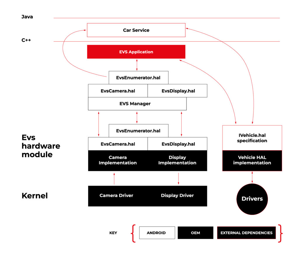
Source https://source.android.com/docs/automotive/camera-hal
As you can see on the attached diagram, low layers of EVS depend on OEM source code. OEM needs to deliver Camera and Display implementation. However, Android delivers a sample application (/hardware/interfaces/automotive/evs/1.0) , which uses Linux V4L2 and OpenGL to grab camera frames and display them. You can find more information about EVS at https://source.android.com/docs/automotive/camera-hal
In our example, we will use samples from Android. Additionally, I assume you build our Raspberry Pi image (see our article ), as it has multiple changes that allow AAOS to reliably run on RPi4 and support its hardware.
You should have a camera connected to your board via USB. Please check if your camera is detected by V4L2. There should be a device file:
/dev/video0
Then, type on the console:
su

setprop persist.automotive.evs.mode 1
This will start the EVS system.
To display camera views:
evs_app
Type Ctrl-C to exit the app and go back to the normal Android view.
Camera2
Camera2 is a subsystem intended for camera access by “normal” Android applications (smartphones, tablets, etc.). It is a common system for all Android applications, recently slowly being replaced by CameraX. The developer of an Android app uses Java camera API to gain access to the camera.
Camera2 has three main layers, which are shown in the diagram below:

Source https://source.android.com/docs/core/camera
Low-level Camera access is implemented in CameraProvider. OEM can implement their own provider or a V4L2 camera driver can be used.
To get Camera2, you should enable it in the Car product make file. In
packages/services/Car/car_product/build/car_base.mk change config.disable_cameraservice to false.
PRODUCT_PROPERTY_OVERRIDES += config.disable_cameraservice=false
After that, rebuild Android:
make ramdisk systemimage vendorimage
Put it in the SD card and boot RPi with it. You will be able to run the “Camera” application on the AAOS screen, see camera output from the connected webcam, and run and debug applications using Camera API.
Summary
Now you know how to run both AAOS camera APIs on the RPi4 board. You can use both APIs to develop automotive applications leveraging cameras and test them using a simple USB webcam, which you may have somewhere on the shelf. If you found this article useful, you can also look at our previous articles about AAOS – both from the application development perspective and the OS perspective . Happy coding!
Exploring Texas Instruments Edge AI: Hardware acceleration for efficient computation
In recent years, the field of artificial intelligence (AI) has witnessed a transformative shift towards edge computing, enabling intelligent decision-making to occur directly on devices rather than relying solely on cloud-based solutions. Texas Instruments, a key player in the semiconductor industry, has been at the forefront of developing cutting-edge solutions for Edge AI. One of the standout features of their offerings is the incorporation of hardware acceleration for efficient computation, which significantly improves the performance of AI models on resource-constrained devices.
Pros and cons of running AI models on embedded devices vs. cloud
In the evolving landscape of artificial intelligence , the decision to deploy models on embedded devices or rely on cloud-based solutions is a critical consideration. This chapter explores the advantages and disadvantages of running AI models on embedded devices, emphasizing the implications for efficiency, privacy, latency, and overall system performance.
Advantages of embedded AI
- Low Latency
One of the primary advantages of embedded AI is low latency. Models run directly on the device, eliminating the need for data transfer to and from the cloud. This results in faster response times, making embedded AI ideal for applications where real-time decision-making is crucial. - Privacy and Security
Embedded AI enhances privacy by processing data locally on the device. This mitigates concerns related to transmitting sensitive information to external servers. Security risks associated with data in transit are significantly reduced, contributing to a more secure AI deployment. - Edge Computing Efficiency
Utilizing embedded AI aligns with the principles of edge computing. By processing data at the edge of the network, unnecessary bandwidth usage is minimized, and only relevant information is transmitted to the cloud. This efficiency is especially beneficial in scenarios with limited network connectivity. What’s more, some problems are very inefficient to solve on cloud-based AI models, for example: video processing with real time output. - Offline Functionality
Embedded AI allows for offline functionality, enabling devices to operate independently of internet connectivity. This feature is advantageous in remote locations or environments with intermittent network access, as it expands the range of applications for embedded AI. - Reduced Dependence on Network Infrastructure
Deploying AI models on embedded devices reduces dependence on robust network infrastructure. This is particularly valuable in scenarios where maintaining a stable and high-bandwidth connection is challenging or cost ineffective. AI feature implemented on the cloud platform will be unavailable in the car after the connection is lost.
Disadvantages of embedded AI
- Lack of Scalability
Scaling embedded AI solutions across a large number of devices can be challenging. Managing updates, maintaining consistency, and ensuring uniform performance becomes more complex as the number of embedded devices increases. - Maintenance Challenges
Updating and maintaining AI models on embedded devices can be more cumbersome compared to cloud-based solutions. Remote updates may be limited, requiring physical intervention for maintenance, which can be impractical in certain scenarios. - Initial Deployment Cost
The initial cost of deploying embedded AI solutions, including hardware and development, can be higher compared to cloud-based alternatives. However, this cost may be offset by long-term benefits, depending on the specific use case and scale. - Limited Computational Power
Embedded devices often have limited computational power compared to cloud servers. This constraint may restrict the complexity and size of AI models that can be deployed on these devices, impacting the range of applications they can support. - Resource Constraints
Embedded devices typically have limited memory and storage capacities. Large AI models may struggle to fit within these constraints, requiring optimization or compromising model size for efficient deployment.
The decision to deploy AI models on embedded devices or in the cloud involves careful consideration of trade-offs. While embedded AI offers advantages in terms of low latency, privacy, and edge computing efficiency, it comes with challenges related to scalability, maintenance, and limited resources.
However, chipset manufacturers are constantly engaged in refining and enhancing their products by incorporating specialized modules dedicated to hardware-accelerated model execution. This ongoing commitment to innovation aims to significantly improve the overall performance of devices, ensuring that they can efficiently run AI models. The integration of these hardware-specific modules not only promises comparable performance but, in certain applications, even superior efficiency.
Deploy AI model on embedded device workflow
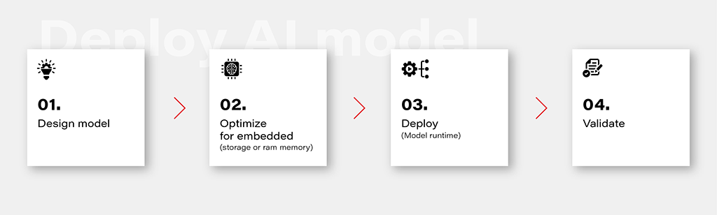
1. Design Model
Designing an AI model is the foundational step in the workflow. This involves choosing the appropriate model architecture based on the task at hand, whether it's classification, regression, or other specific objectives. This is out of the topic for this article.
2. Optimize for Embedded (Storage or RAM Memory)
Once the model is designed, the next step is to optimize it for deployment on embedded devices with limited resources. This optimization may involve reducing the model size, minimizing the number of parameters, or employing quantization techniques to decrease the precision of weights. The goal is to strike a balance between model size and performance to ensure efficient operation within the constraints of embedded storage and RAM memory.
3. Deploy (Model Runtime)
Deploying the optimized model involves integrating it into the embedded system's runtime environment. While there are general-purpose runtime frameworks like TensorFlow Lite and ONNX Runtime, achieving the best performance often requires leveraging dedicated frameworks that utilize hardware modules for accelerated computations. These specialized frameworks harness hardware accelerators to enhance the speed and efficiency of the model on embedded devices.
4. Validate
Validation is a critical stage in the workflow to ensure that the deployed model performs effectively on the embedded device. This involves rigorous testing using representative datasets and scenarios. Metrics such as accuracy, latency, and resource usage should be thoroughly evaluated to verify that the model meets the performance requirements. Validation helps identify any potential issues or discrepancies between the model's behavior in the development environment and its real-world performance on the embedded device.
Deploy model on Ti Edge AI and Jacinto 7
Deploying an AI model on Ti Edge AI and Jacinto 7 involves a series of steps to make the model work efficiently with both regular and specialized hardware. In simpler terms, we'll walk through how the model file travels from a general Linux environment to a dedicated DSP core, making use of special hardware features along the way.
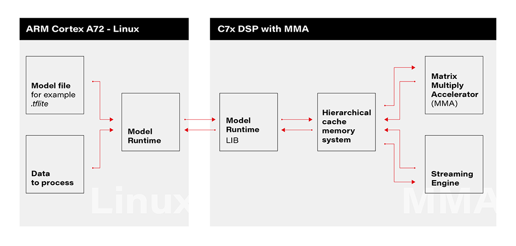
1. Linux Environment on A72 Core: The deployment process initiates within the Linux environment running on the A72 core. Here, a model file resides, ready to be utilized by the application's runtime. The model file, often in a standardized format like .tflite, serves as the blueprint for the AI model's architecture and parameters.
2. Runtime Application on A72 Core: The runtime application, responsible for orchestrating the deployment, receives the model file from the Linux environment. This runtime acts as a proxy between the user, the model, and the specialized hardware accelerator. It interfaces with the Linux environment, handling the transfer of input data to be processed by the model.
3. Connection to C7xDSP Core: The runtime application establishes a connection with its library executing on the C7xDSP core. This library, finely tuned for hardware acceleration, is designed to efficiently process AI models using specialized modules such as the Matrix Multiply Accelerator.
4. Loading Model and Data into Memory: The library on the C7x DSP core receives the model description and input data, loading them into memory for rapid access. This optimized memory utilization is crucial for achieving efficient inference on the dedicated hardware.
5. Computation with Matrix Multiply Accelerator: Leveraging the power of the Matrix Multiply Accelerator, the library performs the computations necessary for model inference. The accelerator efficiently handles matrix multiplications, a fundamental operation in many neural network models.
The matrix multiply accelerator (MMA) provides the following key features:
- Support for a fully connected layer using matrix multiply with arbitrary dimension
- Support for convolution layer using 2D convolution with matrix multiply with read panel Support for ReLU non-linearity layer OTF
- Support for high utilization (>85%) for a typical convolutional neural network (CNN), such as AlexNet, ResNet, and others
- Ability to support any CNN network topologies limited only by memory size and bandwidth
6. Result Return to User via Runtime on Linux: Upon completion of computations, the results are returned to the user through the runtime application on the Linux environment. The inference output, processed with hardware acceleration, provides high-speed, low-latency responses for real-time applications.
Object recognition with AI model on Jacinto 7: Real-world challenges
In this chapter, we explore a practical example of deploying an AI model on Jacinto 7 for object recognition. The model is executed according to the provided architecture, utilizing the TVM-CL-3410-gluoncv-mxnet-mobv2 model from the Texas Instruments Edge AI Model Zoo. The test images capture various scenarios, showcasing both successful and challenging object recognition outcomes.
The deployment architecture aligns with the schematic provided, incorporating Jacinto 7's capabilities to efficiently execute the AI model. The TVM-CL-3410-gluoncv-mxnet-mobv2 model is utilized, emphasizing its pre-trained nature for object recognition tasks.
Test Scenarios: A series of test images were captured to evaluate the model's performance in real-world conditions. Notably:
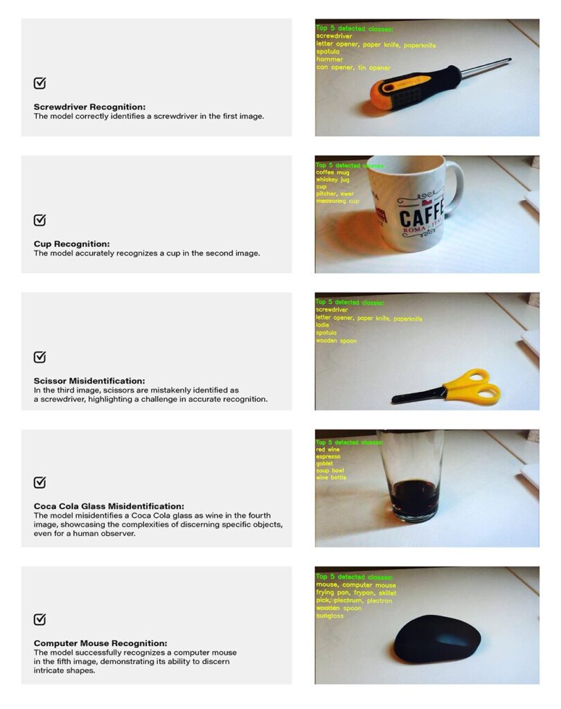
Challenges and Real-world Nuances: The test results underscore the challenges of accurate object recognition in less-than-ideal conditions. Factors such as image quality, lighting, and ambiguous object appearances contribute to the intricacy of the task. The third and fourth images, where scissors are misidentified as a screwdriver, and a Coca-Cola glass is misrecognized as wine, exemplify situations where even a human might face difficulty due to limited visual information-
Quality Considerations: The achieved results are noteworthy, considering the less-than-optimal quality of the test images. The chosen camera quality and lighting conditions intentionally mimic challenging real-world scenarios, making the model's performance commendable.
Conclusion: The real-world example of object recognition on Jacinto 7 highlights the capabilities and challenges associated with deploying AI models in practical scenarios. The successful identification of objects like a screwdriver, cup, and computer mouse demonstrates the model's efficacy. However, misidentifications in challenging scenarios emphasize the need for continuous refinement and adaptation, acknowledging the intricacies inherent in object recognition tasks, especially in dynamic and less-controlled environments.