Getting up to speed with Android Automotive OS development on Mac

Similar to how they did for the exploding smartphone market over ten years ago, customized infotainment operating systems and open-source software appear to be sweeping the car industry. The Android Automotive OS has been making headway in many market niches, starting with full-electric vehicles like Polestar a few years ago. It’s only a matter of time until the community and ecosystem mature enough to become a serious force for enabling mobile development on yet another front: the cars.
While Android Auto (a name easily confused with the topic I will be going over today) and Apple CarPlay have had a long-standing in the field, they came with several caveats and restrictions. Those largely pertain to the fact that many features-to-be would rely on low-level access to the hardware of the car itself. This proved to be difficult, with both solutions offering a limited set of human-machine interaction capabilities, such as a heads-up display (where available) and radio. With that in mind, the use case for providing apps for the actual OS running the car was clearly needed.
The community and documentation are still in their infancy and don’t yet provide a deep dive into Android Automotive OS. Moreover, the learning curve remains steep, but it’s definitely possible to piece together bits of information related to development and deployment. In this article, I attempt to do just that, all while emphasizing the MacOS side of things.
Prerequisites
As a general principle, Android development can either be done on a real device or a corresponding emulator. Given the sensitive nature of granting applications access to the actual car hardware, the app has to go the whole nine yards with Google Play Store eligibility. On top of that, it has to conform to one of several categories, e.g. a media app to be allowed in the AAOS system. The good news is that there’s a possibility for an app to mix and match categories.
Thus, vendors supporting the new ecosystem (as of now, among others, Volvo and Polestar) opted for creating a custom automotive device emulator that closely matches the specifications of the infotainment systems contained within their cars. Regrettably, Polestar and Volvo emulators contain proprietary code, are based on older Android releases, and do not yet support the ARM architecture, which is of special interest to developers working with ARM-based Macs.
While official AAOS emulators are available in Preview releases of Android Studio (from the Electric Eel version onwards), often the task at hand calls for customized hardware and parameters. In this case, a custom Android version would need to be built from source.
Building from source
Building from source code is a time-consuming enterprise that’s not officially supported outside 64-bit Linux platforms (regardless of the target architecture). With that in mind, choosing a dedicated AWS EC2 instance or a bare metal server for building the ARM versions of the emulator seems to be the best overall solution for Mac developers.
A requirement for unofficial builds on Mac devices seems to be having a disk partition with a case-sensitive file system and otherwise following some extra steps. I chose a dedicated build system because, in my opinion, it wasn't worth the trouble to set up an additional partition (for which I didn't really have the disk capacity).
The choice of the base Android release is largely dependent on the target device support, however, for ease of development, I would recommend choosing a recent one, e.g., 12.1 (aka 12L or Sv2). Mileage may vary in regards to actually supported versions, as vendors tend to use older and more stable releases.
After getting their hands on a development machine, one should prepare the build environment and follow instructions for building an AVD for Android Auto. The general workflow for building should include:
- downloading the source code – this may take up to an hour or two, even with decent connection and branch filtering,
- applying required modifications to the source, e.g., altering the default VHAL values or XML configuration,
- running the build – again, may take up to several hours; the more threads and memory available, the better,
- packing up the artifacts,
- downloading the AVD package.
Leaving out the usage specifics of the lunch and repo for now, let’s take a look at how we can make the default AAOS distribution fit our needs a little better.
Tailoring a device
VHAL (Vehicle Hardware Abstraction Layer) is an interface that defines the properties for OEMs to eventually implement. These properties may, for example, include telemetry data or perhaps some info that could be used to identify a particular vehicle.
In this example, we’re going to add a custom VIN entry to the VHAL. This will enable app developers to read VIN information from a supposed vehicle platform.
First off, let’s start with downloading the actual source code. As mentioned above, Android 12.1 (Sv2) is the release we’re going to go with. It supports version 32 of the API, which is more than enough to get us started.
In order to get sources, run the following command, having installed the source control tools :
<p>> repo init -u https://android.googlesource.com/platform/manifest -b android-12.1.0_r27 --partial-clone --clone-filter=blob:limit=10M</p>


<p>> repo sync -c -j16</p>
Partial clone capability and choice of a single branch make sure that the download takes as little time as possible.
After downloading the source, locate the DefaultConfig.h file and add the following entry to kVehicleProperties:
{.config =

     	{

             	.prop = toInt(VehicleProperty::INFO_VIN),

             	.access = VehiclePropertyAccess::READ,

             	.changeMode = VehiclePropertyChangeMode::STATIC,

     	},

 .initialValue = {.stringValue = "1GCARVIN123456789"}},
An overview of HAL properties can be found in the reference documentation .
Build
Having modified the default HAL implementation, we’re now free to run the build for an ARM target. Run the following instructions inside the AAOS source directory – using a screen is highly recommended if connecting through SSH:
screen

. build/envsetup.sh


lunch sdk_car_arm64-userdebug


m -j16      	                # build the requisite partitions


m emu_img_zip                   # pack emulator artifacts into a downloadable .zip
Note the sdk_car_arm64-userdebug target needed for emulation on ARM-powered Macs. A car_arm64-userdebug variant also exists. Make sure not to confuse the two – only the former has emulation capabilities! Try running lunch without parameters to see a full list of targets.
The -jXX parameter specifies the number of threads to use while building the Android. If the thread count is not provided, the build system will try and optimize the number of threads automatically. Patience is advised, as even with decent hardware resources, the compilation is bound to take a while.
The resulting emulator artifact should be available in the out/ directory under sdk-repo-linux-system-images.[suffix].zip to be downloaded via scp or your file transfer client of choice.
Running a custom emulator in Android Studio
Now that we have our bespoke emulator image built, there’s a little trick involved in making it available for local development without creating a whole distribution channel, as outlined in the manual.
First, locate the ~/Library/Android/sdk/system-images/android-32 folder and unzip your emulator archive there. The directory can be given an arbitrary name, but the overall structure should follow this layout:
~/Library/Android/sdk/system-images/android-32

|_ [your name]

   |_ arm64-v8a

E.g., ~/Library/Android/sdk/system-images/android-32/custom_aaos/arm64-v8a.
Second, download the example attached package.xml file and adjust the device name to fit your needs. A package.xml is added after downloading and unpacking the emulator sources from the Internet and needs to be recreated when unzipping locally. After restarting the Android Studio, Device Manager should have an option to use your brand new ARM image with an Automotive AVD of your choice.
After successfully running the emulator, a newly created VIN property should be visible in the Vhal Properties of Car Data. Nice one!
While reading VHAL property values is out of the scope of this article, it should be easy enough with a couple of Car library calls, and Google created an example app that does the very thing.
Downloading the above example (CarGearViewerKotlin) is highly recommended – if you’re able to build and run the app on the emulator, you’re all set!
Facilitating AAOS development on M1
One of the problems I stumbled upon during the development environment setup was that the Car library was not being detected by Android Studio, while the app still builds normally from CLI. This appears to be a known issue, with no official patch yet released (as of October 2022). However, a simple workaround to include a .jar of the Android Automotive library appears to work.
In case of running into any problems, import the library from ~/Library/Android/sdk/platforms/android-32/optional/android.car.jar by copying it into libs/ directory in the project root and add the following directive to your main build.gradle file, if not present:
dependencies {

	implementation fileTree(include: ['*.jar'], dir: 'libs')

	...

}
Once the project is re-imported into the IDE, Android Studio should be able to pick up the Android Car library for import and autocomplete suggestions.
The Real Deal
Emulators are sufficient for testing purposes, but what about real devices, such as branded infotainment centers? As mentioned before, at least two major vendors (Volvo and Polestar) offer the integrated Android Automotive experience out-of-the-box in their vehicles. System images and implementation details, however, are proprietary and require enrollment into their respective developer partnership programs. Polestar offers a free AV D that emulates Polestar 2 behavior, along with the screen size, frame and hardware controls – alas, currently only available for x86-64 platforms.
One of the alternatives worth considering is the installation of Android Automotive on a real device – be it a tablet or even a Raspberry Pi platform . Some modules will still require virtualization, but switching to a physical device could be a major step in the direction of better hardware compatibility.
All the above concerns raise the question – how to get the app to work on a real AAOS inside a car? I haven’t found a conclusive answer to that question, at least one that won’t involve third parties holding the actual documentation resources for their devices. It makes sense that some doors will stay closed to the general programming audience due to the security implications of creating apps for cars. No one, after all, would want their vehicle to be taken control of by a rogue party, would they?
Final thoughts
Programming for Android Automotive is still an adventurous endeavor. Even though the system has been around since 2017 (with APIs open to public in mid-2019), official documentation can still feel somewhat inaccessible to newcomers, and the developer community is still in its budding phase. This requires one to piece together various bits of official guides and general Stack Overflow knowledge.
Bottom line: AAOS is still behind the degree of engagement that the regular Android operating system has been enjoying so far. The future is looking bright, however, with vendors such as GM, Honda, BMW, and Ford eager to jump on the automotive development bandwagon in years to come. If that’s the case, the ecosystem will inevitably expand – and so will the community and the support it provides.

Grape Up guides enterprises on their data-driven transformation journey
Ready to ship? Let's talk.
Check related articles
Read our blog and stay informed about the industry's latest trends and solutions.
Android Automotive OS 14 is out – build your own emulator from scratch!
Android Automotive OS 14 has arrived, and it marks a significant evolution in the way users interact with their vehicle's system. This version brings enhanced user experience, improved Android API, and better OS-level security (as well as non-automotive Android 14). In this short article, we'll walk you through a tutorial on creating your own emulator from scratch, but first, here are some of the standout features and improvements introduced in Android Automotive OS 14 !
Android Automotive 14 noteworthy new features
- Enhanced UI: Now with an optional, improved home screen adaptation to the portrait mode for better vehicle compatibility.
- Multi-User Upgrades: Support parallel sessions with custom sound zones and multiple displays.
- Remote Access: Enables system wake-up, executes a task and then shutdown via external requests.
- Extended VHAL: More ADAS and non-ADAS properties included to represent activation status and the system state.
- App Quick Actions: A feature that allows applications to showcase quick actions.
- Infotainment Reference Design: The starting point for developers to create apps for Android Automotive OS.
- New Boot Animation: Well, as usual 😊
To learn about all new features provided in Android Automotive 14, follow this link: https://source.android.com/docs/automotive/start/releases/u_udc_release?hl=en
Steps to building an emulator
The best operating system for building an emulator in AAOs is Ubuntu 18.04 or higher. If you use a different operating system, you must follow some extra steps. For instance, you may need to install a repo from https://gerrit.googlesource.com/git-repo instead of using a package manager.
1) You need first to install the required dependencies
sudo apt install git-core gnupg flex bison build-essential zip curl zlib1g-dev libc6-dev-i386 libncurses5 x11proto-core-dev libx11-dev lib32z1-dev libgl1-mesa-dev libxml2-utils xsltproc unzip fontconfig repo
2) Then, configure Git, set your name and email address
git config --global user.name "Your name"
git config --global user.email your@email
3) After configuring Git, you can download source code from a Git repository
repo init -u https://android.googlesource.com/platform/manifest -b android-14.0.0_r54 --partial-clone --clone-filter=blob:limit=10M && repo sync
You can skip ‐‐ partial-clone and ‐‐ clone-filter. However, this will result in longer download times. It’s recommended to check for the latest android-14.0.0_rXX tag before downloading, which can be found on this page: https://android.googlesource.com/platform/manifest/+refs .
Keep in mind that downloading takes a lot of time because the sources take about 150GB even with partial clone and clone-filter enabled.
4) In the next step, set up environment variables using the script provided
. build/envsetup.sh
This method replaces your JAVA_HOME and modifies PATH, so be aware that your console may act differently now.
5) Select the system to build
lunch sdk_car_portrait_x86_64-eng
You can create a landscape build by removing "portrait". Also, change x86_64 to arm64 if you want to run the system on Mac. For more details on building on Mac, check out this article .
6) Create the system and the emulator image
m && m emu_img_zip
The first command will take hours to complete. Take a break: go running, biking, hiking, or whatever drives you. You can modify threat pool usage by the build system with -j parameter, like m -j 16 – the default one is the CPU count of your machine.
7) Copy the emulator image to Android Studio emulator directory
mkdir -p /mnt/c/Users/<user>/AppData/Local/Android/Sdk/system-images/android-34/custom_aaos_14/ && unzip -o out/target/product/emulator_x86_64/sdk-repo-Linux-system-images-eng.dape.zip -d /mnt/c/Users/<user>/AppData/Local/Android/Sdk/system-images/android-34/custom_aaos_14/
I assume you work on a Windows machine with WSL. Please adapt the above commands with your Android/SDK directory if you are working on native Linux.
Create a package.xml file in /mnt/c/Users/<user>/AppData/Local/Android/Sdk/system-images/android-34/custom_aaos_14/x86_64 directory with the this content . The file provided bases on existing package.xml files in other emulator images.
Adjust “tag”, “vendor”, and “display name” in the upper file if needed. Make sure to match <localPackage obsolete="false" path="system-images;android-34;custom_aaos_14;x86_64"> with the path you’d placed the emulator image.
8) Now it’s time to create a new emulator in Android Studio
Open "Device Manager" and select "Create Virtual Device". In the left-hand menu, choose "Automotive" and add a new hardware profile using the button in the lower-left corner of the panel.
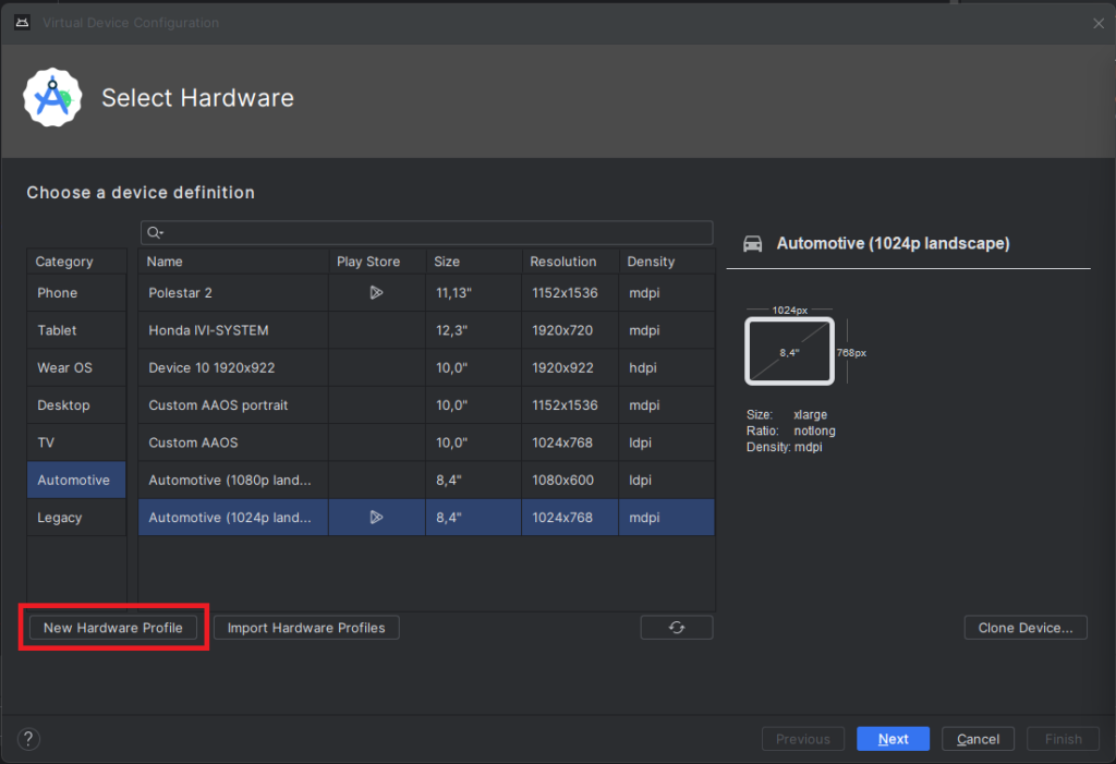
Select “Android Automotive” as a device type. Choose the correct resolution for your build. For example, I selected a resolution of 1152x1536 for a 10-inch device to create a portrait build. Next, allocate at least 1536 MB of RAM to your device. Then, choose only one supported device state - "Portrait" or "Landscape" - according to your build. Finally, disable any unnecessary sensors and skin for AAOS compatibility.
9) Accept and select your new hardware profile. Then, move on to the next step
10) Pick your emulator image (you can find it using the tag and vendor configured in package.xml)
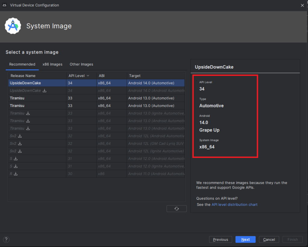
11) On the final screen, enter a name and complete the configuration process
12) To start the emulator, go to the "Device Manager" and launch it from there
13) You’re all set! Enjoy!
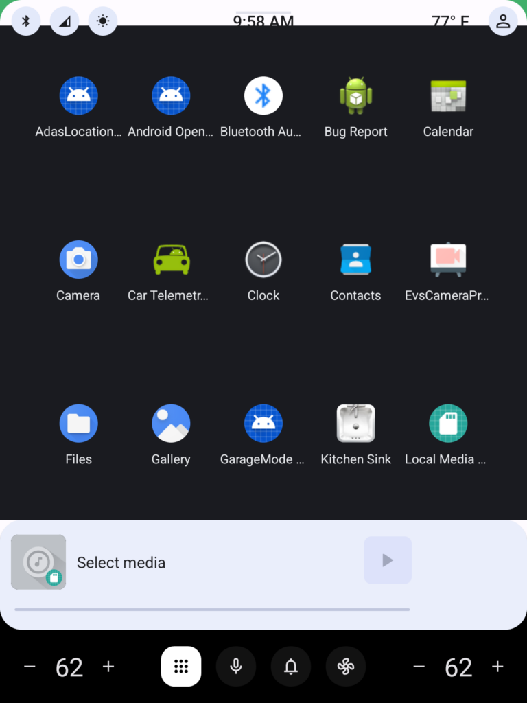
Get started on creating your very own Android Automotive OS 14 emulator by following the steps outlined in this article. Explore the possibilities of car technology and discover what the future has in store. You can find a AAOS “Hello World” example in our article How to Build Your First App for Android Automotive OS . Start building, try out the various features, and have fun with your new setup!
Build and run Android Automotive OS on Raspberry Pi 4B
Have you ever wanted to build your own Android? It’s easy according to the official manual, but it’s getting harder on a Windows (or Mac) machine, or if you’d like to run it on physical hardware. Still too easy? Let’s build Android Automotive OS – the same source code, but another layer of complexity. In this manual, we’ll cover all steps needed to build and run Android Automotive OS 11 AOSP on Raspberry Pi 4B using Windows. The solution is not perfect, however. The most principal issue is a lack of Google Services because the entire AAOS is on an open-source project and Google doesn’t provide its services this way. Nevertheless, let’s build the open-source version first, and then we can try to face incoming issues.
TL;DR: If you don't want to configure and build the system step-by-step, follow the simplified instruction at https://github.com/grapeup/aaos_11_local_manifest
Prerequisites
Hardware
If you want to run the system on a physical device, you need one. I use the Raspberry Pi 4 model B with 8GB of RAM ( https://www.raspberrypi.com/products/raspberry-pi-4-model-b/ ). By the way, if you want to build and run an emulator from the source, it’s also possible, but there is a small limitation – packaging the emulator to a zip file, moving it to another computer, or even running it under Android Studio was introduced in Android 12.
To power your Raspberry, you need a power adapter (USB C, min. 5V 3A). I use the Raspberry-official 5.1V 3A model. You can also power the Raspberry computer from your desktop/laptop’s USB port, especially if you’re going to debug it via a serial connection. Check the “If it doesn’t work” section below for the required hardware.
Another piece of hardware needed is an SD card. In theory, 4GB is all you need, however, I recommend buying a larger card to have some extra space for your applications on Android . I use 32GB and 64GB cards. You’ll also need a built-in or external card reader. I use the latter.
The next step is a screen. It’s optional but fancy. You can connect your mouse and optionally keyboard to your Raspberry Pi via USB and connect any display you have via micro-HDMI but using a touch screen is much more intuitive. I use a Waveshare 10-inch screen dedicated to Raspberry ( https://www.waveshare.com/wiki/10.1inch_HDMI_LCD_(B)_(with_case ). The screen box has a place to screw the Raspberry too, so you don’t need any extra case. You can also buy it with a power adapter and a display cable.
If you don’t buy a bundle, make sure you have all necessary accessories: micro-HDMI – HDMI cable to connect a screen (Waveshare or any other), USB A – USB mini A cable to connect a touch sensor of the screen, USB mini A 5V 3A adapter to power the screen.
Of course, you need a computer. In this manual, we use a Windows machine with at least 512GB of storage (the Android source is huge) and 16GB of RAM.
Software
You can probably build everything in pure Windows, but the recommended method is to use WSL. I assume you already have it installed, so just make sure you have the newest WSL2 version. If you have never used WSL before, see the full manual here https://learn.microsoft.com/en-us/windows/wsl/install .
WSL adjustments
The standard WSL installation uses a too-small virtual drive and limited RAM, so you need to adjust it.
Let’s start with the disk. Make sure the WSL is shut down by running ‘wsl –shutdown’ in the command prompt. Open Windows Command Prompt with admin privileges and enter ‘diskpart ’. Then run ‘select vdisk file=”<path to WSL drive file>”’. For me, the path is “C:\Users\<user>\AppData\Local\Packages\CanonicalGroupLimited.Ubuntu_<WSL_instance_id>\LocalState\ext4.vhdx ”. Now you can expand it with the command ‘expand vdisk maximum=512000’. Around 300GB is enough for Android 11, but if you want to play with multiple branches of Android at the same time, you need more space. Now you can close the diskpart with the ‘exit’ command. Next, open the WSL and run ‘sudo resize2fs /dev/sdb 512000M’. I assume you have only a single drive attached to the WSL and it’s visible in the Linux subsystem as /dev/sdb. You can check it with the commands ‘sudo mount -t devtmpfs none /dev || mount | grep ext4’.
Now, let’s adjust the memory. Stop the WSL again. Open your home directory in Windows and open .wslconfig file. Create it if this file doesn’t exist yet. In the file, you need to create a [wsl2] section and memory configuration. The complete file should look like this:
[wsl2]
memory=16GB
As you can see, I’ve attached 16GB to the virtual machine. It’s assigned dynamically, according to needs, but you must be aware that the virtual machine can take all of it, so if you allow it to eat your entire RAM, it can force your Windows to use a hard disk to survive (which will slow everything down significantly).
Disclaimer:
Building Android on 8 cores, 16GB RAM machine takes around 4 hours. If you want to do it faster or you don’t have a computer powerful enough at your home or office, you can consider building in the cloud. Simple AWS EC2 with 32 cores and 64GB of memory does the job in one hour (to download and build) and costs just a few bucks.
Let's get ready to rumble!!!
..or at least to building.
More prerequisites
We need some software but not much. Just install the following packages. This set of libraries allows you to build Android Automotive OS versions 11 to 13.
sudo apt update && sudo apt install gcc-aarch64-linux-gnu libssl-dev bc python3-setuptools repo python-is-python3 libncurses5 zip unzip make gcc flex bison -y
Source code downloading
Let’s create a home directory for our android and download sources.
mkdir android-11.0.0_r48 && cd android-11.0.0_r48
repo init -u https://android.googlesource.com/platform/manifest -b android-11.0.0_r48 --partial-clone --clone-filter=blob:limit=10M
git clone https://github.com/android-rpi/local_manifests .repo/local_manifests -b arpi-11
repo sync
“repo init” will ask you for some personal data. It’s collected by Google. To learn more about optimizations here, check this manual: https://docs.gitlab.com/ee/topics/git/partial_clone.html . ‘git clone’ adds a custom code from Android RPI project ( https://groups.google.com/g/android-rpi ) with drivers for your Raspberry Pi. The project is great and it’s all you need if you want to run Android TV. To run Android Automotive OS, we’ll need to adjust it slightly (see “Adjustments” section below). ‘repo sync’ will take some time because you need to download around 200GB of code. If you have a powerful machine with a great Internet connection, you can use more threads with ‘-j X’ parameter added to the command. The default thread count is 4. If you have already synchronized your source code without android-rpi local manifest, you need to add --force-sync to the ’repo-sync’ command.
Adjustments
All changes from this section can download as a patch file attached to this article. See the “Path file” section below.
Android-rpi provides Android TV for Raspberry Pi. We need to remove the TV-related configuration and add the Automotive OS one.
Let’s start with removing unnecessary files. You can safely remove the following files and directories:
- device/arpi/rpi4/overlay/frameworks/base/core/res/res/anim
- device/arpi/rpi4/overlay/frameworks/base/core/res/res/values-television
- device/arpi/rpi4/overlay/frameworks/base/core/res/res/values/dimens.xml
- device/arpi/rpi4/overlay/frameworks/base/core/res/res/values/styles.xml
- device/arpi/rpi4/overlay/frameworks/base/packages
To remove the user notice screen not needed in Automotive OS, create a new file device/arpi/rpi4/overlay/packages/services/Car/service/res/values/config.xml with the following content:
<?xml version="1.0" encoding="utf-8"?>
<resources xmlns:xliff="urn:oasis:names:tc:xliff:document:1.2">
<string name="config_userNoticeUiService" translatable="false"></string>
</resources>
To replace the basic TV overlay config with the Automotive overlay config, adjust the configuration in device/arpi/rpi4/overlay/frameworks/base/core/res/res/values/config.xml.
Remove:
- <integer name="config_defaultUiModeType">4</integer> <!--disable forced UI_MODE_TYPE_TELEVISION, as there is only MODE_TYPE_CAR available now-->
- <integer name="config_longPressOnHomeBehavior">0</integer> <!--disable home button long press action-->
- <bool name="config_hasPermanentDpad">true</bool> <!--disable D-pad-->
- <string name="config_appsAuthorizedForSharedAccounts">;com.android.tv.settings;</string> <!--remove unnecessary access for a shared account as there is nothing in com.android.tv.* now-->
… and add:
- <bool name="config_showNavigationBar">true</bool> <!--enable software navigation bar, as there is no hardwave one-->
- <bool name="config_enableMultiUserUI">true</bool> <!--enable multi-user, as AAOS uses background processes called in another sessions -->
- <integer name="config_multiuserMaximumUsers">8</integer> <!--set maximum user count, required by the previous one-->
Now let’s rename the android-rpi original /device/arpi/rpi4/rpi4.mk to /device/arpi/rpi4/android_rpi4.mk. We need to adjust the file a little bit.
Remove the following variables definitions. Some of them you will re-create in another file, while some of them are not needed.
- PRODUCT_NAME
- PRODUCT_DEVICE
- PRODUCT_BRAND
- PRODUCT_MANUFACTURER
- PRODUCT_MODEL
- USE_OEM_TV_APP
- DEVICE_PACKAGE_OVERLAYS
- PRODUCT_AAPT_PRED_CONFIG
- PRODUCT_CHARACTERISTICS
Remove the following invocations. We’re going to call necessary external files in another mk file.
- $(call inherit-product, device/google/atv/products/atv_base.mk)
- $(call inherit-product, $(SRC_TARGET_DIR)/product/core_64_bit_only.mk)
- $(call inherit-product, $(SRC_TARGET_DIR)/product/languages_full.mk)
- include frameworks/native/build/tablet-10in-xhdpi-2048-dalvik-heap.mk
In PRODUCT_PROPERTY_OVERRIDES remove debug.drm.mode.force=1280x720 and add the following properties. This way you remove the TV launcher configuration and override the default automotive launcher configuration.
- dalvik.vm.dex2oat64.enabled=true
- keyguard.no_require_sim=true
- ro.logd.size=1m
Now you need to completely remove the android-rpi TV launcher and add RenderScript support for Automotive OS. In PRODUCT_PACKAGES remove:
- DeskClock
- RpLauncher
… and add:
- librs_jni
Create a new rpi4.mk4 with the following content:
PRODUCT_PACKAGE_OVERLAYS += device/generic/car/common/overlay
$(call inherit-product, $(SRC_TARGET_DIR)/product/core_64_bit.mk)
$(call inherit-product, device/arpi/rpi4/android_rpi4.mk)
$(call inherit-product, $(SRC_TARGET_DIR)/product/full_base.mk)
$(call inherit-product, device/generic/car/common/car.mk)
PRODUCT_SYSTEM_DEFAULT_PROPERTIES += \
android.car.number_pre_created_users=1 \
android.car.number_pre_created_guests=1 \
android.car.user_hal_enabled=true
DEVICE_PACKAGE_OVERLAYS += device/arpi/rpi4/overlay device/generic/car/car_x86_64/overlay
PRODUCT_NAME := rpi4
PRODUCT_DEVICE := rpi4
PRODUCT_BRAND := arpi
PRODUCT_MODEL := Raspberry Pi 4
PRODUCT_MANUFACTURER := GrapeUp and ARPi
Due to the license, remember to add yourself to the PRODUCT_MANUFACTURER field.
Now you have two mk files – android-rpi.mk is borrowed from android-rpi project and adjusted, and rpi.mk contains all changes for Automotive OS. You can meld these two together or split them into more files if you’d like, but keep in mind that the order of invocations does matter (not always, but still).
As Android Automotive OS is bigger than Android TV, we need to increase the system partition size to fit the new image. In device/arpi/rpi4/BoardConfig.mk increase BOARD_SYSTEMIMAGE_PARTITION_SIZE to 2147483648, which means 2GB.
You need to apply all changes described in https://github.com/android-rpi/device_arpi_rpi4/wiki/arpi-11-:-framework-patch too. Those changes are also included in the patch file attached .
If you use the 8GB version of Raspberry Pi, you need to replace device/arpi/rpi4/boot/fixup4.dat and device/arpi/rpi4/boot/start4.elf files. You can find the correct files in the patch file attached or you may use the official source: https://github.com/raspberrypi/firmware/tree/master/boot . It’s probably not needed for 4GB version of Raspberry, but I don’t have such a device for verification.
Path file
If you prefer to apply all changes described above as a single file, go to your sources directory and run ‘git apply --no-index <path_to_patch_file> ’. There is also a boot animation replaced in the patch file . If you want to create one of your own, follow the official manual here: https://android.googlesource.com/platform/frameworks/base/+/master/cmds/bootanimation/FORMAT.md .
Now we can build!
That’s the easy part. Just run a few commands from below. Firstly, we need to build a custom kernel for Android. ‘merge_config.sh’ script just configures all variables required. The first ‘make’ command builds the real kernel image (which can take a few minutes). Next, build a device tree configuration.
cd kernel/arpi
ARCH=arm64 scripts/kconfig/merge_config.sh arch/arm64/configs/bcm2711_defconfig kernel/configs/android-base.config kernel/configs/android-recommended.config
ARCH=arm64 CROSS_COMPILE=aarch64-linux-gnu- make Image.gz
ARCH=arm64 CROSS_COMPILE=aarch64-linux-gnu- DTC_FLAGS="-@" make broadcom/bcm2711-rpi-4-b.dtb
ARCH=arm64 CROSS_COMPILE=aarch64-linux-gnu- DTC_FLAGS="-@" make overlays/vc4-kms-v3d-pi4.dtbo
cd ../..
The next part is to build the entire system. “envsetup.sh” script sets up variables and adds custom commands to your terminal. Then you can pick the correct pair of Android versions and devices with “lunch”. You can run it without parameters to see (almost) all possible configurations. In this step, you can decide to build a system for dedicated hardware (eg. Dragonboard) and switch between phone/tablet/TV/wearable/automotive versions of Android. The last line is a real building. We can’t run just “make” or “m”, as documented in the official manual because we need to create three specific images to write them on an SD card and run them on Raspberry Pi. Replace “X” in ‘-j X’ with the number of threads you want to use. The default value is the number of logical processors on your computer.
source build/envsetup.sh
lunch rpi4-eng
make -j X ramdisk systemimage vendorimage
I hope you have a delightful book next to you because the last building takes a few hours depending on your hardware. Good news! If you need to adapt something and build again, in most cases you just need the three last lines (or even just the very last one) – to source the environment setup, to pick the lunch configuration, and to make ramdisk, system, and vendor images. And it takes hours for the first time only.
Creating an SD card
This step seems to be easy, but it isn’t. WSL doesn’t contain drivers for the USB card reader. You can use usbip to forward a device from Windows to the subsystem, but it doesn’t work well with external storage without partitions. The solution is a VirtualBox with Ubuntu installed. Just create a virtual machine, install Ubuntu, and install Guest Additions. Then you can connect the card reader and pass it to the virtual machine. If you’re a minimalist, you can use Ubuntu Server or any other Linux distribution you like. Be aware that using a card reader built into your computer may be challenging depending on drivers and the hardware connection type (USB-like, or PCI-e).
Now, you need to create a partition schema on the SD card. I assume the card is loaded to the system as /dev/sdb. Check your configuration before continuing to avoid formatting your main drive or another disaster. Let’s erase the current partition table and create a new one.
sudo umount /dev/sdb*
sudo wipefs -a /dev/sdb
sudo fdisk /dev/sdb
Now let’s create partitions. First, you need a 128MB active partition of the W95 FAT32 (LBA) type, second a 2GB Linux partition, third a 128MB Linux partition, and the rest of the card for user data (also Linux partition). Here’s how to navigate through fdisk menu to configure all partitions.
Welcome to fdisk (util-linux 2.37.2).
Changes will remain in memory only, until you decide to write them.
Be careful before using the write command.
Device does not contain a recognized partition table.
Created a new DOS disklabel with disk identifier 0x179fb9bc.
Command (m for help): n
Partition type
p primary (0 primary, 0 extended, 4 free)
e extended (container for logical partitions)
Select (default p):
Using default response p.
Partition number (1-4, default 1):
First sector (2048-61022207, default 2048):
Last sector, +/-sectors or +/-size{K,M,G,T,P} (2048-61022207, default 61022207): +128M
Created a new partition 1 of type 'Linux' and of size 128 MiB.
Command (m for help): a
Selected partition 1
The bootable flag on partition 1 is enabled now.
Command (m for help): t
Selected partition 1
Hex code or alias (type L to list all): 0c
Changed type of partition 'Linux' to 'W95 FAT32 (LBA)'.
Command (m for help): n
Partition type
p primary (1 primary, 0 extended, 3 free)
e extended (container for logical partitions)
Select (default p):
Using default response p.
Partition number (2-4, default 2):
First sector (264192-61022207, default 264192):
Last sector, +/-sectors or +/-size{K,M,G,T,P} (264192-61022207, default 61022207): +2G
Created a new partition 2 of type 'Linux' and of size 2 GiB.
Command (m for help): n
Partition type
p primary (2 primary, 0 extended, 2 free)
e extended (container for logical partitions)
Select (default p):
Using default response p.
Partition number (3,4, default 3):
First sector (4458496-61022207, default 4458496):
Last sector, +/-sectors or +/-size{K,M,G,T,P} (4458496-61022207, default 61022207): +128M
Created a new partition 3 of type 'Linux' and of size 128 MiB.
Command (m for help): n
Partition type
p primary (3 primary, 0 extended, 1 free)
e extended (container for logical partitions)
Select (default e): p
Selected partition 4
First sector (4720640-61022207, default 4720640):
Last sector, +/-sectors or +/-size{K,M,G,T,P} (4720640-61022207, default 61022207):
Created a new partition 4 of type 'Linux' and of size 26,8 GiB.
Command (m for help): w
The partition table has been altered.
Calling ioctl() to re-read partition table.
Syncing disks.
Be careful with the last partition – fdisk proposes creating an extended one by default, which is not needed in our use case.
If you don’t do it for the first time on the same card, you may see a warning that some partition already contains a file system signature. You can safely agree to remove it.
Partition #4 contains a ext4 signature.
Do you want to remove the signature? [Y]es/[N]o: Y
The signature will be removed by a write command.
Now, let’s supply file systems for the first and the last partitions.
sudo mkdosfs -F 32 /dev/sdb1
sudo mkfs.ext4 -L userdata /dev/sdb4
We won’t write anything to the last one, as it’s for user data only and will be filled by Android during the first boot. But we need to write some files for the first one. Let’s create a temporary mount directory under /mnt/p1 (like “partition 1”), mount it, and copy the necessary files from the Android built in the earlier section. It’s strange, but we’re going to copy files from one virtual machine (WSL) to another (VirtualBox). You can simply mount a wsl drive as a shared folder in VirtualBox. If you don’t see a WSL drive in your Windows Explorer, you can map it as a network drive using “\\wsl$\Ubuntu” path
sudo mkdir /mnt/p1
sudo mount /dev/sdb1 /mnt/p1
sudo mkdir /mnt/p1/overlays
cd <PATH_TO_YOUR_ANDROID_SOURCES_IN_WSL>
sudo cp device/arpi/rpi4/boot/* /mnt/p1
sudo cp kernel/arpi/arch/arm64/boot/Image.gz /mnt/p1
sudo cp kernel/arpi/arch/arm64/boot/dts/broadcom/bcm2711-rpi-4-b.dtb /mnt/p1
sudo cp kernel/arpi/arch/arm/boot/dts/overlays/vc4-kms-v3d-pi4.dtbo /mnt/p1/overlays/
sudo cp out/target/product/rpi4/ramdisk.img /mnt/p1
sudo umount /mnt/p1
sudo rm -rf /mnt/p1
If you’re looking at the official android-rpi project manual, there is a different path for vc4-kms-v3d-pi4.dtbo file. That’s OK – they use a symbolic link we are unable to use in this filesystem.
Sometimes, you can see an error message when creating an “overlays” directory. It happens from time to time, because “mount” returns to the console before really mounting the drive. In such a case, just call “mkdir” again. Be aware of that, especially if you’re going to copy-paste the entire listing from above.
Now, let’s copy the two remaining partitions. If you’re struggling with dd command (it may hang), you can try to copy big *.img files from WSL to VirtualBox first.
cd <PATH_TO_YOUR_ANDROID_SOURCES_IN_WSL>/out/target/product/rpi4/
sudo dd if=system.img of=/dev/sdb2 bs=1M status=progress
sudo dd if=vendor.img of=/dev/sdb3 bs=1M status=progress
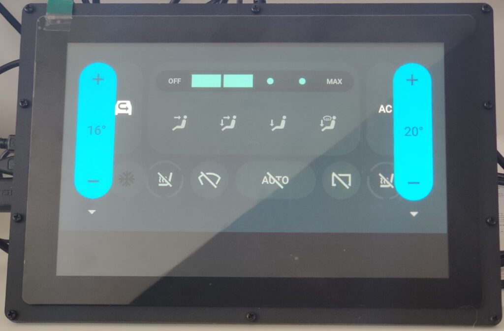
Congratulations!
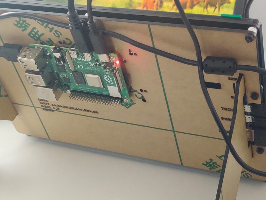
You’re done. You’ve downloaded, prepared, built, and saved your own Android Automotive OS. Now you can put the SD card into Raspberry, and connect all cables (make sure you connect the Raspberry power cable at the end). There is no “power” button, and it doesn’t matter which micro-HDMI or USB port of Raspberry you use. It’s now time to enjoy your own Android Automotive OS!
If it doesn’t work
The world is not perfect and sometimes something goes terribly wrong. If you see the boot animation for a long time, or if your device crashes in a loop a few seconds after boot, you can try to debug it.
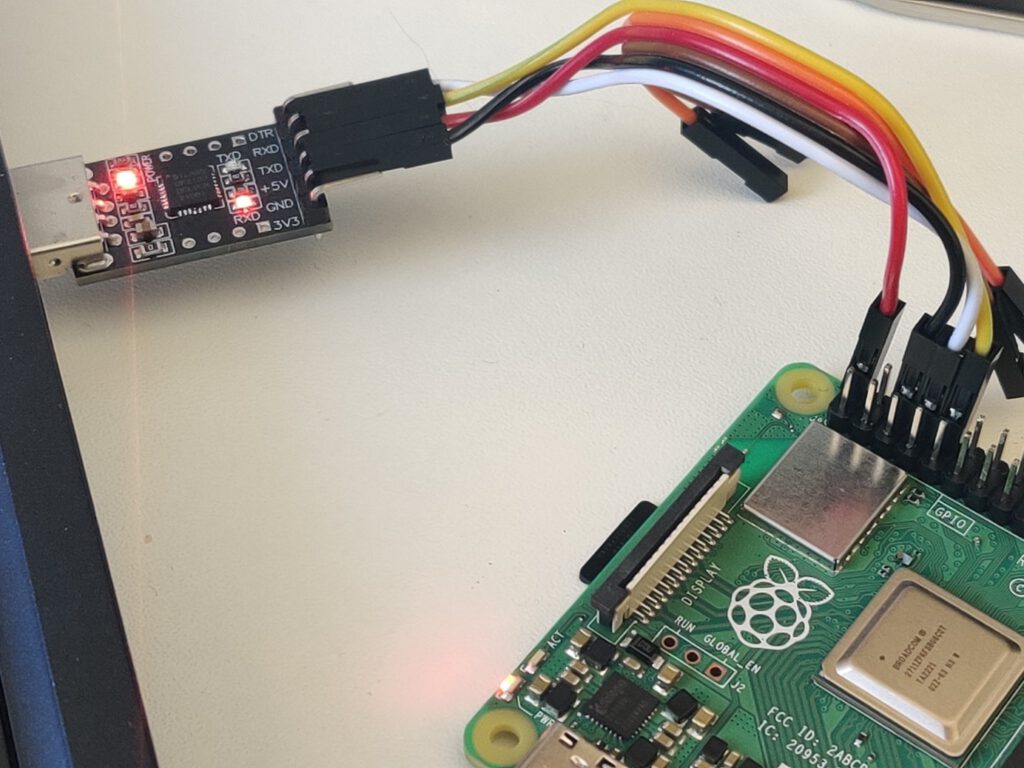
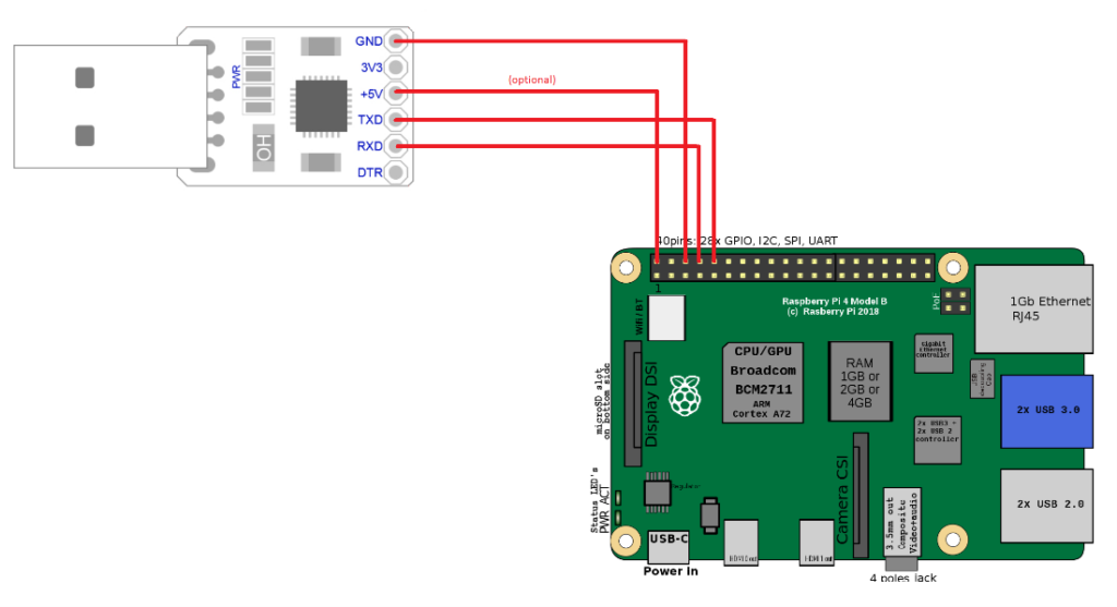
You need a USB-TTL bridge (like this one https://www.sunrom.com/p/cp2102-usb-ttl-uart-module ) to connect the correct pins from the Raspberry to the USB. You need to connect pin 6 (ground) to the GND pin in the bridge, pin 8 (RXD) to the RXD pin of the bridge and pin 10 (TXD) to the TXD pin of the bridge. If you want to power the Raspberry via the bridge, you need to also connect pin 2 to +5V pin of the bridge. It is not recommended, because of the lower voltage, so your system might be unstable. If you don’t have a power adapter, you can simply connect a USB cable between your computer port and the USB C port of the Raspberry. Warning! You can’t connect both a +5V connector here and a USB C power port of the Raspberry or you’ll burn the Raspberry board.
See the schema for the connection reference.
Depending on your bridge model, you may need an additional driver. I use this one: https://www.silabs.com/developers/usb-to-uart-bridge-vcp-drivers?tab=downloads .
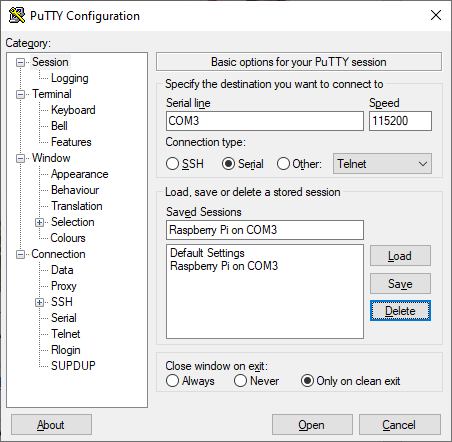
When you connect the +5V pin or USB-C power adapter ( again, never both at the same time! ), the Raspberry starts. Now you can open Putty and connect to your Android. Pick Serial and type COMX in the serial line definition. X is the number of your COM port. You can check it in your device manager – look for “USB to UART bridge (COM4)” or the like. The correct connection speed is 115200.
Open the connection to access the Android shell. By default, Android spawns all logs to the standard output, so you should see a lot of them right away. Anyway, it’s dual-side communication and you have full terminal access to your Android if you need to check/modify any file or call any command. Just strike enter to see the command prompt. You can even call ‘su’ to gain superuser access on your Android running on Raspberry.
Connecting via adb
If you want to use Android Debug Bridge to connect to your device, using a USB bridge is not enough. When running ‘adb devices’ on your computer, the Android Automotive OS running on Raspberry is not recognized. You can use a putty connection to turn on a TCP debug bridge instead.
Make sure you’ve connected Android and your computer to the same network. Open putty and connect to the running Android console. Log as root and enable ADB via TCP. Then check your IP address.
su
setprop service.adb.tcp.port 5555
stop adbd
start adbd
ifconfig wlan0
Now, using your Windows command line, go to the Android SDK platform-tools directory and connect to your device. As you can see, the IP address of mine Raspnberry is 192.168.50.47.
cd %userprofile%\AppData\Local\Android\Sdk\platform-tools
adb connect 192.168.50.47:5555
If you want to use ADB in WSL, you can link the Windows program in WSL using the following command.
sudo ln -s /mnt/c/Users/<your_username>/AppData/Local/Android/Sdk/platform-tools/adb.exe /usr/bin/adb
You can now use ADB to use logcat without putty or to install applications without manually transferring APK files to the SD card. Fun fact – if you use a USB bridge and USB power supply, you have two physical connections between your computer and the Android-running one, however, you still need to use ADB over WiFi to use the debug bridge.
Summary: Android Automotive OS on Raspberry Pi 4B
That’s all. Android Automotive OS 11 is running. You can install the apps you need, take them to your car, or do whatever you’d like with them. Using hardware instead of an emulator allows you to manually manage partitions (e.g. for the OTA update ) and connect external devices like a real GPS receiver or accelerometer. The bare metal hardware overperforms the emulator too. And most importantly – you can easily take it to your car, receive power from an in-car USB port, connect it to an ODB-II port and run real-life tests without a laptop.
Is your project ready? Great, now you can try doing the same with AAOS 13 .
Interested in our services?
Reach out for tailored solutions and expert guidance.